Evaluation Kit Manual
R16UZ0019EU0100 Rev.1.00 Page 1
Sep 23, 2021 © 2021 Renesas Electronics
Overview
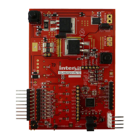
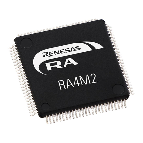
The RTKA489204DK0000BU is an evaluation kit that
facilitates testing of the RAA489204 Li-ion battery
pack analog front-end ICs. The RAA489204 monitors
cell voltage and temperature, and provides 14-bit
digital values, cell balance control, and significant
fault detection. The RAA489204 also contains daisy
chain hardware to provide robust board-to-board
communication.
The evaluation kit operates as a stand-alone monitor
or, combined with additional boards, creates a daisy
chained application. One board operating alone
allows testing of up to 14-cell series-connected Li-ion
battery packs by using a standard USB interface to a
PC. Up to 30 boards cascade (with daisy chain
communication from board-to-board) to test systems
with up to 420 cells.
Specifications
This board is configured and optimized for the
following operating conditions:
▪V
BAT = 12V to 65V
▪ Cell voltage -5V to +5V (Note: No cell voltage can
go below pack ground or above 65V.)
▪ External inputs ExT1 to ExT4 = 0V to 2.5V
(external temperature measurement thermistors on
board)
▪ Two GPIO ports to monitor temperature (default) or
general-purpose input or output.
Board Contents
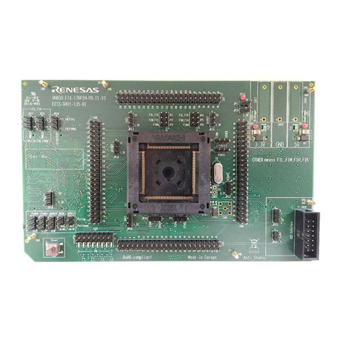
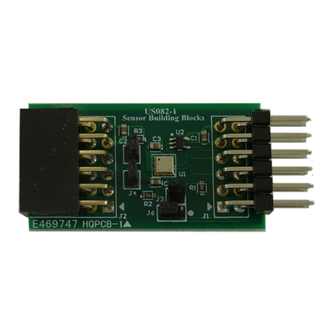
The RTKA489204DK0000BU evaluation kit contains:
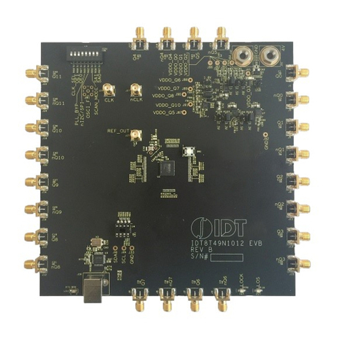
▪ RTKA489204DE0000BU RevB evaluation board
▪ MCB_PS4_Z multi-cell power supply test board
▪ RTKA489204MICROZ communications board
▪ USB cable that connects PC to evaluation board
▪ One twisted pair daisy chain cable
▪ One RJ45 daisy chain cable
Features
▪ Supports both stand-alone and daisy chained
configurations
▪ Daisy chain capacitively coupled (direct board-to-
board or cable connected) or transformer coupled
cable connected (capacitor or transformer selected
by jumper)
▪ External cell balance operation
▪ Cell voltages monitored after balance resistor to
meet safety fault detection goals.
▪ GUI provided export option for generation of
detailed register, voltage, and/or SPI
communications log files
▪ USB microcontroller dongle runs HID firmware for
enumeration and communications with Windows
platforms
▪ Evaluation kit includes a resistor divider power
supply board for cell voltage generation
Board Requirements
The following instruments are required to perform
testing:
▪ 63V/1A adjustable power supply
▪ Wires to connect power supply to MCB_PS4_Z
board
▪ Precision multimeter
▪ Windows computer with USB port
RTKA489204DK0000BU
