Renishaw TP200 User manual

#renishaw
TP200 product care guide
www.renishaw.com/TP200

2TP200 product care guide
© 2008 - 2023 Renishaw plc. All rights reserved.
This document may not be copied or reproduced in whole or
in part, or transferred to any other media or language by any
means, without the prior written permission of Renishaw.
Disclaimer
WHILE CONSIDERABLE EFFORT WAS MADE TO VERIFY
THE ACCURACY OF THIS DOCUMENT AT PUBLICATION,
ALL WARRANTIES, CONDITIONS, REPRESENTATIONS
AND LIABILITY, HOWSOEVER ARISING, ARE EXCLUDED
TO THE EXTENT PERMITTED BY LAW.
RENISHAW RESERVES THE RIGHT TO MAKE CHANGES
TO THIS DOCUMENT AND TO THE EQUIPMENT, AND/OR
SOFTWARE AND THE SPECIFICATION DESCRIBED
HEREIN WITHOUT OBLIGATION TO PROVIDE NOTICE
OF SUCH CHANGES.
Trade marks
RENISHAW®, the probe symbol and REVO® and AGILITY®
are registered trade marks of Renishaw plc.
Renishaw product names, designations and the mark ‘apply
innovation’ are trade marks of Renishaw plc or its subsidiaries.
Other brand, product or company names are trade marks of
their respective owners.
Company registration details
Renishaw plc. Registered in England and Wales. Company no:
1106260. Registered ofce: New Mills, Wotton-under-Edge,
Gloucestershire, GL12 8JR, UK.
ORIGINAL LANGUAGE VERSION

3
www.renishaw.com
Contents
1 General information ..............................................................4
3 TP200 installation procedure .......................................................5
3.1 Mounting the probe body on the probe head with M8 connection ......................5
3.2 Mounting the probe body on the probe head with Renishaw autojoint ..................6
3.3 Assembling a stylus on a stylus module .........................................6
3.4 Mounting the stylus module on the probe body ....................................7
4 Stylus module selection ...........................................................8
5 Dimensions.....................................................................9
6 Maintenance...................................................................10

4TP200 product care guide
1 General information
WEEE
The use of this symbol on Renishaw products and/or accompanying documentation indicates that the product should not be mixed
with the general household waste upon disposal. It is the responsibility of the end user to dispose of this product at a designated
collection point for waste electrical and electronic equipment (WEEE) to enable reuse or recycling. Correct disposal of this product
will help save valuable resources and prevent potential negative effects on the environment. For more information, please contact
your local waste disposal service or Renishaw distributor.
Warranty
Unless you and Renishaw have agreed and signed a separate written agreement, the equipment and/or software are sold subject to
the Renishaw Standard Terms and Conditions supplied with such equipment and/or software, or available on request from your local
Renishaw ofce.
Renishaw warrants its equipment and software for a limited period (as set out in the Standard Terms and Conditions), provided that
they are installed and used exactly as dened in associated Renishaw documentation. You should consult these Standard Terms and
Conditions to nd out the full details of your warranty.
Equipment and/or software purchased by you from a third-party supplier is subject to separate terms and conditions supplied with
such equipment and/or software.You should contact your third-party supplier for details.
Care of equipment
Renishaw probes and associated systems are precision tools used for obtaining precise measurements and must therefore be
treated with care.
Please retain the transit box for storing the components when not in use.
CAUTION: The TP200 probe contains sensitive silicon strain sensors.
Permanent damage may be caused if the probe is dropped or subjected to severe shock as may be caused by misuse.
Changes to Renishaw products
Renishaw reserves the right to improve, change or modify its hardware or software without incurring any obligations to make changes
to Renishaw equipment previously sold.

5
www.renishaw.com
3 TP200 installation procedure
3.1 Mounting the probe body on the probe head with M8 connection
CAUTION: Take great care not to drop the probe when installing.
1. Mount the probe body on the probe head before tting the stylus module.
2. Screw the threaded end of the probe body into the M8 connector, on the probe head, until it is nger tight. Do not over tighten
with your ngers.
3. Fit the S1 ‘C’ spanner (supplied) to the location holes and tighten by hand.
4. The recommended tightening torque is 0.3 Nm to 0.5 Nm.
Probe head with M8 mount
S1 ‘C’ spanner

6TP200 product care guide
3.2 Mounting the probe body on the probe head with Renishaw
autojoint
1. Before tting to the probe head, screw the probe body to a PAA series adaptor, as instructed for M8 heads.
2. Locate the adaptor on the probe head and lock autojoint using S10 key.
S1 ‘C’ spanner
S10 autojoint key
Autojoint mount
3.3 Assembling a stylus on a stylus module
1. Styli should always be screwed on to the module with the module removed from the probe body. Failure to do this can cause
damage to the TP200 sensor.
S7 pin spanner
M2 stylus

7
www.renishaw.com
3.4 Mounting the stylus module on the probe body
1. Visually examine the mating faces of the stylus module and probe body for dirt or other contamination. Clean if necessary using
CK200 cleaning material (supplied).
2. Offer up the stylus module to the probe body ensuring that the alignment symbols are matched. Allow the stylus module to
engage under the pull of the magnetic force. It is suggested the module is rolled onto the contacts and not snapped into place as
severe shock can damage the TP200 sensor.
3. Reset the probe by pressing the RESET button, on the front panel of the PI 200-3 interface, for two seconds to reset the probe to
the seated (armed) state.
Alignment marks
Alignment
symbols
Autojoint mount
S7 pin spanner
M2 stylus
NOTE: An automatic change rack (SCR200) is available which will reduce the risk of damage of the TP200 probe sensor when
changing the modules.

8TP200 product care guide
4 Stylus module selection
The SF module is satisfactory for the majority of applications and provides the maximum stylus carrying capability.
The EO module is recommended for use when increasing the speed of the CMM may lead to stopping distances which exceed
the over travel range provided in the SF / LF modules. It is also suggested that this module should be used when the majority of
measurements are in the Z axis of the probe. The extra over travel protection of the EO module may prevent damage to the probe if a
crash occurs in the Z axis of the probe.

9
www.renishaw.com
M8 × 1.25 thread
Status LEDs
Kinematic
plane
30.0 mm
(1.18 in)
5.0 mm
(0.20 in)
SF / LF 13 mm (0.51 in)
EO 24 mm (0.94 in)
(module not shown)
14° 14°
M2 × 0.4 thread
Maximum
XY overtravel
4.0 mm (0.16 in)
Ø13.5 mm (0.53 in)
SF / LF 4.5 mm (0.18 in)
EO 12.5 mm (0.49 in)
+Z overtravel
-Z overtravel by separation of the
module sensor from the probe body
All modules = 4 mm (0.16 in)
5 Dimensions

#renishaw
© 2008–2023 Renishaw plc. All rights reserved. This document may not be copied or reproduced in whole or in part, or transferred to any other
media or language by any means, without the prior written permission of Renishaw.
RENISHAW®and the probe symbol are registered trade marks of Renishaw plc. Renishaw product names, designations and the mark
‘applyinnovation’ are trade marks of Renishaw plc or its subsidiaries. Other brand, product or company names are trade marks of their
respective owners.
WHILE CONSIDERABLE EFFORT WAS MADE TO VERIFY THE ACCURACY OF THIS DOCUMENT AT PUBLICATION, ALL WARRANTIES,
CONDITIONS, REPRESENTATIONS AND LIABILITY, HOWSOEVER ARISING, ARE EXCLUDED TO THE EXTENT PERMITTED BY LAW.
RENISHAW RESERVES THE RIGHT TO MAKE CHANGES TO THIS DOCUMENT AND TO THE EQUIPMENT, AND/OR SOFTWARE AND
THE SPECIFICATION DESCRIBED HEREIN WITHOUT OBLIGATION TO PROVIDE NOTICE OF SUCH CHANGES.
Renishaw plc. Registered in England and Wales. Company no: 1106260. Registered office: New Mills, Wotton-under-Edge, Glos, GL12 8JR, UK.
www.renishaw.com/TP200
+44 (0) 1453 524524 uk@renishaw.com
Issued: 07.2023
Part no.: H-1000-5166-02-A
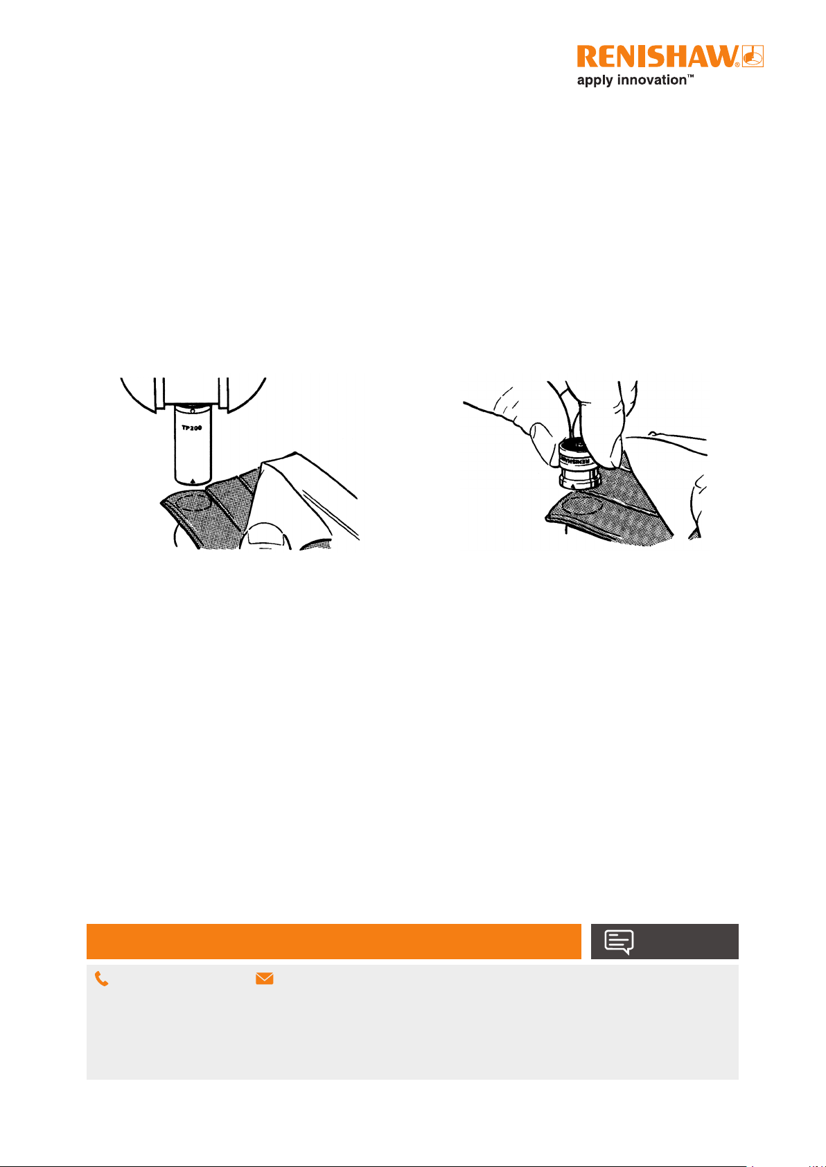
6 Maintenance
The kinematic coupling mechanism, connecting the probe body to the stylus module, incorporates precision ball / V groove seatings.
The coupling mechanism has been tested in a wide range of environments and is highly tolerant of non-metallic dust, but regular
inspection and cleaning with the CK200 material (supplied) is recommended to ensure continued high performance. Instructions for
use are included with the cleaning material (Renishaw part number A-1085-0016).
The user should determine the frequency of cleaning according to the conditions of use.
Stylus balls, threads and mating faces should be cleaned with a proprietary cleaning cloth or solvent.
Stylus modules that are not in use should be stored in spare ports in the SCR200 rack or in their transport boxes.
Before cleaning the probe body, please ensure either the power is off or that the probe body is removed from the probe head.
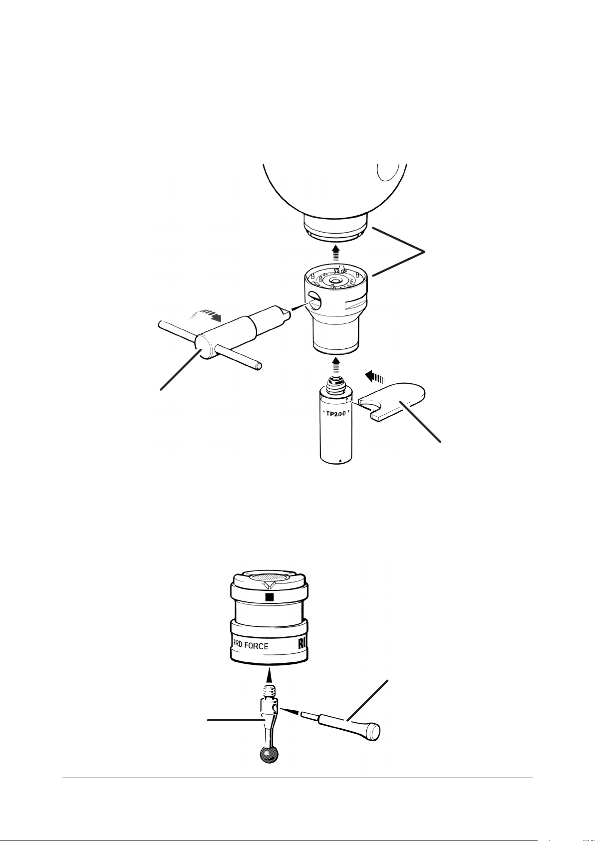
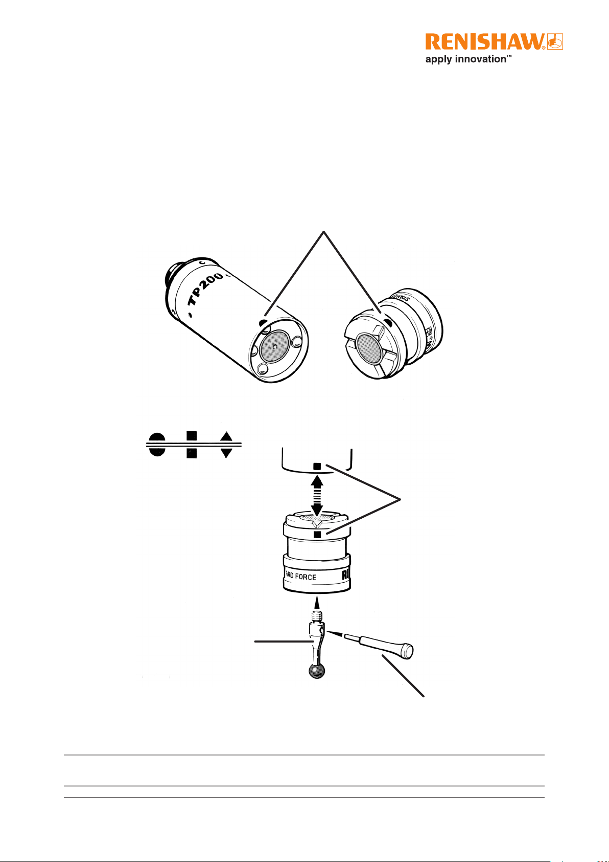
After cleaning the probe body and module re-attach the module following the instructions in the attaching stylus module section
above.
Table of contents
Other Renishaw Control Unit manuals