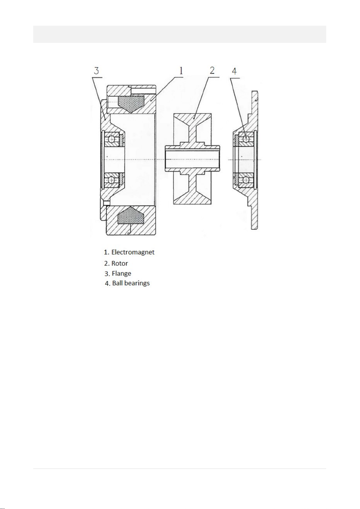
Renova PWX Series Quick guide

powder brake PWX
Assembly and maintenance manual
ITA

2
© Copyright Renova Srl, 2013. All rights reserved.

3
english - index
introduction .…………………………………………………………….…….… page 4
warnings …….…………………………………………………….…….…….….. page 4
assistance ………………………………………………..………....……………. page 4
description …………………………………………………..……………………. page 5
power supply ALPWX ………………………………………..………………. page 6
assembly procedures …………………………………………………………. page 7
assembly and overall dimension tables ..……..…………………….. page 8
costructiveness and functioning ..………………..…………………….. page 10
replacement of electromagnetic powder ..…………………………. page 11
technical datas and graphics ....…………………..……………………… page 13
warranty ..……………………..……………….…………….…..………………. page 15
index of manual revision …………....…………….…..………………….. page 16

4
introduction
The following manual is intended for installers and users of the product and provides descriptions
and explanations on the PWX powder brakes (installation and maintenance) and on all its parts
and / or options that can be supplied by Renova.
Inside you will find:
- Instructions for the correct installation of the PWX brake, and relative maintenance
- Description of the possible versions of the PWX brake with relative dimensions and dimensions
- Technical data and related tables
Since the product and Renova itself are constantly evolving in order to improve the quality and
performance of its products, Renova reserves the right to update the manuals to new versions,
without the obligation to update products already marketed and / or any previous manuals.
warnings
CAREFULLY READ THE INSTRUCTIONS AND WARNINGS IN THIS MANUAL AND KEEP THEM FOR
FURTHER REFERENCE FOR THE ENTIRE LIFE OF THE PRODUCT. IN THIS MANUAL ARE
IMPORTANT INSTRUCTIONS RELATING TO OPERATIONS AND SAFETY FOR THE INSTALLATION,
USE AND MAINTENANCE OF THE PRODUCT.
WE STRONGLY RECOMMEND ASSEMBLY OF THE DEVICE BY QUALIFIED TECHNICAL PERSONNEL
IN ORDER TO AVOID ANY RISK OF DAMAGE TO PEOPLE, THINGS OR THE PRODUCT ITSELF.
IN THE EVENT OF ANY BREAKAGE OF THE PRODUCT, THE OPERATOR SHOULD BE AWARE OF
THIS MANUAL AND THE INFORMATION INSIDE IT, KNOWING AND KNOWING TO AVOID ANY
RISKS AND / OR DANGERS, BEFORE ANY INTERVENTION BY OUR TECHNICIAN.
assistance
Renova is present all over the world with its agents and distributors.
To contact the Renova support service write to:

5
description
The PWX series electromagnetic powder brakes guarantee perfect torque adjustment and stability
over a wide speed range. The torque is produced by a special magnetic powder whose viscosity
varies according to the magnetic field generated by modulating the coil supply current. This
functional feature allows to design transmissions in which it is possible to easily adjust and
program the braking (brake) or drag (clutch) torque according to the user's needs and in a wide
range of use, from the minimum residual torque value: Mr (residual torque Mr <= 1% Mn), up to
the rated torque Mn of the brake/clutch (see Table). These clutches (brakes) can work with
continuous slip at precise defined and stable torque values, determined by the level of
electromagnetic excitation, provided that the heat dissipation is acceptable within the range
specified in the table divided by size and version.
In order to transfer the torque, therefore, a slipping condition is not necessary between the
brake/clutch input and output elements and, if the required torque does not exceed the maximum
torque for which the brake is powered, a torque transmission with rotation will occur.
synchronous between the brake / clutch input and output elements. Conversely, if the torque load
exceeds the excitation torque level, the slip will occur in an absolutely regular way, transmitting
only the set torque value. For all working modes, the static and dynamic torque coefficients are
practically identical. The output torque is independent of the speed or slip speed. The
characteristics of the powder are not sensitive to the increase in temperature in the workplace
and the clutch always has the characteristic that the torque transferred is directly proportional to
the supply current.
To adjust the braking torque Renova recommends using the ALPWX-5A module. The set torque is
maintained with an accuracy of 5%, regardless of the number of revolutions or slippage between
the brake body and the rotor. The operating rpm range is as follows:
50 - 3.000 [min-1] for brakes,
50 - 1.500 [min-1] for clutches.
ATTENTION: For clutches and brakes to work properly, their axis of rotation must
be horizontal.

6
ALPWX-5A: power module
Technical specifications
Power supply From 12V to 27V AC or from 12V to 36V DC
Set power output
Adjustable from 1A to 5A, current-stabilized output,
regulated through the reference analog inputs
Reference nominal tension 24V DC
Power outputs 24VDC 200mA for sensors power supply (ex.:
ultrasonic)
Set point auxiliary
output 10VDC 50mA (control through potentiometer 5KOhm)
Digital inputs
3 dedicated digital inputs with configurable activation
level through JP2 (0V or 24VDC)
FREE/BRAKE/DEMAG functions
Digital outputs
2 Set-point analog inputs 0-10VDC and 4-20mA
Analog outputs
2 configurable analog outputs (supplied power or set point)
Comm Interface
RS485
Jumper
JP1: RS485 termination
JP2: set up digital input activation mode
LEDs
2 for functioning and programming check
2 for activated pre-programmed functions check
Function PSW protection - Automatic Demag function – Display value
setting - Smart Dancer
Operating
temperature
+0°C / +70°C
Available versions
DIP-SWITCHES user interface (mod. ALPWX-5A-DSW)
LED DISPLAY user interface (mod. ALPWX-5A-LED)

7
assembly procedures
PWX powder brakes and clutches require a few tricks to perform a correct assembly. Rather, it is
recommended that you follow each step and check for correct execution.
Mount the brake or clutch on the shaft with the key in the appropriate seat.
Brake PWX Clutch PWX
Assembly will be performed near the centering dimension B as per drawing. In case of flanged
mounting it is important to check that the machining on the machine shoulder complies with the
centering dimensions and tolerances for the flange dimension B **. In case of assembly with anti-
rotation arm, the coupling flange of the arm to the brake must be suitably machined and fixed.
IMPORTANT: Since the brake (clutch) is symmetrical, dimension B in the drawing can be found in
both parts of the product. However, one of these faces has the coil terminals which must NEVER
be mounted towards the machine shoulder or otherwise they could short-circuit making the
brake unusable. It is therefore very important to mount the coil terminals from the outside.
ATTENTION: In case of assembly of a clutch it will be necessary to fit a support for
the clutch brushes which must work in contact with the manifold.
** If the assembly foresees a flanging through centering, it will be necessary to verify that the
mechanical workings are carried out in tolerance so as not to axially or radially stress the brake /
clutch bearings. Even in a possible case of assembly with belt or chain transmission (reduction or
multiplication ratio), it will be necessary to avoid stressing the brake/clutch bearings. As a last
step, tighten the mounting screws indicated in the drawing.
NOTE: as regards the part relating to the electronics of the brakes (clutches), we recommend, as
mentioned above, the use of our ALPWX-5A power supply which provides greater stable electrical
control.

8
brake (clutch) assembly and dimension table
standard dimensions:

9
dimensions with optional:

10
costructiveness and functioning
The PWX series of powder brakes and clutches consists of the following parts:
The PWX brake (clutch) is composed of two coaxial rotors: the coil for the generation of the
variable and controlled magnetic field is inserted in the external rotor and supports the internal
rotor through two bearings. In the air gap (distance between the internal surfaces of the two
rotors) the magnetic powder is distributed which has the property of varying its viscosity in
proportion to the variation of the magnetic field generated by the coil. The change in viscosity
translates into a change in the coefficient of friction between the two rotors, thus allowing you to
adjust the amount of resistant torque in the brake (braking force), or of the transmission torque in
the clutch (drag force). The torque transferred by the brake or powder clutch is therefore
proportional to the intensity of the coil excitation current and is easily modulated from zero to the
nominal value of the deliverable torque, this occurs for all models.

11
replacement of electromagnetic powder
The powder brake (clutch) does not require any particular maintenance other than a periodic
replacement of the magnetic powder which allows the brake to operate correctly.
The replacement of the powder must be performed in a few steps:
1) Remove the screws from the flange of the
side opposite the coil terminals. Turn the
brake upside down and place it on two
spacers of 50 mm located outside the
centering flange. Using a manual press,
apply the force necessary to disassemble
the internal rotor from the support bearing
on the axis of the internal rotor.
Alternatively, use a rubber mallet.
However, the use of an aluminum pin /
shaft is recommended. Remove the flange from the rotor. Then remove all traces of
residual dust from the flange, rotor and internal brake body. It is recommended to
carefully degrease and dry each internal part of the brake with alcohol or dry solvent
using rubber gloves. Reposition the brake on the shims with the open side facing
upwards, avoiding any interference with the coil terminals so as not to damage them.
2) Pour half of the magnetic powder
inside the brake, trying to distribute it
evenly as close as possible to the walls
along the entire internal diameter.
Then insert the rotor into the bearing
in its seat by applying the necessary
force by means of a manual press or by
means of a hammer with rubber stops,
taking care to interpose on an
aluminum pin to avoid damaging the
rotor hole.

12
3) Pour the residual magnetic powder into the
rotor trying to distribute it evenly in the
external area along the entire diameter
4) Reassemble the flange on the rotor
by acting with a force directly on the
bearing and then on the flange as
soon as the bearing reaches the outer
edge of the rotor. Check the
correspondence of the holes of the
closing screws on the flange with the
threaded holes on the brake body, place the flange on the brake, then fix the flange to
the body with the screws previously removed.
Below is a table with the PWX models available in Renova with indications on the quantities of
electromagnetic powder to be used

13
technical datas and graphics

14

15
warranty
Renova srl guarantees this device against any defects relating to materials and manufacturing for a
period of 12 months from the date of delivery of the brake itself.
In the event that, during the period covered by the guarantee, the device exhibits malfunctions,
please contact the representative of the Company in the country of origin, or, in the absence of
these, Renova srl directly.
The warranty includes spare parts and labor, but the shipping costs for delivery or collection of the
device are exempt.
The warranty becomes invalid in the following cases:
• Improper use of the product
• Incorrect installation
• Lack of maintenance
• Modifications or interventions with non-original components or with personnel not authorized
by Renova srl
• Total or partial non-compliance with the instructions
• Exceptional events
Once the warranty period has expired, technical support will be carried out by the assistance
network which will carry out repairs according to the rates in force.

16
Index of manual revision
Rev. n. Revision date Description of the chenges made

17
note

18
note

Renova srl – viale Rimembranze 93 – 20099 Sesto San Giovanni (MI) Italy
tel.: +39.02.2700.7394 – fax: +39.02.2570.8635
www.renova-srl.com – email: support@renova-srl.it
This manual suits for next models
39
Table of contents
Other Renova Industrial Equipment manuals
Popular Industrial Equipment manuals by other brands

Carrier
Carrier 1184802 installation instructions

Bühler technologies
Bühler technologies GAS 222.17 Assembly, installation and operation instructions

Powrmatic
Powrmatic HEM-NVx Series User, Installation & Servicing Manual

BIRD
BIRD 8640A930-1 Operation manual

GMW
GMW 5451 user manual

SCE
SCE ENVIRO-THERM SCE-HE18W120V user manual