Table of Contents
1 Introduction.....................................................................................................8
1.1Validity
....................................................................................................8
1.2Target group
............................................................................................8
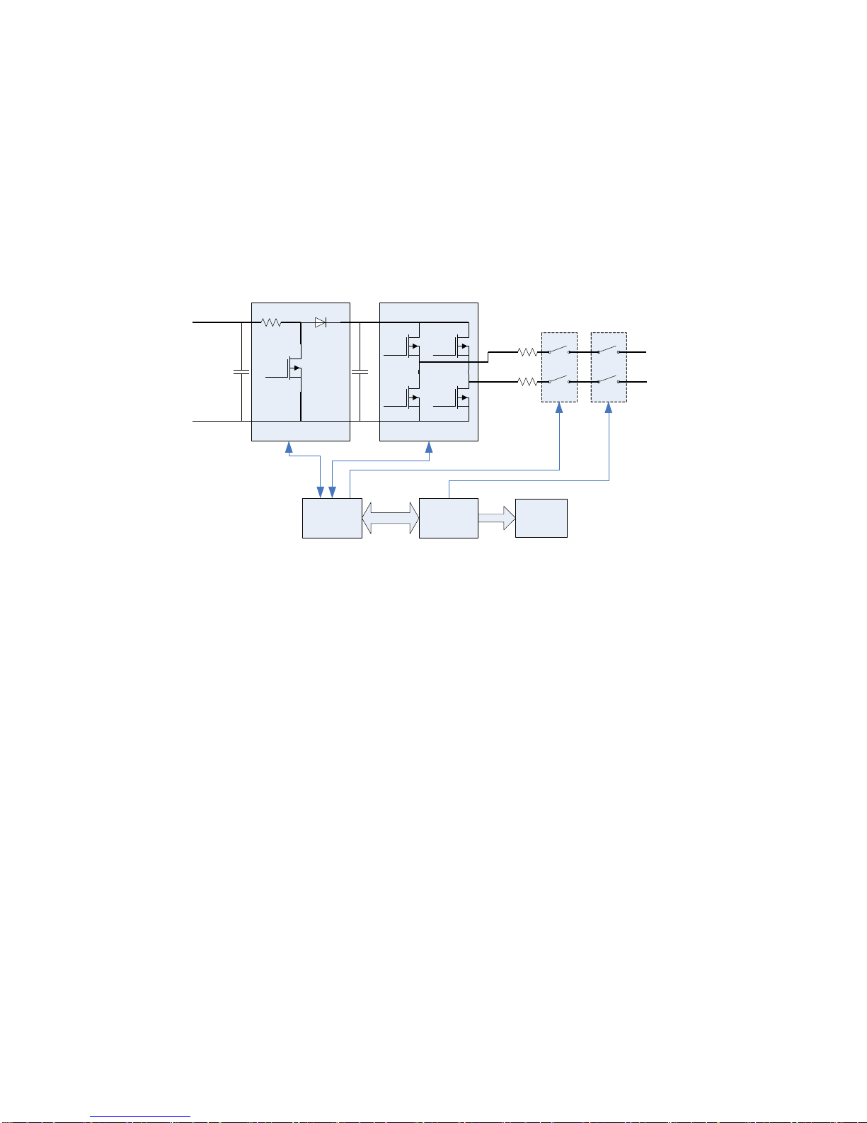
1.3Product overview
.....................................................................................9
1.4Feature Overview
..................................................................................13
1.5Safety
...................................................................................................13
1.5.1Protection and criterion
.................................................................13
1.5.2 Safety instructions
........................................................................16
1.5.3SymbolsontheTypeLabel
...........................................................18
1.6Installation Overview
..............................................................................19
2 Unpacking and Inspection............................................................................20
2.1Scope ofDelivery
...................................................................................22
3 AC Voltage Configuration.............................................................................23
3.1OpeningtheDigiwattsUnit
......................................................................23
3.2Locating Internal Components
.................................................................24
3.3 Configuring theAC Voltage
.....................................................................25
4 Mounting.......................................................................................................26
4.1Choosing aMounting Location
................................................................26
4.2 Dimensionsand Required Clearances
.....................................................28
4.3Mounting Procedure
.......................................................................30
4.3.1Mounting theWall-Mounting Screw
.........................................30
4.3.2 Mounting the Digiwatts Unitto theWall Bracket
........................31
5 Wiring the Digiwatts unit...............................................................................32
5.1SequenceofConnecting
........................................................................35
5.2OpeningtheDigiwatts
............................................................................36
5.3 Wiring theAC Output
..............................................................................37
5.3.1AC ConnectionRequirement
.........................................................37
5.3.2 ConnectingtheAC Wires
..............................................................38
5.4 Wiring the DC input
................................................................................39