Rentokil Luminos 3 Plus User manual

1
MODEL – Luminos 3 Plus
Wall Mounted Model
INSTRUCTION MANUAL

2
IMPORTANT SAFETY INSTRUCTIONS
WARNING – When using electric appliances, basic precautions should always be
followed, including the following:
a) Read all the instructions before using the appliance.
b) To reduce the risk of injury, close supervision is necessary when an appliance is
used near children.
c) Do not contact moving parts.
d) Only use attachments recommended or sold by the manufacturer.
e) Do not use outdoors.
f) - To disconnect, turn all controls to the off position, then remove plug from outlet.
–Do not unplug by pulling on cord. To unplug, grasp the plug, not the cord.
–Unplug from outlet when not in use and before servicing or cleaning.
–Do not operate any appliance with a damaged cord or plug, or after the appliance
malfunctions or is dropped or damaged in any manner. Return appliance to the
nearest authorized service facility for examination, repair, or electrical or mechanical
adjustment.
g) To reduce the risk of electrical shock, do not put this product in water or other liquid.
Do not place or store appliance where it can fall or be pulled into a tub or sink.
h) Always unplug before replacing the lamp. Replace bulb with same type rated 15
Watts.
i) Connect to a properly grounded outlet only. See Grounding Instructions.
INSTRUCTIONS PERTAINING TO A RISK OF FIRE, ELECTRIC SHOCK, OR
INJURY TO PERSONS.
We hereby declare that Models Luminos 3 Plus and Luminos 3 to conforms covering
the appliance provisions of applicable US Federal requirements, including 21 CFR,
Chapter 1, Subchapter J, Radiological Health.
CAUTION, Risk of UV exposure, keep a safe distance of 1,19 feet from this unit
whilst illuminated.
WARNING – Skin or eye damage may result from directly viewing the lamps. This
product is provided with an interlock/micro switch to reduce the risk of excessive UV
radiation. Do not defeat the purpose or attempt to service without removing the cover
completely.
"WARNING - To reduce the risk of electric shock, unplug before cleaning or
servicing."

3
CAUTION
The unit must not be installed where dangerous concentrations of inflammable or
explosive substances are likely to be present in the air.
The product is intended for commercial indoor use only but is not suitable for use in
barns, stables and similar locations. The device is not constructed for use outdoors or
in wet locations. To avoid risk of fire or electrical shock, do not use where it may be
exposed to water or direct sunlight, including roofed, but open porches.
ATTENTION
Replacing the control film, starters and lamps may be performed by the user. All other
repairs and maintenance must be performed by qualified personnel.
Disconnect the product from the power source when not in use, before servicing,
when changing tubes and cleaning.
Store the unit indoors when not in use - out of reach of children.
Do not abuse the mains cable- never carry product by the cable or pull it from socket.
Keep cable from heat, oil and sharp edges. Never allow the cable to hang in front of
the cover.
Do not insert foreign objects into this product.
SAVE THESE INSTRUCTIONS

4
GROUNDING INSTRUCTIONS
This product is equipped with an appropriate 3-core cable and 3 pin earthing type plug
to fit the proper earthing type socket. To reduce the risk of electric shock, the plug
must be plugged into an appropriate outlet that is properly installed and EARTHED.
Consult a suitably qualified person if the earthing instructions are not completely
understood, or if in doubt as to whether proper earthing exists.
EXTENSION CORDS
EXTENSION CORDS ARE NOT TO BE USED WITH THIS UNIT.
This appliance must be grounded. In the event of malfunction or breakdown,
grounding provides a path of least resistance for electric current to reduce the risk of
electric shock. This appliance is equipped with a cord having an equipment-grounding
conductor and a grounding plug. The plug must be plugged into an appropriate outlet
that is properly installed and grounded in accordance with all local codes and
ordinances.
DANGER – Improper connection of the equipment-grounding conductor can result in
a risk of electric shock. The conductor with insulation having an outer surface that is
green with or without yellow stripes is the equipment-grounding conductor. If repair or
replacement of the cord or plug is necessary, do not connect the equipment-
grounding conductor to a live terminal. Check with a qualified electrician or
serviceman if the grounding instructions are not completely understood, or if in doubt
as to whether the appliance is properly grounded. Do not modify the plug provided
with the appliance – if it will not fit the outlet, have a proper outlet installed by a
qualified electrician.

5
TYPE OF UNIT
The electronic Flying Insect Control
System (FICS) does not use high voltage
grids. Instead flying insects are captured
on a replaceable adhesive film. Insects
are attracted to the unit by 3 x 15 watt
ultra-violet lamps and the film prevents
their escape.
UNPACKING THE UNIT
Each unit is carefully packed before
leaving the production factory to ensure it
reaches you in perfect working order.
Please be sure to remove all packing
from the unit before installation and
check the unit for any transit damage.
LOCATIONS
The attraction of the unit to flying insects
is partly dependent on the intensity of the
competing daylight or artificial light. The
correct location of the unit is most
important in order to achieve the
maximum efficiency. Where possible,
follow these guidelines:
1. The unit can be mounted on any
suitable wall except for those
locations where the sight of captured
insects would be undesirable. In
these situations the unit should be
mounted above head height.
Wherever the unit is placed there
should be enough clearance in front
and above (at least 60mm) the front
cover to allow it to open up for ease
of servicing.
2. Place the unit as far as possible from
windows, to minimize the competition
from daylight.
3. DO NOT place the unit directly over
sources of heat since these may
damage the cable installation.
4. DO NOT position directly over areas
where food is prepared or uncovered
food is stored.
5. CAUTION, Risk of UV exposure,
keep a safe distance of 1,19 feet
from this unit whilst illuminated.
Unlike high voltage units, this system
may be placed in food production areas,
providing easy access is possible and
that sheathed shatterproof tubes are
fitted.
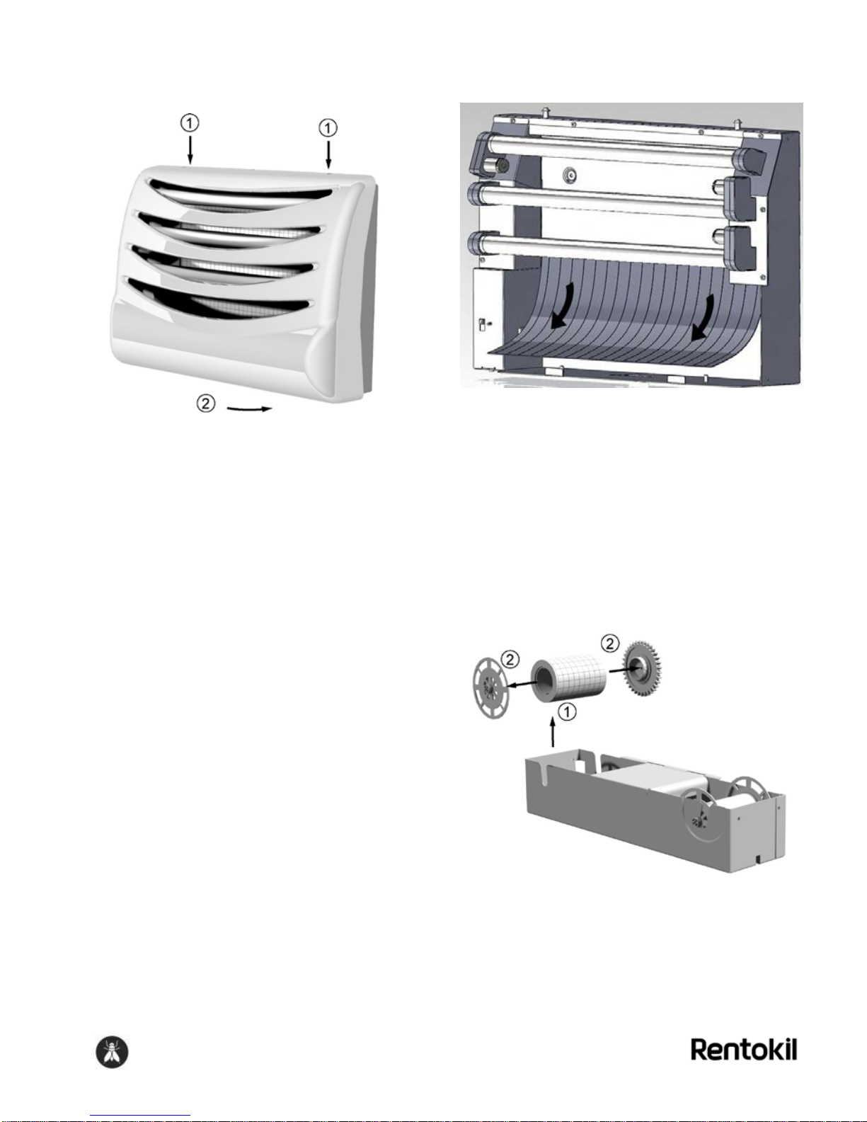
ASSEMBLY & INSTALLATION
Luminos 3 Plus is a wall-mounted unit.
To fix to the wall first unclip the cover
from the backplate and lift off the catch
tray.
Locate the unit on the wall in the selected
position, making sure that the top edge is
horizontal, and that there is an
unobstructed distance of at least 200mm
(8”) above the top fixing hole centers,
then mark the wall and drill holes for
screw plugs. Number 8 or 10 screws, at
least 40 mm (1½”) long are
recommended. Insert four plugs into the
holes and screw the unit firmly to the
wall. Do not over-tighten the screws.
Refit the catch tray and cover.

6
CONNECTION TO THE POWER
SOURCE
Installation of this unit should only be
carried out by a qualified electrician. The
unit is supplied with power cable, which
must be connected to a suitable outlet.
The cable should be plugged into a
standard power socket or fused spur.
The unit must NOT be connected into
a lighting circuit.
1. Check that the mains voltage on the
unit label is correct for your supply.
2. Ensure that the supply is fused at 3
Amps maximum
3. Connect the unit to the mains by the
cable provided, which is terminated
with a plug connector.
4. Should rewiring of the unit be
necessary, this must be made with
cable sheathed with polychloroprene
(Type SJT)
5. Should it be necessary to remove the
plug connector to make an
alternative connection to the mains
supply, ensure that the following
color code is strictly adhered to: -
BLACK - Live; WHITE - Neutral ;
GREEN/YELLOW - Earth.
6. Make sure that the supply cable is
out of reach of children
The severed plug connector should be
destroyed to prevent accident.
WARNING
ENSURE THAT THE UNIT CAN BE
BOTH SWITCHED OFF AND
ELECTRICALLY ISOLATED BY
DISCONNECTION FOR
MAINTENANCE.
SETTING UP AND OPERATION
Remove the cover of the unit. (Fig 1.)
Figure 1
Loading / changing the adhesive film is
best carried out with the catch tray fully
removed from the unit and placed on a
suitable work surface.
Figure 2
Remove the catch tray by lifting the tray
vertically away from the base so that the
location pins are free, then, pull the tray
forwards, clear of the unit. (Fig. 2)

7
In high infestations Luminos 3 Plus,
offers the option to use a glueboard.
Remove paper from the glue board and
slide up the chassis behind the bulbs.
(Fig. 3 & 4)
Figure 3
Figure 4
Fit two end caps into the glue roll and fit
into the right hand side of the catch tray.
Pull sufficient paper from the reel to
reach the drive reel and manually wind
the paper on until the glue on the upper
surface is securely fitted. Manually
advance the film until the adhesive
coating reaches the drive shaft keeping
the roll under tension (Fig. 5)
Note: The glueboard should only be
used if there is a heavy infestation of
flies.
Figure 5
Place the Catch Tray back into the unit;
holes in the tray align with studs in the
base. Ensure that the gear is to the left,
and meshes with the motor gear. (Fig. 6)
Figure 6
.

8
.
Refit the cover securely to the unit. (Fig.
7)
Figure 7
THE TIMER FUNCTION
The unit’s timer is programmed by the
manufacturer to give a service period of
3 months. A new section of film will
automatically wind into place every 60hrs
(2½ days). On the left hand side of the
unit is a switch that allows the timer to be
set to either 30, 60 or 120 hrs.
FILM & GLUEBOARD REPLACEMENT
At each routine service, switch off the
unit, disconnect from the mains and
remove the cover. (Fig. 1) Check that
there is still film between the spools
inside the unit. If there is, advance the
film until it leaves the left spool and
totally winds onto the right spool.
If a glue board has been installed this
should be removed and replaced.
First remove the Cover and lift out the
Catch Tray as described in the section
‘Setting Up And Operation’. (Fig. 1 & 2)
If required, release the glue board from
the central tab and slide out and discard
(or retain for counting). (Fig. 8)
Figure 8
If required, refit a new glue board by
sliding it up the chassis side channels
behind the lamps onto the central tab.
(Fig. 4)
Lift the left spool clear of the Catch Tray.
Remove the end cap and gear off the
used glue roll. Discard the used roll. (Fig.
9)
Figure 9
Lift the right end spool from the Catch
Tray. Replace one end spool cap with
the gear, refit on the left hand side of the

9
Catch Tray. Fit two end caps into the
glue roll and fit into the right hand side of
the Catch. Pull sufficient paper from the
reel to reach the drive reel and wind the
paper on until the film is securely fitted
and tensioned. (Fig. 5)
Replace the Catch Tray with the gear to
the left of the unit (Fig. 6)
Refit the cover to the unit. (Fig. 7)
CLEANING
Note: Disconnect the unit from the
power supply before cleaning
Remove any dead insects from the
enclosure. Clean all surfaces that come
into contact with the film using white
spirit and remove all traces of adhesive.
Clean the outside of the unit case with a
paper window cleaning cloth.
U.V. LAMP REPLACEMENT
Although to our eyes the appearance of
the lighted lamps may not change, their
UV light output will reduce with time. To
maintain the efficiency of the unit the
three UV lamps must be replaced
annually.
Unplug the mains power cable and open
the front of the unit. Skin or eye damage
may result from directly viewing the
lamps. This product is provided with an
interlock/micro switch to reduce the risk
of excessive UV radiation. Do not defeat
the purpose or attempt to service without
removing the cover completely.
Carefully remove the lamp holder covers
at each end of the UV lamp. The inner
halves will be positioned on the lamps
during removal so care must be taken to
retain them.. Rotate each lamp a quarter
turn and withdraw the lamps forward and
remove the loose lamp holder covers.
(Fig. 10)
Figure 10
To install new lamps reverse the above
lamp removal procedure. The lamp
holder cover inner halves must be fitted
over the UV lamps prior to fitting of the
lamps – the outer halves must be fitted
after the lamps have been located in
their holders. Please take care to ensure
the small lamp tube holder cover parts
are retained during service visits. Only
replace lamps with lamps of the type
supplied with the unit i.e. PHILIPS
LIGHTING B.V., Type TL 15W 15W/Act,
with shatterproof sheathing
If a lamp fails to light, a faulty starter
normally causes the problem. The
starters are situated in holder beside the
lamps. To replace a starter, turn each a
quarter turn anticlockwise and withdraw.
Then replace with a new one. Note: The
3 lamps are controlled by 3 starters type
FS-2

10
FAULT FINDING
If the motor does not operate at the set
time period and the UV lamps are on, the
probable cause will be that the fuse
protecting the control circuit board has
blown. To replace this fuse, first
disconnect the supply cable to the unit,
then, remove the motor cover plate
(situated bottom left) from the unit by
unscrewing the 5 self tapping screws, 2
on the front, 2 on the back and 1 on the
base. Carefully lift the motor cover plate
off, taking care not to damage internal
wiring. Carefully remove the fuse located
at the inboard end of the control circuit
board and replace with a 20mm, 1 amp,
quick blow fuse.
SCHEMATIC WIRING DIAGRAM

11
SPECIFICATION
Power Supply: 120V / 60 Hz ~
Power Consumption: 91mA @ 120V 60Hz
Internal Fuse: 20mm 1 Amp Quick Blow.
Size Inch (mm): W 20 (510) x H 15 (380) x D 6,1 (154)
Weight lb (kg) Boxed: 16,8 (7.6) / Unit: 10,1 (4,6)
Conforms to the relevant sections of:
E345204
UL 73
EPA NUMBER???
F

12
Exploded View - Parts Identification.

13
PARTS LIST
No. Description
1.Cover Assy
2.Lamp Holder
3.Lamp Holder Cover-Back
4.Lamp Holder & Base Cover-Back
5.Lamp Holder Cover-Front
6.Lamp Holder & Base
7.Lamp Holder & Base Cover-Front
8. Starter
9. Ballast FL 15W
10.M2x12mm Screw
11.Module LH
12.Mirco Switch
13.Mirco Switch Cover
14.M2 Lock Nut
15.Ballast Cover
16.Conduit
17.Back
18.Strain Relief Bush
19.M3x8 Screw
20.Bush
21.Washer
22.M4 Lock Nut
23.ψ4.2 INT. Tooth Washer
24.Wiring Harness
25.M4x8 Screw
26.Module RH
27.Lamp
28.End Spool
29.Terminal Block
30.M3x12 Screw
31.Core Extrusion
32.Drive Gear
33.M5 Wing Nut
34.Film Guide
35.Motor
36.PCB
37.34 Tooth Gear
38.Motor Cover
39.Catch Tray

14
Manufactured for Rentokil
made in Vietnam
Number:363204
Revision 1.0
30-01-2012
Table of contents
Other Rentokil Insect Control Equipment manuals
Popular Insect Control Equipment manuals by other brands

Isotronic
Isotronic ISOKAT Insect Pro Instructions for use

VOSS.farming
VOSS.farming Tabanus-Trap edge Installation & operating instructions

MistAway
MistAway Gen II operating manual

BioSensory
BioSensory Mosquito 'Cognito operating instructions

Airofog
Airofog U260 manual

DynaTrap
DynaTrap DT1210 owner's manual