The lamps in this unit produce ultraviolet (UV) light, which can
cause skin or eye damage if viewed directly for a long period.
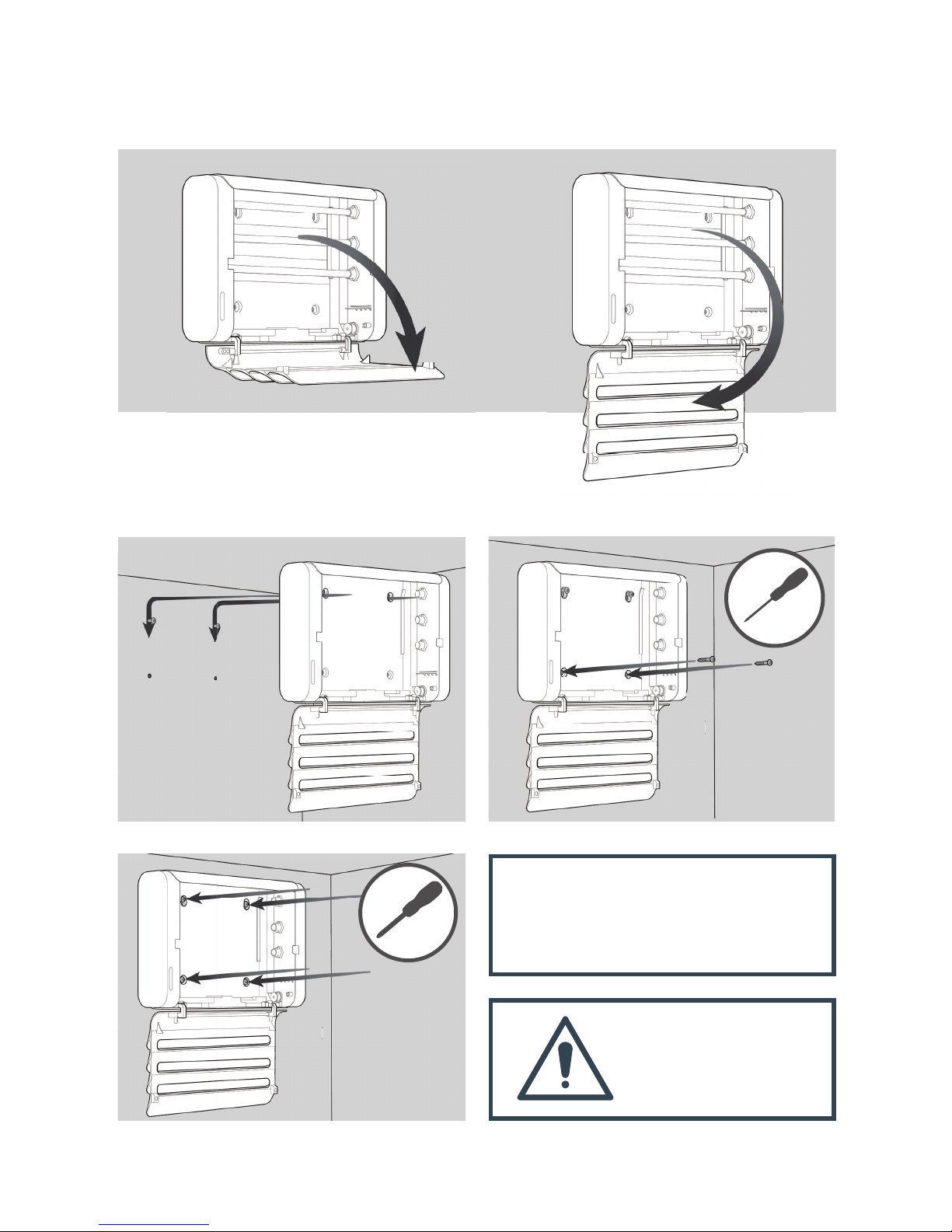
Only fit the correct type of UV lamps in the unit.
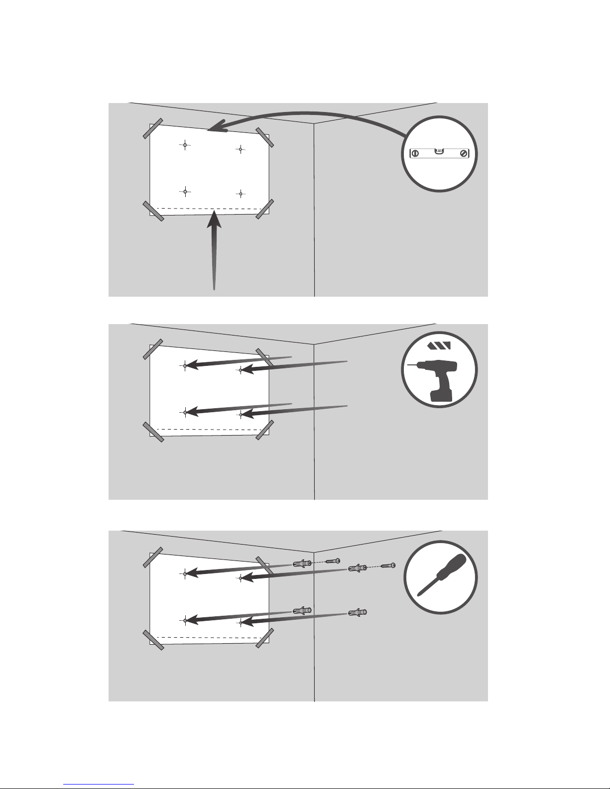
The unit shall be installed and serviced by individuals with
appropriate qualifications and/or experience in accordance
with national regulations in the country of operation and
installation.
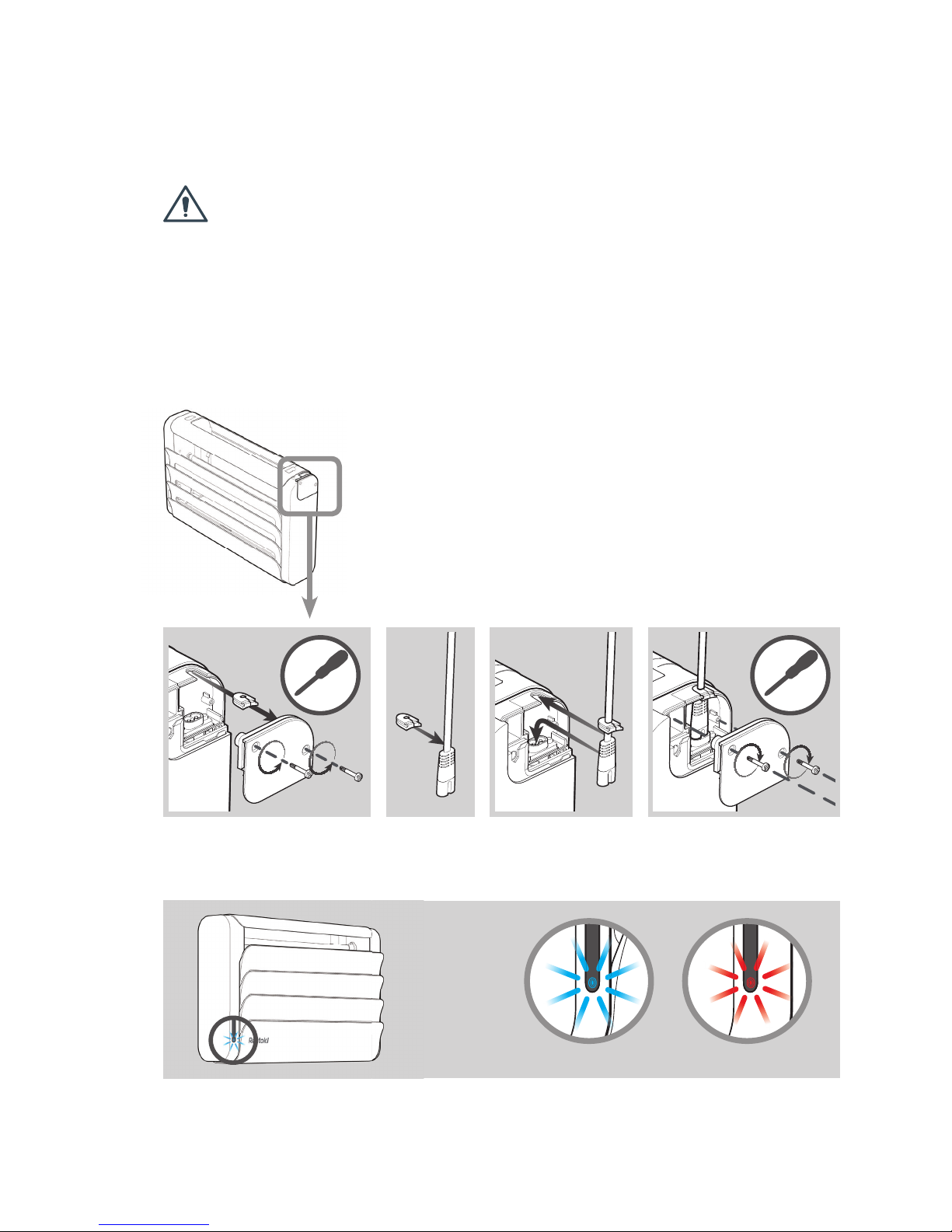
Disconnection from the mains is provided by means of a
supply cord fitted by a plug. Protect the mains cable from
damage. If the mains cable is damaged, do not use the unit.
The cable must be replaced by the manufacturer, its service
agent, or similar qualified persons.
Do not insert foreign objects into the unit.
Do not use an extension cable with this unit.
Only personnel with appropriate skills and training must install
or service this unit.
Do not install this unit in areas where dangerous
concentrations of inflammable or explosive substances may
be present in the air.
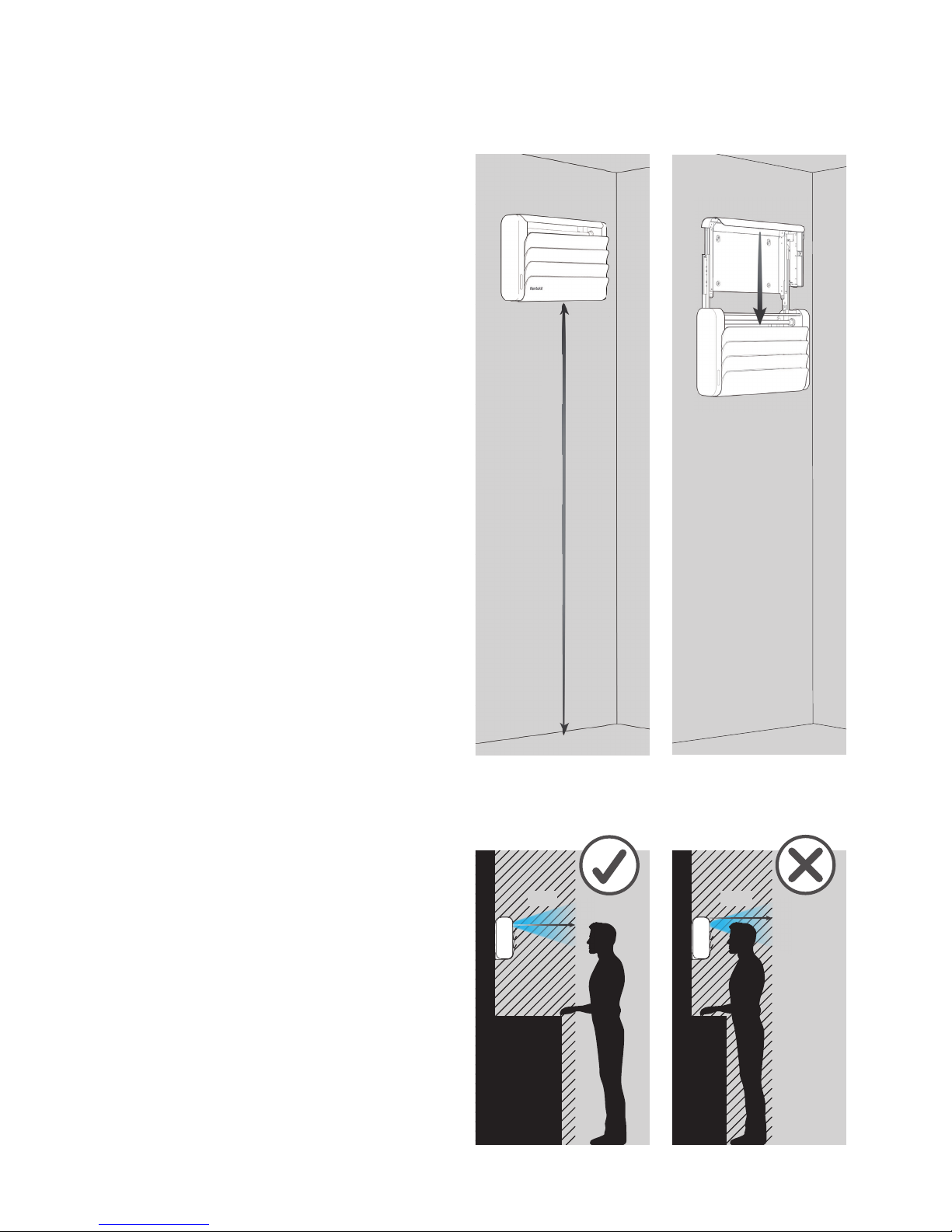
Only install this product indoors in a dry location that is
shielded from direct sunlight. Do not install the unit in a barn,
stable, or similar location.
Install the cable such a way to prevent the exposition of the
cable to UV radiation from UV Lamps
Children or personnel with reduced physical, sensory or
mental capabilities, or personnel who lack experience or
knowledge, must not use this unit, unless they are supervised
by a person responsible for their safety. Children must not
play with this unit. The appliance is to be kept out of reach of
children.
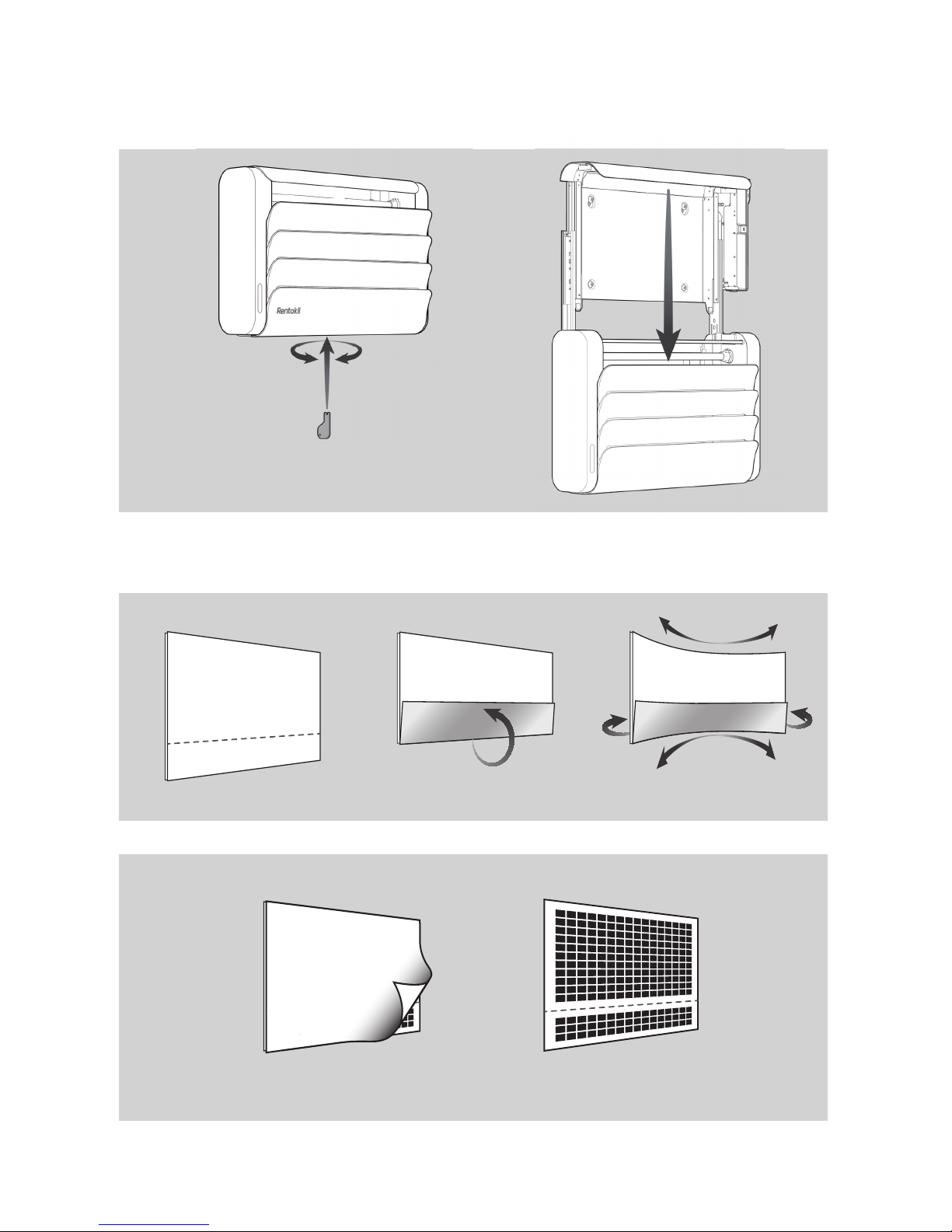
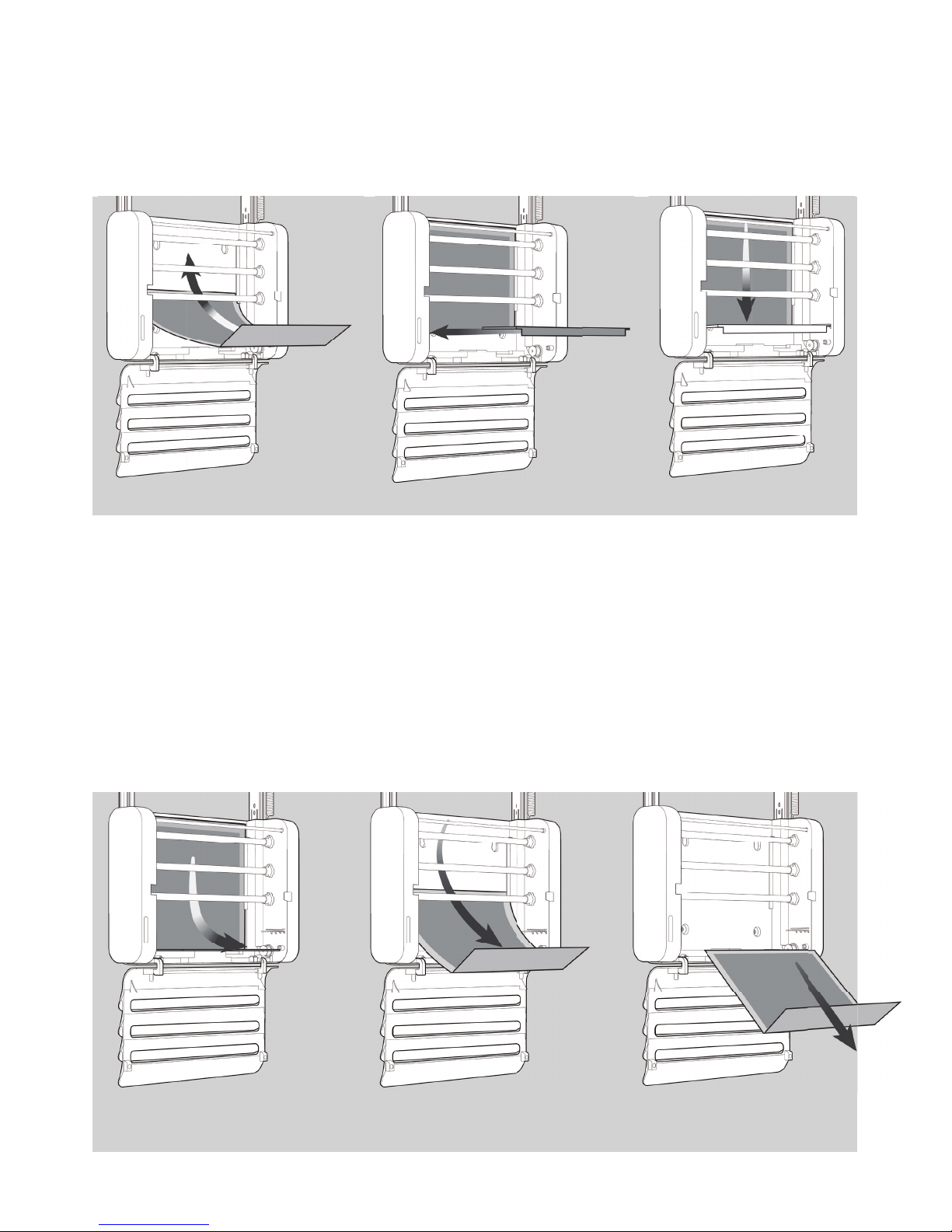
Users can perform the maintenance tasks described in this
document. Users must not perform any other repairs or
maintenance.
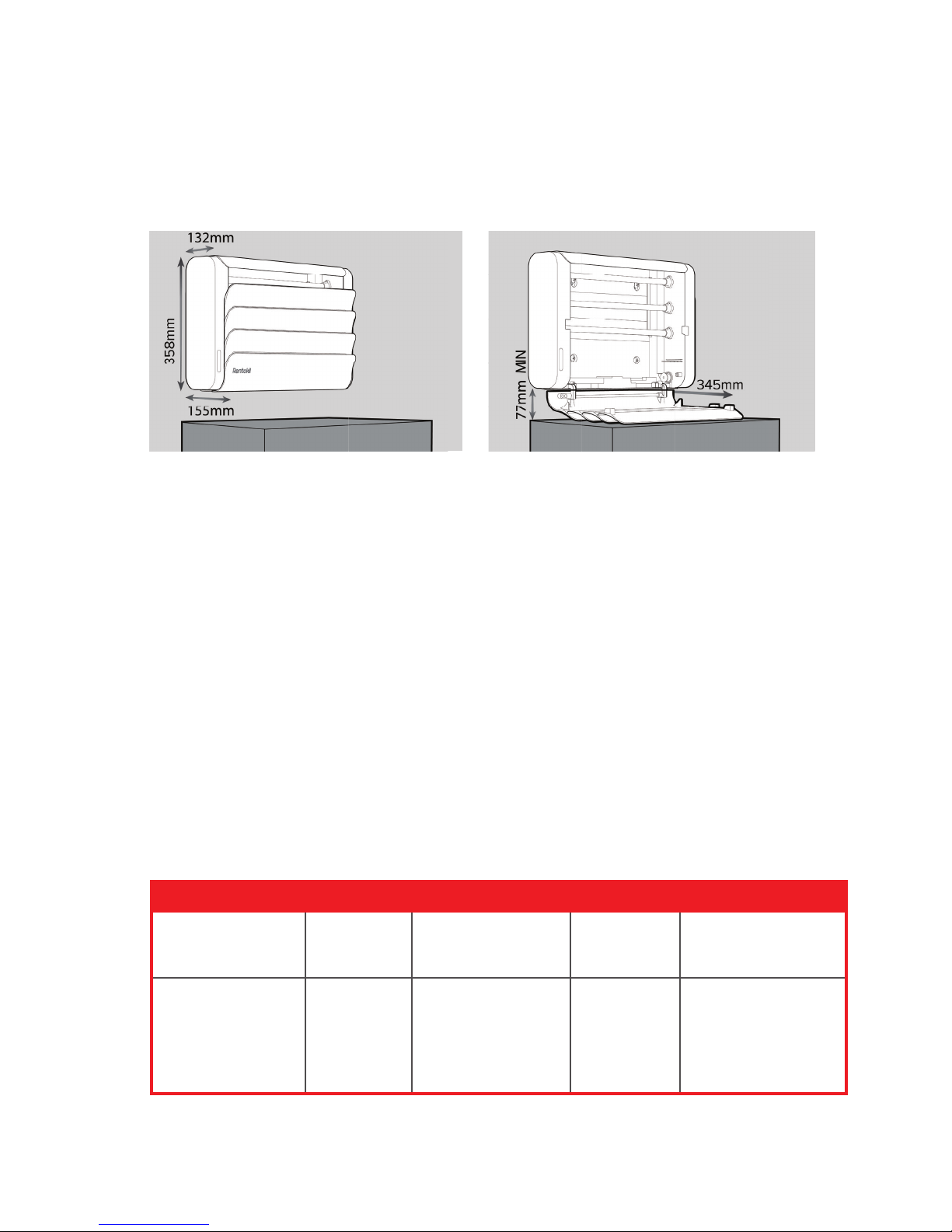
Only Lamps specified in Section 20: Accessories and Spares,
to be used with this product.
Warning
Caution
Attention
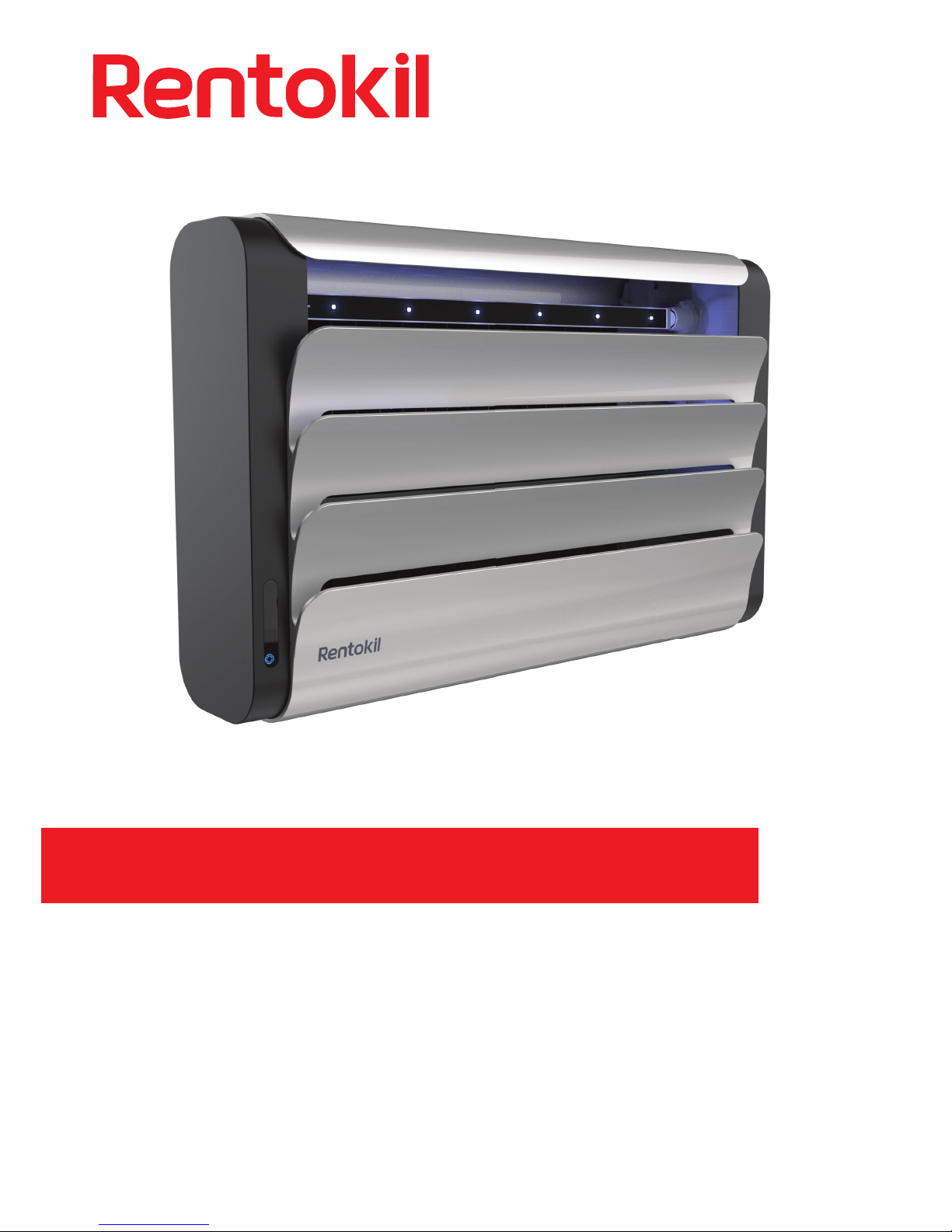
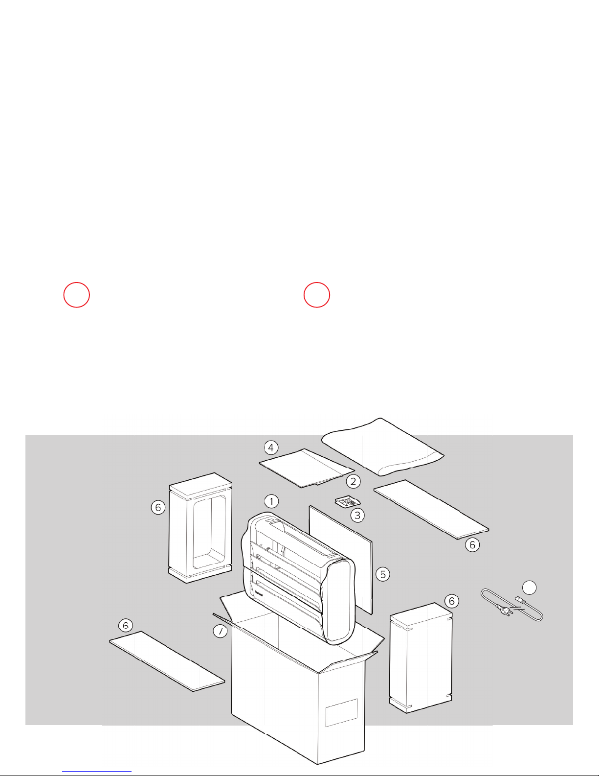
1. Safety
SAVE THESE
INSTRUCTIONS
WARNING Skin or eye damage may result
from directly viewing the light produced by the
lamp in this apparatus. To safeguard always
ensure installation manual and manufacturers
recommendations are followed.
CAUTION Risk of UV exposure. Ensure product is installed
to ensure no person is likely to be within 0.5 metres of the
unit while illuminated. GSD-200802-1