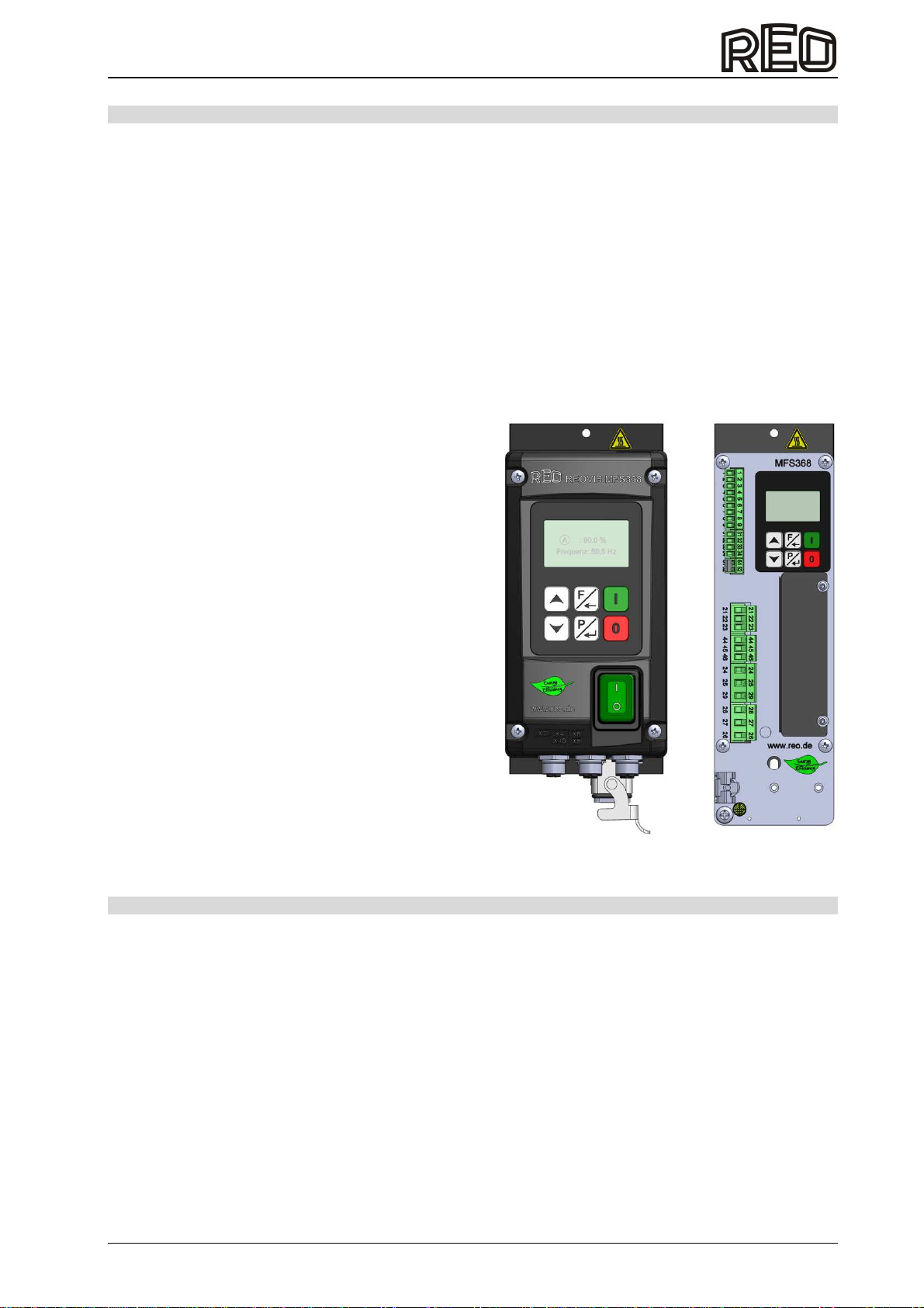
REOVIB MFS 368
Operating instructions
2
Table of contents
Safety instructions for the user..................................................................................................................... 3
Declaration of Conformity ............................................................................................................................. 6
Changes / Copyright..................................................................................................................................... 6
1.0 General................................................................................................................................................... 7
2.0 Function.................................................................................................................................................. 7
2.1 Track control ....................................................................................................................................... 8
2.2 Operation with two speeds (2
nd
setpoint for coarse/fine switching).................................................... 8
2.3 Control inputs and outputs.................................................................................................................. 9
2.3.1 Enable input..................................................................................................................................9
2.3.2 Sensor input for track control .......................................................................................................9
2.3.3 External setpoint........................................................................................................................... 9
2.3.4 Control output status relay ........................................................................................................... 9
2.3.5 Control output 24 VDC Timeout (IP54)........................................................................................9
2.3.6 Ready relay .................................................................................................................................. 9
2.3.7 Control output 24 VDC Valve (IP54) ............................................................................................9
2.3.8 Thermal switch ............................................................................................................................. 9
2.4 Touch panel ......................................................................................................................................10
3.0 Structure ............................................................................................................................................... 11
3.1 IP54...................................................................................................................................................11
3.2 IP20...................................................................................................................................................11
4.0 Technical data ......................................................................................................................................11
4.1 Load supply requirements ....................................................................................................................12
4.2 Terminal details ....................................................................................................................................12
4.3 Temperature of protective housing.......................................................................................................12
4.4 Coolant type..........................................................................................................................................12
4.5 Current consumption ............................................................................................................................12
4.6 Warning signs.......................................................................................................................................12
5.0 Ordering code (Standard units) ............................................................................................................13
6.0 Possible settings...................................................................................................................................14
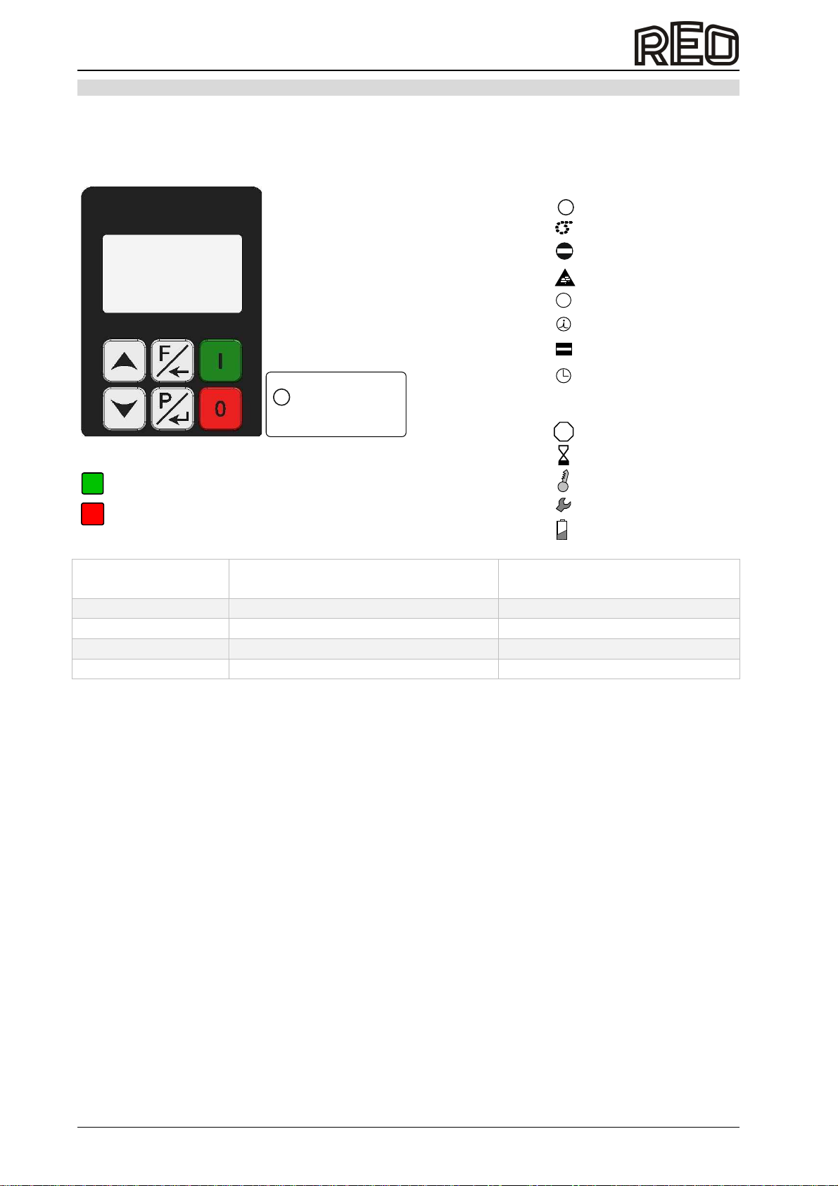
7.0 Operating elements ..............................................................................................................................16
7.1 Setting behaviour..............................................................................................................................16
7.1.1 Parameter setting example............................................................................................................17
7.1.2 External setpoint example .................................................................................................................17
8.0 Commissioning.....................................................................................................................................18
8.1 Preparatory measures.......................................................................................................................18
8.2 Operating frequency of the feeder coils............................................................................................18
8.3 Measurement of output voltage and output current..........................................................................18
9.0 Settings.................................................................................................................................................19
9.1 Notes on controller mode..............................................................................................................19
9.2 Mounting the accelerometer..........................................................................................................19
9.3 Correlation between acceleration and vibration amplitude...........................................................21
9.4 Determining the resonant frequency.............................................................................................21
9.5 Commissioning the control unit in control mode ...........................................................................22
10.0 Troubleshooting ..............................................................................................................................23
11.0 Housing version connection ...............................................................................................................24
12.0 Connection of control cabinet version ................................................................................................25
13.0 Dimension drawing.............................................................................................................................27
14.0 Assembly instruction...........................................................................................................................30
A 1.0 Accessories / Options .......................................................................................................................31