Rescue 42 podRUNNER User manual

Rescue 42, Inc.
P.O. Box 1242 Chico, CA 95927
(888) 427-3728 • (530) 891-3473
Rescue42.com • ThePodRunner.com
PodRunner™ by Rescue 42, Inc. – Celebrating 25 Years of Innovation
1
Quick Start Guide – Loading
Position the vehicle’s tow hitch over solid, level ground.
Remove the Hitch Adapter from the Chassis Bed and insert the Receiver Tongue into the hitch of vehicle. Secure with
the Anti-Rattle Hitch Pin ensuring that the threaded block is on inserted side.
Set the Height Adjustment of the Hitch Adapter.
Pull the Hitch Adapter’s Mounting Box up & away from the vehicle to seat the PitchLok Pins in the LOAD position.
Raise the SatRunner by rotating the Crank Handle CLOCKWISE to elevate the Mounting Pin above the Hitch
Adapter. Roll into position with the Mounting Pin above the Mounting Box Receiver Tube.
Turn the Crank Handle COUNTER-CLOCKWISE to lower the Mounting Pin into the Hitch Adapter until the
Mounting Tabs drop and lock into their respective holes.
Continue lowering until the weight begins to transfer to the vehicle’s suspension. STOP turning the handle. Give the
Unit a firm push towards the vehicle. The PitchLok Pins will slide down into the TRANSPORT position.
Connect the Runner’s Chassis 4-pin connector to the vehicle’s 4-pin receiver and test for proper operation of the Stop,
Turn, and Taillights.
After securing the unit into the TRANSPORT Position, continue raising the Lower Frame until the Mounting Box
locks on the tabs of the Lower Frame, then a ¼ to ½ a turn more to add compression securing it to the Hitch Adapter.
LOAD
TRANSPORT
TAB

Rescue 42, Inc.
P.O. Box 1242 Chico, CA 95927
(888) 427-3728 • (530) 891-3473
Rescue42.com • ThePodRunner.com
PodRunner™ by Rescue 42, Inc. – Celebrating 25 Years of Innovation
2
Remove Leg Pins (A) from both sides of the Tail Axle assembly.
Rotate the Tail Axle upwards.
Reinsert Leg Pins into the UP-position holes.
Exercise caution to not pinch the Brake Lines.
Remove the Steering Lock Pin (A) and both Leg Pins (B).
Rotate the axle half-way up, then rotate the steering handle counterclockwise 180°.
Align the steering link and lock tab holes (C) and insert the steering lock pin (A).
Rotate the wheels all the way into the UP position.
Reinsert both leg pins (B) into UP position holes.
Use the Red Safety Lanyard to secure the handle.
Verify SatRunner chassis lights are fully functional before traveling.
A
UP
A
B
UP
C
180°

Rescue 42, Inc.
P.O. Box 1242 Chico, CA 95927
(888) 427-3728 • (530) 891-3473
Rescue42.com • ThePodRunner.com
PodRunner™ by Rescue 42, Inc. – Celebrating 25 Years of Innovation
1
Quick Start Guide – Unloading
Position the vehicle (and the mounted SatRunner) over firm, level ground.
Disconnect and stow the 4-pin light connector.
Set the SatRunner’s Parking Brake.
Remove both leg pins (A) from the UP-position holes.
Rotate the Tail Axle downwards.
Insert both leg pins (A) locking the Tail Axle into the DOWN position holes.
Unclip the Red Safety Lanyard securing the Pull Handle.
Remove both leg pins (B) and steering lock pin (C).
Rotate the Steering Axle downwards approximately halfway and then rotate the steering handle clockwise 180°.
Align the steering link and tie rod holes (D) and insert the steering lock pin (C).
Insert both leg pins (B) into DOWN position holes.
A
DOWN
A
C
B
180°
C
D
DOWN
B

Rescue 42, Inc.
P.O. Box 1242 Chico, CA 95927
(888) 427-3728 • (530) 891-3473
Rescue42.com • ThePodRunner.com
PodRunner™ by Rescue 42, Inc. – Celebrating 25 Years of Innovation
2
Turn the Crank Handle CLOCKWISE, to lower the wheels, until they meet the ground.
a. Once the wheels meet the ground, there will be resistance in the Crank Handle as the weight shifts from the
vehicle to the SatRunner.
b. Continue turning the Crank Handle CLOCKWISE, until the PitchLok Pins pop loose and the Mounting Pin comes
out of the Mounting Box.
If the PitchLok Pins do not release (typically due to lack of lubrication), push the unit towards the vehicle.
Alternate between rotating the Crank Handle and pushing the unit toward vehicle, until the PitchLok Pins
release.
Continue elevating until the Mounting Pin is clear of the Mounting Box, unlock the parking brake and move the unit
away from the vehicle.
If the vehicle needs to leave, remove Hitch Adapter from the vehicle and store it in the bed on the Lower Frame.
Be sure the unit is clear of any obstruction and then turn the Crank Handle COUNTER-CLOCKWISE to lower the
Upper Frame onto the Lower Frame.
The unit should only be moved with the Upper Frame fully lowered to prevent tipping.
Roll the SatRunner to the desired location for operation.

Rescue 42, Inc.
P.O. Box 1242 Chico, CA 95927
(888) 427-3728 • (530) 891-3473
Rescue42.com • ThePodRunner.com
PodRunner™ by Rescue 42, Inc. – Celebrating 25 Years of Innovation
1
Quick Start Guide – Stabilizers
Remove the orange and red stabilizer cables from storage drawer.
Remove Red Safety Lanyards securing stabilizer legs and rotate legs to
the ground. Raise chassis with Crank Handle approximately 12”.
Anchor orange cable to key slots on the long Lower Frame rails, see
Figure 1. Orange cable mount keyholes are on the bottom of the Lower
Frame below Cable Slot label. Anchor opposite end to slot in stabilizer
leg. Repeat for remaining orange cables.
Lower chassis Pull Handle to ground before connecting red cables.
Anchor red cable to key slot on the lower frame short end rail and
cross over to opposing leg, see Figure 2. Cable mount keyways are
on the face of the short rails. Repeat for other red cables.
Lower the chassis with Crank Handle by rotating
counterclockwise. This will force weight onto legs and slide them
outwards until cables are taught, see Figure 3. Ensure feet slide
smoothly and are not caught on a rough surface or obstacle. Lower
chassis enough to stabilize where the wheels are not bearing any
weight.
If SatRunner is not close to level due to uneven ground, reverse process
to take weight off the stabilizers and extend leveling feet on the
downhill side. Retighten the cables.
Rotate chassis handle upright and secure with Red Safety Lanyard.
KEY HOLE
Figure 1
Figure 2
Figure 3
Figure 4

Rescue 42, Inc.
P.O. Box 1242 Chico, CA 95927
(888) 427-3728 • (530) 891-3473
Rescue42.com • ThePodRunner.com
PodRunner™ by Rescue 42, Inc. – Celebrating 25 Years of Innovation
1
Quick Start Guide – Satellite
Deploying
1. Set up your SatRunner in an appropriate location
on solid, level ground with a clear view of the
Southern sky.
2. Deploy stabilizer legs as shown on Stabilizer
Setup Guide. Fully stabilize before proceeding
with satellite deployment.
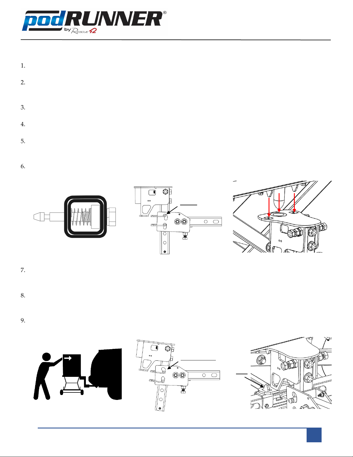
3. Turn on the red Master Power switch to the
SatRunner, see Figure 1 red circle.
4. Wait 10 seconds, and then push the green
Winegard Power button, see Figure 1 green
circle. The satellite computer screen Figure 1 blue
rectangle will light up and go through a
diagnostic check.
5. Allow the Winegard controller to boot up and
establish a dual GPS heading. When the green
“Find Satellite” button comes on, you are ready
to continue. During this process, set-up your
generator or shore power connections (if
applicable).
6. Press the green “Find Satellite” button on the
Winegard controller screen (see picture). The
satellite signal acquisition system is automatic
from this point.
7. The Winegard dish will begin moving and search
for the satellite. This process can take anywhere
from 3 to 10 minutes. When the red “Stow
Antenna” button comes on, you are connected to
the satellite, but broadband will take a few more minutes. When the “signal” message on the bottom
left of the screen reads “Signal Online”, allow another minute for the Cradlepoint to prioritize traffic to
the satellite. You are now connected to the High-Speed Ka-band ViaSat satellite broadband.
Stowing
1. Stowing is the reverse of deploying. Push the red “Stow Antenna” button to start the process.
Figure 2
Figure 3
Figure 4

Rescue 42, Inc.
P.O. Box 1242 Chico, CA 95927
(888) 427-3728 • (530) 891-3473
Rescue42.com • ThePodRunner.com
PodRunner™ by Rescue 42, Inc. – Celebrating 25 Years of Innovation
1
Quick Start Guide – Mast
Deploying the Mast
Make sure the two Mast Mounting Clamps are tight.
If guying mast, do so now.
Securely attach antennas to mast top.
Undo the top mast lock and use your hands to extend the smallest diameter pole.
Pivot the locking lever back down to secure the extended section of the mast.
Repeat step 3 for the rest of the sections, as needed.
a. DO NOT overextend the mast poles!
b. There are red lines to show you are close to the end of the pole.
c. The Mast should not ever be extended to a point that the Red Ring is showing on the pole. The red ring
must be below the cutout for the clamp.

Rescue 42, Inc.
P.O. Box 1242 Chico, CA 95927
(888) 427-3728 • (530) 891-3473
Rescue42.com • ThePodRunner.com
PodRunner™ by Rescue 42, Inc. – Celebrating 25 Years of Innovation
2
Guying the Mast
Retrieve the three Mast Guy Line Stakes.
Find three spots about 12’ from the Mast. They should be roughly 120° apart.
Drive the stakes into the ground at a ~45° angle, away from the Mast.
Slide Guy Ring around mast.
Obtain the Guy Cables from the Drawer inside the Enclosure.
Attach an end to one of the three points on the Guy Ring.
Hook a Rope Tensioner to each Stake and pull a line of Rope through,
leaving it loose to extend the Mast.
Extend the Mast, as necessary.
Once the Mast is extended, pull the excess further through the Easy -
Tensioner to make the Guy Cables Taught.
a. The Mast should not be angled.
b. After tensioning the Guy Cables, securely fasten excess.
Rope Tensioning Fitting
Pull the rope through as
shown to tension

Rescue 42, Inc.
P.O. Box 1242 Chico, CA 95927
(888) 427-3728 • (530) 891-3473
Rescue42.com • ThePodRunner.com
PodRunner™ by Rescue 42, Inc. – Celebrating 25 Years of Innovation
1
Quick Start Guide – Initial Setup
Turn on all circuit breakers located on the rear of the PCM. (1 – 4)
a. For 1 and 2 rotate the yellow lever upwards until clicked into position.
b. For 3 and 4 flip the toggle switches up.
Connect Shore AC power to Shore AC Inlet (1) and rotate Power Inlet
Selection Switch to Shore (2).
Set Source Power Switch to AC on front of the PCM.
Charge unit completely until Battery Monitor synchronizes to the full state
(approximately 1 hour).
Compensate the compass as necessary per manufacturer specifications.
The Cradlepoint router is preconfigured for the SatRunner. If other networking
changes are required consult an IT professional.
Perform initial setup on generator. Follow manufacturer specifications. This
includes, but not limited to:
a. Fill with oil
b. Fill with gasoline
c. Check for leaks
1
2
3
4
1
1
2
Figure 2
Figure 5
Figure 3
Other manuals for podRUNNER
1
Popular Automobile Accessories manuals by other brands

Kogan
Kogan KAPWB12V14A quick start guide

Caltrend
Caltrend TY458 installation instructions

aFe Power
aFe Power F1-03003 instruction manual

Whispbar
Whispbar K1010 instructions

Diamondback
Diamondback 270 installation guide

Cequent Towing Products
Cequent Towing Products Signature Series operating instructions