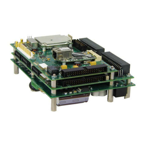
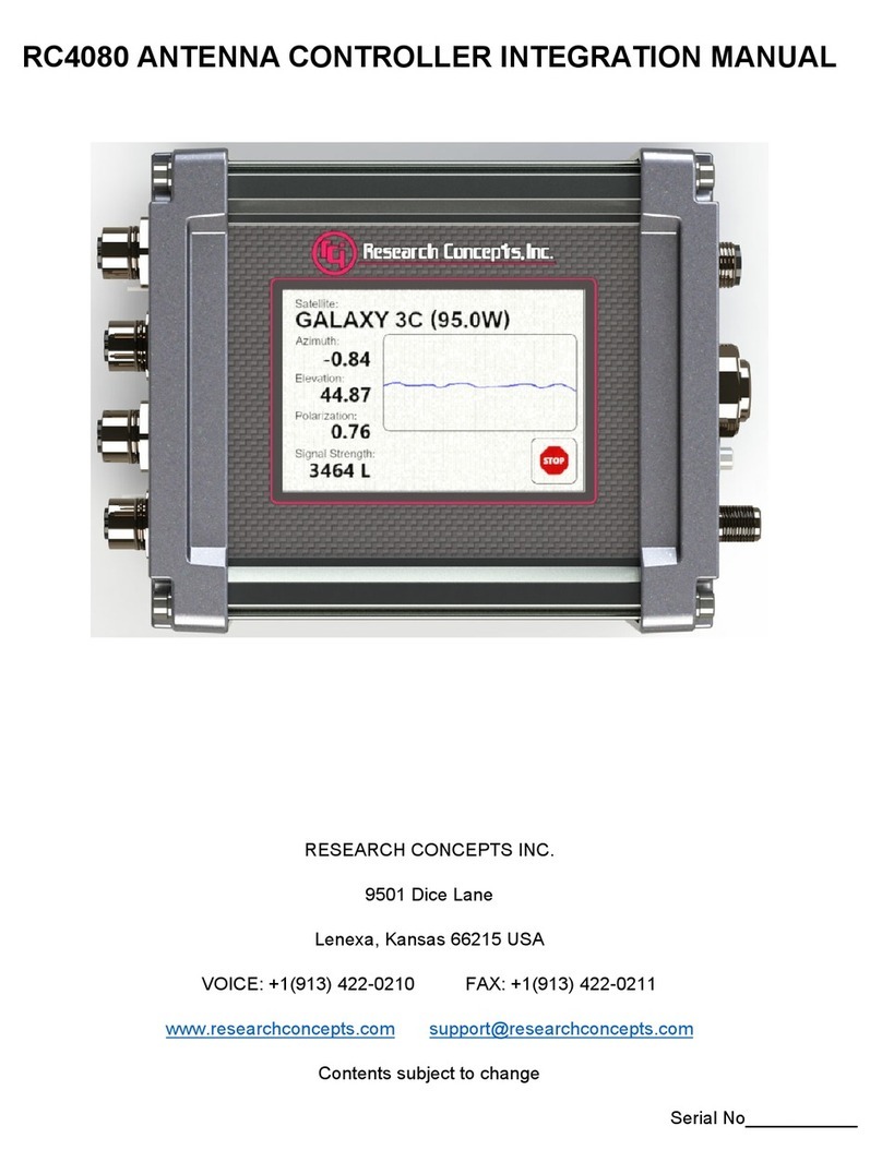
RESEARCH CONCEPTS RC4000 User manual

RC4000 Antenna Controller Appendix REM Remote Control Option
REM-1
APPENDIX REM – REMOTE CONTROL PROTOCOL
Last Revised: 09 FEB 2014
Software Version: 0.05
This appendix describes the configuration required and the commands used to implement the remote
control interface for the RC4000 antenna controller. It is provided as a supplement to the “baseline”
RC4000 manual. Sections in the baseline RC4000 manual are referred to when data specific to the
remote control option are described.
NOTE: RC4000 software is built on a per-mount basis. Some commands may not be available on all
devices.
Revision History
01 FEB 2014
Document added to version control system.
ECG
09 FEB 2014
Added move to nominal angle command for polarization.
ECG

RC4000 Antenna Controller Appendix REM Remote Control Option
REM-2
1.0 THEORY OF OPERATION
Overview
The RC4000 supports a variety of remote monitor and control commands. The controller functions as a
slave device within a network. The network is expected to consist of one master and multiple slaves
communicating over a single interface (or “bus”). Each slave is internally configured with a unique
address.
Message Protocol
Message format and protocol over the bus is a derivative of IBM's binary synchronous communications
protocol (BISYNC). The master station sends a command over the bus to all slave devices. The device
whose address is specified in the command message carries out the requested commands, and then
replies with a response message containing the result. A device does not respond if the command does
not containing its address. This prevents bus contention caused by more than one remote device
communicating over the bus at the same time. NOTE: Even if the antenna controller is the only device on
the network, it still must be addressed.
Data Format
All data should be in 7-bit ASCII format. The control character subset 00-1F (hex) is reserved for
message control. The printable ASCII characters 20-7F (hex) are used for address, command and data
characters.
Message Format
Command messages begin with the STX (Start-of-text) byte followed by a remote address, a command
byte and multiple data bytes. The ETX (End-of-text) byte is sent following the last data byte, and the
message is terminated by a Checksum character. Response messages are identical to command
messages in format with the exception of the ACK (Acknowledge) or NAK (Not Acknowledge) byte at the
start of the message instead of STX. Figure 1 illustrates the format of the command and response
messages. A command or reply message may have a variable length.
Command Message
STX ADDR CMD D1D2D3… DNETX CHKSUM
Response Message – Command Acknowledged
ACK ADDR CMD D1D2D3… DNETX CHKSUM
Response Message – Command Not Acknowledged (Unable To Execute or Incorrect Command)
NAK ADDR CMD ETX CHKSUM
Figure 1 – Message Format

RC4000 Antenna Controller Appendix REM Remote Control Option
REM-3
Message Delimiters
A command message begins with STX (02 hex). A reply begins with ACK (06 hex) or NAK (15 hex)
depending on the result of the command execution. All messages end with the ETX (03 hex), the ASCII
End-of-text control character, followed by the Checksum byte.
Address Byte
The device address (ADDR) must be a valid ASCII printable character between 49 (31 hex) and
111 (6F hex); thus, 63 addresses are possible.
Command Byte
The command byte (CMD) immediately follows the device address and specifies one of several possible
commands for a particular device.
Checksum Byte
The last character of any message is the Checksum byte (CHK). This character is simply the bit-by-bit
exclusive OR of all characters in the message starting with the STX character through the ETX character.
This forms a Longitudinal Redundancy parity check over the entire message.
Message Timing
The NAK or ACK reply does not signify that a function has actually taken place, but only that the message
was received and understood. The user should query the controller later to see if the command was
actually carried out, or is still in progress.
Command Restrictions
All RC4000 devices will respond to a command "0" (30 hex) with 6 data bytes of ASCII characters in the
following form:
ACK ADDR 30h 4 K D1. D2D3ETX CHKSUM
where D1.D2D3are ASCII characters representing a software version number (e.g. 1.12).

RC4000 Antenna Controller Appendix REM Remote Control Option
REM-4
State Diagram
The state diagram illustrated below presents the implementation of the slave device that guarantees the
proper transfer and processing of communication messages sent by a master controller. Each state that
the device can assume is represented graphically as a circle. A single-digit number is used within the
circle to identify the state. All transitions between states are represented graphically by arrows between
them. Each transition is qualified by conditions that must be true in order for the transition to occur.
Figure 2 – SA Bus Protocol State Diagram
State Descriptions
•State 1 – Idle State
oThe device is ready to receive a new message. A device always powers on in State 1.
oThe device will enter State 2 only if the STX byte is received.
•State 2 – Addressed State
oThe device is waiting to receive the address byte.
oThe device will enter:
State 3 if the received address byte is correct.
State 1 if the received address is not correct.
oThe device will stay in State 2 if the STX byte is received.

RC4000 Antenna Controller Appendix REM Remote Control Option
REM-5
•State 3 – Data State
oThe device is engaged in receiving the command data from the master.
oThe device will enter:
State 4 if the ETX byte is received signifying the end of data in the message.
State 1 if the STX byte, an invalid byte, or the incorrect number of data bytes is
received.
•State 4 – Data Error State
oThe device is waiting to receive a Checksum byte.
oA slave will enter:
State 5 if the received Checksum byte equals the LRC value computed during
message reception.
State 1 if the received Checksum byte does not equal the LRC value computed
during message reception.
•State 5 – Command Execute State
oThe device begins execution of the received command.
oThe device begins sending the appropriate response message to the master.
oThe device will enter State 1 only when the entire response has been transmitted.

RC4000 Antenna Controller Appendix REM Remote Control Option
REM-6
2.0 CONFIGURATION
Electrical Interface
The RC4000 can interface with a variety of physical interfaces including Ethernet, RS-232, or RS-422.
Refer to section 2.1.2.3.9 of the baseline RC4000 manual and supplemental appendix IP for more
information on interfacing with an Ethernet network. Refer to section 2.1.2.2.4 of the baseline RC4000
manual for more information on interfacing with a serial network.
Communications Parameters
When the RC4000 is expected to be controlled via a RS-232 or RS-422 network, the controller’s baud
rate and address must be set. These values can be specified via the REMOTE CONTROL configuration
screen.
ENABLED:1 CONFIG-REMOTE
ADDRESS: 50 MODE:1
BAUD_RATE:6 JOG:20
REMOTE CONTROL <0>DISABLED <1>ENABLED
ENABLED: REMOTE CONTROL <0>DISABLED <1>ENABLED
This item allows the user to disable the ability to remotely control the RC4000. This may prove useful if
the user wants to only operate from the front panel.
ADDRESS: BUS ADDRESS <49-111>
This item allows the user to specify an unique bus address for the RC4000. The default address is 50.
BAUD RATE: BAUD <1-3 2-6 3-12 4-24 5-48 6-96>( x100)
This item allows the user to choose one of six possible baud rates from 300 to 9600. The default
baudrate is 9600.
MODE: REMOTE MODE <0-RS232 1-RS422>
This item allows the user to select RS232 or RS422/RS485 operation. The RC4000 is shipped from the
factory configured for RS-232 operation
JOG: REMOTE JOG HOLD <1-40>
This configuration item exists to allow the RC4000 to adjust to the required key repeat rate from the
computer sending the remote front panel commands. This value will have to be adjusted to match the
latency of different computers implementing a “remote front panel” scheme.
The REMOTE JOG HOLD value is used to jog movements when the RC4000 is operating in MANUAL
mode and being commanded via a remote front panel. The entered number multiplied by 1/40 of a
second represents how long a remote front panel jog command will last. For example, a value of 20
corresponds to a hold period of 0.5 seconds.
If the value is too low, manual movements will be jerky as the operator holds down a jog key from the
remote front panel. In this case the RC4000 sees a jog key from the remote front panel but the hold timer
expires before another jog key command is received.
RC4000 Antenna Controller Appendix REM Remote Control Option
REM-7
3.0 DETAILED OPERATION
RC4000 Online/Offline Reply
The RC4000 software must include a remote control option to process commands. If remote control is
not available, and a valid message is received (correct format, address, Checksum, etc.), the offline reply
is sent to the host. This reply has the following format:
byte 0 ACK
byte 1 A RC4000 address
byte 2 CC command code of the received message
byte 3 'F' ASCII 'F', for offline.
byte 4 ETX
byte 5 Checksum
RC4000 Unrecognized Commands – NAK Reply
If a valid message is received but the command code is unrecognized or unavailable, or if an error
occurred while processing the command data, a NAK reply is sent to the host. Additional failure
information may be available for specific commands. The NAK reply has the following format:
byte 0 NAK
byte 1 A RC4000 address
byte 2 CC command code of the unrecognized message
byte 3 ETX
byte 4 Checksum
RC4000 Command Acknowledged – ACK Reply
In many cases, if a command is received but no response is required, a standard ACK reply is sent to the
host. The standard ACK reply has the following format:
byte 0 ACK
byte 1 A RC4000 address
byte 2 CC command code of the acknowledged message
byte 3 ETX
byte 4 Checksum

RC4000 Antenna Controller Appendix REM Remote Control Option
REM-8
Command Set
The following table lists the available RC4000 remote commands.
Each command is detailed in the paragraphs listed below.
Table 1 – Command Set List
CODE (hex)
COMMAND
PARAGRAPH
30
Device Type Query
3.1
31
Device Status Poll
3.2
32
Auto Move2
3.3
33
Azimuth / Elevation / Polarization Jog
3.4
34
Polarization
3.5
35
Query Name
3.6
36
Miscellaneous
3.7
37
Reflect Display
3.8
38
Reserved
39
Write Satellite Data
3.9
3A
Read Satellite Data
3.10
3B
Write Two Line Element Data
3.11
3C
Read Two Line Element Data
3.12
3D
Write IESS-412 Data1
3.13
3E
Read IESS-412 Data1
3.14
3F
Read Pulse Count
3.15
40
Extended Device Status Poll
3.16
41
Remote Locate
3.17
42
Remote Store
3.18
43
Write Signpost Data
3.19
44
Read Signpost Data
3.20
45
Read Navigation Data
3.21
46
Write Navigation Data
3.22
47
Jog with Minimal Reply
3.23
48
Remote Key Press
3.24
49
Reserved
4A
Reserved
1 – not yet implemented in RC4000
2 – implemented in software version 0.05
Each command is detailed in paragraphs 3.1 on. The next few paragraphs describe characteristics
common to all RC4000 commands.

RC4000 Antenna Controller Appendix REM Remote Control Option
REM-9
3.1 Device Type Query Command
The SA Bus specification requires that command character 30h must trigger the return of the six
character device type string. The message format for this query will be ...
byte 0 STX
byte 1 A RC4000 address
byte 2 30h 30 hex – the device type query command code
byte 3 ETX
byte 4 checksum
The reply to this query will consist of 11 bytes ...
byte 0 ACK
byte 1 A RC4000 address
byte 2 30h the device type query command code
bytes 3,4 “4K” controller type
bytes 5-8 '”A.BC” version number – example: 1.22
byte 9 ETX
byte 10 checksum
3.2 Device Status Poll Command
The SA Bus specification requires that command character 31h cause a device to return status
information. The reply to this command includes azimuth, elevation and polarization position, current
satellite name, as well as limit, alarm and drive status information. The status poll command message
consists of 5 bytes and the format is:
byte 0 STX
byte 1 A RC4000 address
byte 2 31h the status poll query command code
byte 3 ETX
byte 4 checksum
The response to this command will consist of 52 bytes, which will be a combination of ASCII and binary
data fields. The binary data will be placed in the lower nibble of a byte whose higher nibble will be
initialized to a value which will make the result an ASCII character. The idea with this response is to be
able to reproduce the information presented on the LCD to the user when manual mode is active. The
format of the response is:
byte 0 ACK
byte 1 A RC4000 address
byte 2 31h the status poll query command code
bytes 3-12 sat_name This field will contain the satellite name in upper case letters. If
the name does not occupy the entire field the name will be left
justified and the string will be padded with blanks. If a satellite
name is not currently displayed, this field will contain blanks.
byte 13 not used reserved for future use, currently initialized to 0100$0000b.

RC4000 Antenna Controller Appendix REM Remote Control Option
REM-10
Device Status Poll Command (continued)
byte 14-19 azimuth position
This field will contain the formatted azimuth position
-180.0 to 180.0. If the analog to digital converter detects an
error this field will contain ‘******’.
NOTE: If the primary azimuth sensor is the fluxgate compass,
this field will display a value from 0.0 to 359.9 in bytes 14-18.
Byte 19 will display either a “M” or “T” to indicate whether the
value in bytes 14-18 represent a M(agnetic) or T(rue) heading
value.
byte 20-25 elevation position
This field will contain the formatted elevation position,
-180.0 to 180.0. If the analog to digital converter detects an error
this field will contain ‘******’.
byte 26-31 polarization position
This field will contain the formatted polarization position -180.0 to
180.0. If the analog to digital converter detects an error this field
will contain ‘******’.
byte 32 azimuth limits -- binary data
7 6 5 4 3 2 1 0
0 1 0 0 $ 0 A B C
A ‘0’ in a bit position implies that the antenna is not at the limit, a
‘1’ in the bit position implies that the antenna is at the limit. Here
is the mapping of bit positions to the limits ...
.
A – Azimuth Clockwise
B – Azimuth Counterclockwise
C – Azimuth Stow
byte 33 elevation limits -- binary data
7 6 5 4 3 2 1 0
0 1 0 0 $ 0 A B C
A ‘0’ in a bit position implies that the antenna is not at the limit, a
‘1’ in the bit position implies that the antenna is at the limit. Here
is the mapping of bit positions to the limits ...
.
A – Elevation Up
B – Elevation Down
C – Elevation Stow

RC4000 Antenna Controller Appendix REM Remote Control Option
REM-11
Device Status Poll Command (continued)
byte 34 polarization limits -- binary data
7 6 5 4 3 2 1 0
0 1 0 0 $ 0 A B C
A ‘0’ in a bit position implies that the antenna is not at the limit, a
‘1’ in the bit position implies that the antenna is at the limit. Here
is the mapping of bit positions to the limits ...
.
A – Polarization Clockwise
B – Polarization Counterclockwise
C – Polarization Stow
byte 35 polarization equipment and display status code – binary data
7 6 5 4 3 2 1 0
0 1 X X $ Y Z Z Z
where ‘XX’ is ...
00 if a rotating feed is not present in the system
01 if a single port rotating feed is present in the system
10 if a dual port rotating feed is present in the system. A dual
port rotating feed can simultaneously receive both horizontally
and vertically polarized signals.
where ‘Y’ is ...
0 if polarization movements are not allowed.
1 if polarization movements are allowed.
Discussion – The ‘Y’ field described above only contains
meaningful data when TRACK mode is active. Polarization
movement is not allowed during a TRACK mode peaking
operation. If a polarization operation occurs while peaking the
antenna the peak obtained may not be reliable. If a ‘go to’ H or
V polarization command is received via the serial port the
controller will execute the command after the peaking operation
is completed. The reply to the ‘go to’ command will be an ACK.
A polarization jog command which is received during a peaking
operation will not be registered and executed later. The reply to
the command will be a NAK.
where ‘ZZZ’ is ...
000 if the ‘H' polarization code is displayed
001 if the 'h' polarization code is displayed
010 if the 'V' polarization code is displayed
011 if the 'v' polarization code is displayed
100 if no polarization code is displayed

RC4000 Antenna Controller Appendix REM Remote Control Option
REM-12
Device Status Poll Command (continued)
byte 36 azimuth movement/alarm status – binary data
byte 37 elevation movement/alarm status – binary data
byte 38 polarization movement/alarm status – binary data
7 6 5 4 3 2 1 0
0 1 0 S $ X X X X
where ‘S’ is ...
0 if the axis is configured for slow speed movement
1 if the axis is configured for fast speed movement
where ‘XXXX’ is ...
0000 no alarms or movement
0010 ccw jog movement pending
0011 cw jog movement pending
0100 ccw automatic movement in progress
0101 cw automatic movement in progress
0111 remotely commanded auto move is in progress
1000 off axis alarm active. This alarm code is reported if an
elevation runaway alarm is active.
1001 sensor direction alarm active
1010 runaway alarm active
1011 jammed alarm active
1100 drive alarm active. This is triggered by an over current
condition.
Note: Higher value status codes have priority over lower value ones, i.e. if as part of an auto
move command the antenna is moving clockwise the status will be reported as 'auto move in
progress' rather than 'clockwise movement in progress'.
byte 39 alarm code – binary data
7 6 5 4 3 2 1 0
0 1 A A $ A A A A
where A5–A0 specify the alarm code (0-63). Alarm messages
flash on the bottom row of the display. The following alarm
codes which have been defined:
0 – No Alarm Active
1 – Low Battery
2 – Azimuth Jammed
3 – Azimuth Runaway
4 – Elevation Jammed
5 – Elevation Runaway
18 – Time/Date Error
22 – Polarization Jammed
24 – Limits Inactive Warning
27 – Emergency Stop
32 – Antenna Halt

RC4000 Antenna Controller Appendix REM Remote Control Option
REM-13
Device Status Poll Command (continued)
byte 40 current track status – binary data
7 6 5 4 3 2 1 0
0 B B B $ S S S S
where ‘BBB’ is ...
001 – X band
010 – Ka band
011 – S band
100 – C band
101 – Ku band
111 – L band
and where ‘SSSS’ is ...
0000 – track mode not active
0001 – track setup submode active
0010 – track auto mode entry
0011 – step track submode active
0100 – track auto search submode active
0101 – program track submode active
0110 – track manual search submode active
1000 – track jammed error
1001 – track limit error
1010 – track drive error
1011 – track peak limit error
1100 – track geo position error
1101 – track system error track
1110 – track checksum error
bytes 41-44 AGC Level The AGC channel voltage is represented internally by a numeric
value between 0 and 4095. This numeric value is converted to
an ASCII string. The string will be right justified and padded with
blanks (on the left).
byte 45 AGC Channel The AGC channel and lock status – binary data
7 6 5 4 3 2 1 0
0 1 0 L $ 0 C C C
where ‘CCC’ is ...
000 – RF
001 – SS1
010 – SS2
011 – DVB
1xx – reserved
where ‘L’ is …
1 – lock indicated
0 – no lock indicated

RC4000 Antenna Controller Appendix REM Remote Control Option
REM-14
Device Status Poll Command (continued)
byte 46 current internal relay status – binary data
7 6 5 4 3 2 1 0
0 1 0 0 $ 0 0 A A
where ‘AA’ is ...
00 – HPA relay disabled by ACU software
01 – HPA relay disabled by external TX mute
10 – HPA relay enabled
11 – reserved
byte 47 special axis limits/movement status -- binary data
7 6 5 4 3 2 1 0
0 1 0 S $ 0 A B C
Bit ‘S’ indicates axis movement status as follows:
0 – axis not moving
1 – axis automove is in progress
Bits ‘A’, ‘B’, and ‘C’ indicate the limit status. A ‘0’ in a bit position
implies that the axis is not at the limit, and a ‘1’ implies that the
axis is at the limit.
bytes 48–49 Reserved At this time these bytes are initialized to 0100$0000b.
byte 50 ETX
byte 51 checksum

RC4000 Antenna Controller Appendix REM Remote Control Option
REM-15
3.3 Auto Move Command
This command causes the controller to automatically position the antenna in azimuth, elevation, and
polarization. The command contains 16 bytes formatted as follows:
byte 0 STX
byte 1 A RC4000 address
byte 2 32h the auto move command code
byte 3 polarization 'H', 'V', ' ' (blank), 'C', ‘A’, ‘a’, ‘E’, 'P', ‘p’, ‘+’, ‘S’
byte 4-13 sat_name/position satellite name or a target azimuth, elevation, or
polarization position
byte 14 ETX
byte 15 checksum
The normal reply to this command will be the same as the reply to the status poll query except that the
command code field will be '32h'. Note that if the satellite name is not found or target positions for a move
to a target position are not specified properly a NAK reply will be sent to the host. If the command
specifies polarization movement but the Polarization Type is set to CIRCULAR (no polarization control
device present), and ACK will be received, but the command will be ignored.
The Auto Move command has several forms:
Form 1. If the sat_name/position field contains the name of a satellite saved via the controller's STORE
mode the controller will position the antenna at the azimuth and elevation positions associated with that
satellite. The satellite name should be in capital letters, left justified and padded on the right with blanks
in the sat_name/position field. Note that the satellite name specified in the command must exactly match
a satellite name stored in the controller's non-volatile memory. Form 1 automates the RC4000 RECALL
mode.
With this form of the command, the polarization field may contain either 'H', 'V', or ' ‘ (blank, 20 hex or 32
decimal). If an 'H' or 'V' is specified, in addition to positioning the antenna in azimuth and elevation, the
polarization control device will be commanded to go to the position associated with either the horizontal (if
'H' is specified) or vertical (if 'V' is specified) position specified for the satellite. If the field contains a blank
the polarization is not changed. For example, this command with 'H' in the polarization field and 'SBS 6
' in the sat_name/position field will specify an auto move to SBS 6 and the polarization will be adjusted to
horizontal for the SBS 6 satellite.
Form 2A. If the sat_name/position field contains a valid pair of azimuth and elevation sensor positions
(scaled by 10), the antenna will move to the position specified. The first 5 characters of the
sat_name/position field specify the azimuth position (azimuth sub-field) and the last five characters
specify the elevation position (elevation sub-field). Within each of the sub-fields the position must be right
justified and left padded with zeroes. For example, a sat_name/position field value of '-152500456'
specifies an azimuth position of -152.5 degrees and an elevation position of 45.6 degrees. For this form
of the auto move command, only the ‘ ‘ (blank) character is accepted in the polarization field. If the
simultaneous azimuth/elevation drive option is not enabled, the controller will move elevation first and
azimuth second.
Form 2B. If the antenna system is equipped with "count"-type sensors (pulse or resolvers), this form can
be used to move to a pair of pulse or resolver counts. For example, a sat_name/position field value of
‘1105012152’ specifies an azimuth pulse position of 11050 and an elevation pulse position of 12152. The
polarization field should contain a 'C'.Note that if no “count”-type sensor is available, a NAK reply will be
sent to the host.

RC4000 Antenna Controller Appendix REM Remote Control Option
REM-16
Auto Move Command (continued)
Form 2C. For systems that are capable of generating azimuth, elevation, or polarization position
feedback to the one hundredth of a degree resolution, form 2C provides the capability to command either
an azimuth or an elevation movement to a target specified within one hundredth of a degree. To
command an azimuth, elevation, or polarization move, insert ‘A’, ‘E’, or ‘P’ into byte 3. Bytes 4 to 9
contain the target azimuth, elevation, or polarization position. As with form 2A, the position must be right
justified and left padded with zeroes. Bytes 10 to 13 should be filled with blanks. For example, if byte 3 is
‘A’ and bytes 4 – 9 contain ‘-12345’, an azimuth auto move to the target of -123.45 will be initiated.
NOTE: If one hundredth of a degree resolution is not available, the hundredth place digit will be ignored.
Form 2D. If the sat_name/position field contains a valid pair of azimuth and polarization sensor positions
(scaled by 10), the antenna will move to the position specified simultaneously. The first 5 characters of
the sat_name/position field specify the azimuth position (azimuth sub-field) and the last five characters
specify the polarization position (polarization sub-field). Within each of the sub-fields the position must be
right justified and left padded with zeroes. For example, a sat_name/position field value of '-152500456'
specifies an azimuth position of -152.5 degrees and a polarization position of 45.6 degrees. For this form
of the auto move command, only the ‘+’ character is accepted in the polarization field. If the simultaneous
azimuth/polarization drive option is not enabled, the controller will move azimuth first and polarization
second.
Form 3. This form is only available on mount types where the antenna system is equipped with a special
“fourth axis” of motion. The polarization field should contain an ‘S’. Byte 4 will contain the special axis
code. Byte 5 will contain the target position. The possible combinations for bytes 4 and 5 are shown
below. Bytes 6 to 13 should be filled with blanks.
NOTE: The remote status command can be used to get the current position if limit switch feedback is
available. If a limit active, a ‘1’ will be preset in the bit position indicated below (A, B, or C). If a limit is not
active, a ‘0’ will be preset instead.
SPECIAL AXIS AXIS CODE DIRECTION CODE LIMIT
Waveguide 1 W H – horizontal A
V – vertical B
Waveguide 2 *G H – horizontal A
V – vertical B
RF Switch R 1 – path 1 A
2 – path 2 B
*3 – path 3 C
Polarization Mode P L – linear mode A
C – circular mode B
Fairing Control F D – move to deploy A
S – move to stow B
*M – move to maintenance C
* - Future Implementations

RC4000 Antenna Controller Appendix REM Remote Control Option
REM-17
3.4 Azimuth/Elevation/Polarization Jog Command
This command jogs the antenna in azimuth, elevation, or polarization. The command contains 11 bytes.
Here is the format of the command:
byte 0 STX
byte 1 A RC4000 address
byte 2 33h the command code
byte 3 direction This field can specify 'E', 'W', 'D', 'U', O, L, or 'X' where ...
E refers to azimuth Counter clockwise,
W refers to azimuth clockWise,
D refers to elevation Down,
U refers to elevation Up,
O refers to polarization cOunter clockwise,
L refers to polarization cLockwise, and
X means stop all movement.
byte 4 speed This field specifies the jog speed, either 'F' (Fast) or 'S' (Slow).
Note that this field must contain a valid value even if the direction
field specifies 'X' (Stop).
bytes 5-8 duration This field specifies the duration of the jog command in
milliseconds. The valid range of values for this field is '0000' to
'9999'. As a practical matter, the resolution of the timer used to
time the move is approximately 50 milliseconds, so any move will
be for a time interval equal to a multiple of approx. 50
milliseconds. Note that this command must contain a valid value
even if the direction field specifies 'X' (Stop).
byte 9 ETX
byte 10 checksum the checksum
If this command can be executed, the reply to this command will be the same as the reply to the status
poll query command except the command code will be '33h'. A NAK reply will be sent to the host if the
direction specifies C, W, U, D, O, or L and the limit input associated with the axis and direction specified
by the command is asserted (only for versions of the controller which support individual limits). Note that
the controller can only support a remote jog about a single axis. For example, if a remote jog is in
progress about the azimuth axis and a remote elevation jog command is received (that can be executed –
i.e. no limits or alarms are active), the azimuth jog will terminate regardless of the duration specified for
the remote azimuth jog. A NAK reply will also be sent to the host if polarization movement is specified
and the Polarization Type CONFIG mode item is set to 0 (Circular Polarization). If the direction byte
contains ‘X’ all antenna movement will stop. If TRACK mode is active and the direction byte specifies ‘X’,
‘C’, ‘W’, ‘D’, or ‘U’ REMOTE mode will receive control and all tracking will cease. If TRACK mode is
active and a peaking or search operation is in progress the NAK reply will be returned to the host.

RC4000 Antenna Controller Appendix REM Remote Control Option
REM-18
3.5 Polarization Command
The following command specifies a move to a polarization position. There are multiple forms of this
command. The reply to any form of this command will be the same as the reply to the status poll query
command except the command code will be 34h.
Form 1. The command contains 6 bytes. The format of the command is as follows:
byte 0 STX
byte 1 A RC4000 address
byte 2 34h the command code
byte 3 'X' this field will specify either ‘H’, ‘V’, or ‘X’ where:
H/V -- moves the polarization to the horizontal/vertical
polarization position associated with the last auto move target
satellite
X -- moves the polarization 90 degrees from the current
polarization position
byte 4 ETX
byte 5 checksum
If the Polarization Type is set to DUAL (2 Port Feed) either the ‘H’ or ‘V’ argument will result in a move to
the single polarization position associated with the satellite.
If TRACK mode is active and a peaking or search operation is in progress this command will not be
executed until after the peaking or search operation terminates. If this occurs the normal
acknowledgment will be sent to the host.
Form 2. The command contains 6 bytes. The format of the command is as follows:
byte 0 STX
byte 1 A RC4000 address
byte 2 34h the command code
byte 3 ' ‘ this field must be 20h (blank)
bytes 4-9 Position Target polarization position, +/-180.0 degrees
Left Justify and pad with blanks
byte 10 ETX
byte 11 checksum
This form of the command will move the polarization to a normalized position within the range of motion.
For example, if the polarization axis has limits of +/-90 degrees, and the value specified in the position
field is -100 degrees, this command will move to the equivalent position of +80 degrees. Conversely, if the
value specified is -55 degrees, this command will move the polarization position to -55 degrees.
NOTE: Form 2 is not available while TRACK mode is active.

RC4000 Antenna Controller Appendix REM Remote Control Option
REM-19
3.6 Query Name Command
This query command instructs the RC4000 to send back to the host computer the name of a satellite
stored in non-volatile memory (via the controller’s STORE mode) and the total number of satellites stored
in non-volatile memory. The command contains the index of the desired entry in the satellite list. A
maximum of 50 satellites can be stored in memory.
This query command contains 7 bytes and the format is:
byte 0 STX
byte 1 A RC4000 address
byte 2 35h the query name command code
bytes 3,4 'XX' where XX is the index of the satellite name being requested.
Normally this would be '01' the first time through and then
incremented until the 'YY' (YY being the last entry in the list)
satellite name is read. The maximum possible range for XX and
YY is 1 through 50.
byte 5 ETX
byte 6 checksum the checksum
The response to this command contains 19 bytes and the format is:
byte 0 ACK
byte 1 A RC4000 address
byte 2 35h the query name command code
bytes 3,4 'XX' where XX is the index of the satellite name being requested.
bytes 5,6 'YY' where YY is the total number of satellite names contained in the
list. Repeat this command YY times to download the names of
all stored satellites.
bytes 7-16 sat name This field will contain the satellite name. The name will be in
capital letters and normally be left justified. The only time the
satellite name will not be left justified is if the user selected the
USER entry from STORE mode and manually entered blank
characters before the satellite name.
byte 17 ETX
byte 18 checksum the checksum
Note: If entry 'XX' does not exist in the list (or the list has no entries) the NAK reply will be sent back to
the host.

RC4000 Antenna Controller Appendix REM Remote Control Option
REM-20
3.7 Miscellaneous Command
This command performs miscellaneous functions. Here is the format of the command.
byte 0 STX
byte 1 A RC4000 address
byte 2 36h the miscellaneous command code
byte 3 'X' the sub-command code
byte 4 'Y' the sub-command parameter
byte 5 ETX
byte 6 checksum
The sub-command code 'X' can have the following values:
'X' = 'R' This specifies the azimuth or elevation drive reset command.
This accomplishes the same function as the DRIVE RESET
mode of the RC4000: it allows the user to reset the azimuth,
elevation, or polarization alarms. When the sub-command code
is 'R', the sub-command parameter 'Y' must be either 'A', 'E', or
'P' (for azimuth, elevation, or polarization respectively) to specify
which axis will be reset. If the 'P' command is specified, the
command will be accepted only if the Pol Control Equipment
Code CONFIG mode item is set to 1 (ONE PORT) or 2 (TWO
PORT).
'X' = 'T' This sub-command is used to reset track mode errors (sub-
command parameter 'Y' = R). When the TRACK mode ERROR
sub-mode is active this command will cause the ERROR sub-
mode to terminate. The controller will react as if TRACK mode
was activated via RECALL mode. Note that if a system error is
active (an error message flashing on the bottom row of the
display) the condition which generated the system error must be
rectified or the controller will probably return to the TRACK mode
ERROR sub-mode. This sub-command can also be used to
switch frequency bands when a dual band satellite is being
tracked. A sub-command parameter of 'C' will specify C band
and a sub-command parameter of 'K' will specify K band. The
reply to this command will be a NAK if TRACK mode is not
active, the satellite being tracked was not specified as a dual
band satellite (when the track was initiated via SETUP mode), or
if track polarization movement is not allowed (see byte 32 of the
device status poll command). If polarization movements are not
allowed the controller is either peaking the antenna or performing
a search. Changing the band during a peaking operation or
search can cause the antenna to not accurately peak the
antenna.
‘X’ = ‘S’ This sub-command is used to initiate an automatic antenna
STOW via the RC4000. NOTE: On mounts with no stow
function, reply to this subcommand will be a NAK.
‘X’ = ‘D’ This sub-command is used to initiate an automatic antenna
DEPLOY via the RC4000. NOTE: On mounts with no deploy
function, reply to this subcommand will be a NAK.
Other manuals for RC4000
1
Table of contents
Other RESEARCH CONCEPTS Controllers manuals

RESEARCH CONCEPTS
RESEARCH CONCEPTS RC1500B User manual

RESEARCH CONCEPTS
RESEARCH CONCEPTS RC4500 Use and care manual

RESEARCH CONCEPTS
RESEARCH CONCEPTS RC4500 User manual

RESEARCH CONCEPTS
RESEARCH CONCEPTS RC3050 User manual

RESEARCH CONCEPTS
RESEARCH CONCEPTS RC2000C User manual

RESEARCH CONCEPTS
RESEARCH CONCEPTS RC2000C User manual

RESEARCH CONCEPTS
RESEARCH CONCEPTS RC2000A DUAL AXIS User manual

RESEARCH CONCEPTS
RESEARCH CONCEPTS RC4080 Use and care manual

RESEARCH CONCEPTS
RESEARCH CONCEPTS RC1500 User manual

RESEARCH CONCEPTS
RESEARCH CONCEPTS RC3000 User manual