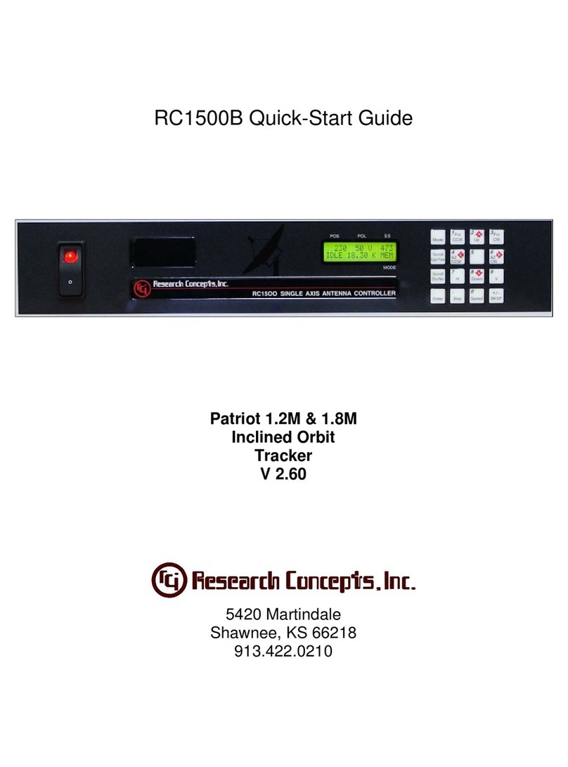
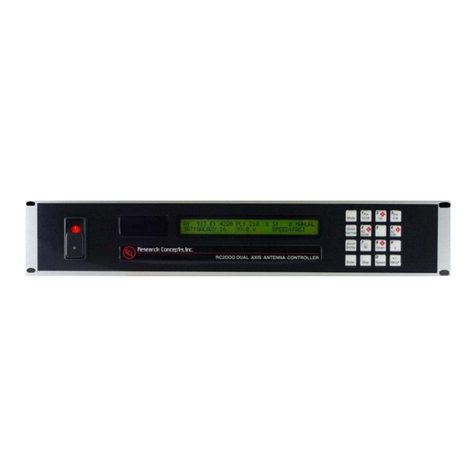
RESEARCH CONCEPTS RC1500B User manual

RC1500 Antenna Controller Implementation
The RC1500 is derived from the RC2000C Polar dual axis antenna controller. The RC2000C
Polar controller tracks inclined orbit satellites with a polar mount that provides for either a
motorized declination or motorized latitude angle adjustment. The feed wiggler system is similar
to the variable declination polar mount.
The RC1500 product is currently ‘hosted’ on an RC2000. The back panel of the RC1500 is
labelled identically to an RC2000. On the ‘1500, use the azimuth motor drive and sense lines to
interface to the antenna actuator.
LCD Display
The RC1500 employs a 16 column by 2 row display. The RC2000 employs a 2 x 40 LCD. The
screens of the RC2000 were shrunk to form the RC1500’s display. On the RC1500 the
controller’s current operating mode is displayed in a three character field in the lower right hand
corner of the display. Here are the three character mode designations…
MAN – Manual mode, AUT – Auto mode, SET – Setup mode, FIX – Fix or Resync mode, REM
– Remote mode, RST – Reset mode, CFG - Configuration, LIM – Limit mode, STP – Track
mode Step Track sub-mode, SEA – Track mode Search sub-mode, MEM – Track mode Program
(or Memory) sub-mode, MNU – Track mode Menu Sub-mode, ERR – Track Mode Error sub-
mode.
Tracking Algorithms
The tracking algorithms of the RC1500 have been simplified relative to those of the RC2000.
Step Tracking - On the 1500 two CONFIG mode items control the performance of the tracker.
The Step Size CONFIG mode item specifies the step size (in actuator position counts) that the
controller takes. The Pk Interval CONFIG item controls the time between peaking operations (in
seconds).
Automatic Search – The limits of the search will be from the (down_limit + 10 cnts) to the
(up_limit – 10 cnts).
Program (or Memory) Track – When memory tracking, the controller will reposition the antenna
whenever the difference between the actual antenna position and the antenna position derived
from the track table differ by (Step Size / 2) or more. Step Size refers to the CONFIG mode
item.
Track Menu – Whenever track mode is active and the time is displayed on the bottom line of the
display the user can hit the 0 key to invoke the track mode menu.

Setup Mode
In SETUP mode, for inclined orbits satellites, the controller will prompt for satellite lat/lon and
inclination. These values are not used by the tracking algorithms and these prompts will be
removed in a future revision of the software.
PC Remote Control
The controller’s REMOTE mode has not been tested. The software was modified to support
remote operation. The comm protocol of the RC1500 is nearly identical to that of the RC2000.
With the 1500, for the Query Status command, antenna position and status are reported in the
RC2000’s azimuth fields. The elevation fields in the reply have been blanked out.
For the Auto Move to Target Position command the antenna position should be reported in the
azimuth field.
For the Miscellaneous - Reset Axis command, to remotely reset a drive fault either the ‘A’ or ‘E’
sub parameter will reset the drive.

Single Axis Tracking with the RC1500B
The apparent motion of an inclined orbit satellite appears as a narrow figure 8 pattern aligned
perpendicular to the geo-stationary satellite arc. As the inclination of the satellite increases both
the height and the width of the figure 8 pattern increase. The single axis tracker can follow the
long dimension of the figure 8 but cannot compensate for the width of the figure 8 pattern. A
paper (available on our web site - http://www.researchconcepts.com/Files/track_wp.pdf)
describes the height and width of the figure 8
pattern as a function of the inclination of the
satellite’s orbit.
Note that the inclination of the satellite
increases with time. The maximum rate of
increase is approximately 0.9 degrees per
year. As the inclination increases, the width
of the figure 8 pattern will also increase. This
has two implications for system performance.
One, the maximum signal loss due to antenna
misalignment will increase with time, and
two, the antenna must have range a of motion
sufficient to accommodate the greatest satellite inclination that will be encountered.
Many people feel that single axis tracking is viable for antenna’s up to 3.8 meters at C band and
2.4 meters at Ku band. Implicit in this is the fact that the inclination of most commercial
satellites is not allowed to exceed 5 degrees. This assumption should be verified before a system
is fielded.
A single axis tracking system must be in precise mechanical alignment to minimize loss due to
the mount’s inability to compensate for the width of the figure eight pattern. For this reason, a
single axis tracker is more difficult to setup than other inclined orbit satellite tracking mounts.
Conversely, the operation of a single axis tracking antenna is more straightforward than that of
dual axis antennas. The satellite will always be located somewhere within the antenna’s range of
travel so there is no danger of peaking up on an adjacent satellite. The controller can be operated
with the search feature enabled – even for transmit applications.
Control Axis Tilt for a Single Axis Tracking Satellite Antenna
The control axis of the antenna should be rotated by an amount equal to…
-ATAN[ sin(delt_L) / tan(L) ]
where L is the earth station latitude and delt_L is the difference in longitude between the satellite
and the antenna. The sense of the angle is relative to an observer located behind the antenna
looking through the antenna at the satellite. Positive angles correspond to a clockwise deflection
from vertical, negative angles correspond to a counter-clockwise deflection from vertical. This

result was obtained from the publication Inclined Orbit Satellite Operation in the Intelsat System
written by Rory Chang and Les Veenstra, revised July 1991.
Many people make the mistake of plotting satellite azimuth vs. elevation and obtaining an
‘angle’ by looking at the ratio of azimuth to elevation movement. The problem with this
approach is that at elevation angles greater than zero, one degree of azimuth movement does not
change the antenna pointing angle by one degree. When antenna elevation angle is 90 degrees,
changing the antenna azimuth angle does not change the antenna pointing angle at all (it does
change the polarization, however).
RC1500.XLS Spreadsheet
A spreadsheet has been developed that performs a number of calculations related to single axis
tracking.
The spreadsheet takes as its inputs…
1. Antenna operating frequency and diameter,
2. Satellite longitude and inclination. Inclination of the satellite’s orbital plane with respect to
the earth’s equatorial plane. This data can sometimes be obtained from www.lyngsat.com
(select a satellite, from the satellite page select Sat Tracker, a summary of satellite info is
given) or from a two line element (TLE) set – see ‘Setting Up a Single Axis Tracker’, step 1,
for the data format of a TLE set.
3. Earth station latitude/longitude
Given this information, the spreadsheet calculates the following quantities…
1. Antenna 3 dB beamwidth (in degrees),
2. Height and width of the figure eight pattern of the satellite’s apparent motion (the height and
width are the angular extent of the satellite’s motion in degrees),
3. The maximum signal loss (in dB) due the single axis tracker’s inability to compensate for the
width of the figure eight pattern.
4. The tilt of the control axis (in degrees)
The spreadsheet uses a parabolic function to characterize the relationship between antenna
angular misalignment and signal loss. The spreadsheet also calculates signal loss given antenna
pointing error and vice versa.
RC1500B Tracking Algorithms
The apparent motion of an inclined orbit satellite repeats itself every 23 hours, 56 minutes, and 4
seconds. The tracking scheme used in the RC1500B employs a step track algorithm to build up a
track table which logs the satellite position versus time ( a real time clock powered by a lithium

battery is present in the controller). If the current time corresponds to a portion of the satellite’s
apparent motion for which there are valid entries in the track table, the controller switches over
to a memory track algorithm. When the memory track algorithm is controlling antenna
movement, the antenna smoothly tracks the satellite based on linear interpolation of the position
data stored in the track table.
If the satellite transponder goes down while the controller is step tracking, the controller enters a
search mode. Two search modes are supported: manual and automatic. In the manual search
mode the user is prompted to manually position the antenna on the satellite and hit a key to
continue tracking. With the automatic search mode, the controller periodically scans the antenna
looking for signal strength. The user can select manual or automatic search via the controller’s
CONFIG mode.
For implementing the step track algorithm, the controller requires an analog voltage that varies
with received signal strength. The controller can accept voltages from 0 to 10 volts. The analog
voltage required for tracking can be obtained from a beacon receiver or from an AGC (automatic
gain control) or signal strength tuning meter output from an analog receiver or modem.
Setting Up a Single Axis Tracker
The following steps represent the ideal method to configure a single axis tracking system. In
practice, this method may not be practical because it requires that the installer initially configure
the tracker and then return to the site to readjust the mount. This procedure also assumes that the
antenna pointing angle and control axis tilt can be set independently.
1. Obtain ephemeris data on the satellite. This provides the azimuth bearing and elevation
angle to the satellite as a function of time.
Two common methods are employed to obtain satellite ephemeris. One employs the SDP4
algorithm using Two Line Element (TLE) parameters compiled by NORAD (North
American Air Defense) Command. See www.celestrak.com for a program that implements
the SDP4 algorithm and TLE data sets.
The other method is to use the IESS-412 software and parameters available from Intelsat
(www.intelsat.com). IESS-412 data is generally only available for Intelsat satellites. An
SDP4 program is also available from Research Concepts, Inc. Contact
Note that the third data field on the second line of a two-line element data set entry is the
inclination of the satellite’s orbital plane with respect to the earth’s equatorial plane. The
first data field on the second line of a two-line element set always contains ‘2’.
2. Use a geostationary satellite antenna pointing solution calculator to determine the satellite’s
nominal azimuth and elevation pointing solution. Nominal position here refers to what the
az/el position of the satellite would be if it were geostationary. An antenna pointing
calculator (such as ANTENNA.EXE, available for download at
http://www.researchconcepts.com/antenna.htm) can provide this information given the
latitude/longitude of the earth station and the longitude of the satellite.

3. With the nominal satellite azimuth and elevation angles and the ephemeris data, determine
the time at which the satellite will be at the nominal position (sometimes also called ‘center
of box’) and the times which the satellite will be at the top and bottom of the figure eight
pattern. The time that corresponds to center of box is when the az/el from ephemeris data
matches the nominal az/el angle.
4. Determine the control axis tilt for the single axis antenna. This quantity can be calculated
using the equation given above or the RC1500.XLS spreadsheet described earlier.
5. Position the antenna in the center of it’s range of travel. Adjust the control axis tilt angle to
the value calculated in step 4. Mechanically adjust to the antenna pointing angle to be the
nominal az/el position.
6. When the satellite is at the ‘center of box’, adjust the antenna pointing angle mechanically to
peak up the received signal strength. Do not adjust the control axis tilt.
7. When the satellite is at either endpoint of the figure eight pattern adjust the control axis tilt.
Research Concepts, Inc.
5420 Martindale Road
Shawnee, KS 66218-9680 USA
Phone: 913/422-0210 • Fax: 913/422-0211
www.researchconcepts.com

RC1500B Single Axis Tracking Antenna Controller Chapter 1 Introduction 1
Research Concepts, Inc.; 5420 Martindale; Shawnee, KS 66218 WWW.RESEARCHCONCEPTS.COM
Chapter 1 INTRODUCTION
The RC1500B antenna controller is designed to control an single axis, inclined orbit satellite
tracking antenna. The standard model is designed to interface to 36 volt actuators with pulse
type position sense feedback. Another version of the RC1500B is designed to interface to
motorized antenna feed translation systems. These controllers provide a 12 volt DC output to the
antenna actuator. These ‘Low Voltage’ output models can be identified by the ‘LV’ suffix in the
controllers model number designation on the serial number plate found on the back panel of the
controller.
Here is a brief listing of the capabilities of the RC1500B …
1. The controller utilizes a solid state drive system capable of providing 8 amps to the antenna
actuator. The drive system has built-in over-current sensing with mechanical relay backup to
disconnect the drive from the actuator in the event of a fault.
2. The controller can control polarization via a polarotor (or servo) type interface. The
AUTO_POL feature allows the polarization to be controlled via a digital input or contact
closure supplied by a receiver to the controller. An RC2KPOL option is available to provide
control for a Seavey type two or four port feed with potentiometer feedback. If no
polarization control device will be present in a given installation configure the controller for
the servo option by setting the 24 vdc Rot Feed CONFIG mode item to ‘0’.
3. Position sensing feedback can be supplied by any pulse based sensor - reed switch, Hall
effect, or electro-optical. There is no need for special sensors or actuators. The RC2000C
keeps track of both rising and falling pulse edges from the pulse sensor for increased
accuracy.
4. The RC1500B can maintain multiple tracks for a given satellite. In addition, a number of
fixed positions can be programmed into the controller’s memory.
5. The Adapti-Drive variable speed control system allows the user to specify the desired slow
speed for the fundemental axis. The Adapti-Drive system will then adjust the actuator
voltage (via a pulse width modulation scheme) to maintain the speed selected by the user.
This alleviates the problem of poor speed regulation with varying direction along a given axis
associated with constant voltage slow speed systems.
6. The RC1500 is equipped with an RS-422 communications port. This allows the controller to
interface with a PC. The communication protocol used is compatible with the popular SA-
Bus protocol. An optional RS-232 to RS-422 interface converter, designated RC1KADP, is
available to convert the RS-232 interface (which is standard on PC's) over to the RS-422
interface required for the SA-Bus protocol used on the RC1500.
7. The tracking scheme used in the RC1500B employs a step track algorithm to build up a track
table which logs the satellite position versus time ( a real time clock powered by a lithium
battery is present in the controller). If the current time corresponds to a time interval for
which there are valid entries in the track table, the controller switches over to a memory track
2RC1500B Single Axis Tracking Antenna Controller Chapter 1 Introduction
Research Concepts, Inc.; 5420 Martindale; Shawnee, KS 66218 WWW.RESEARCHCONCEPTS.COM
algorithm. In this mode the antenna smoothly tracks the satellite based on position data
stored in the track table.
If the satellite transponder goes down while the controller is step tracking, the controller
enters a search mode. Two search modes are supported: manual and automatic. In the
manual search mode the user is prompted to manually position the antenna on the satellite
and hit a key to continue tracking. With the automatic search mode, the controller
periodically scans the antenna looking for signal strength. The user can select manual or
automatic search via the controller’s CONFIG mode.
1.1 Organization of this Manual
This manual is divided into two broad parts, Installation and Reference. The Installation part of
this manual is designed to familiarize the user with the controller and guide him or her through
the installation and configuration of the controller. The Reference portion of the manual gives a
detailed description of all of the features and capabilities of the controller.
The Installation portion of the manual is comprised of Chapters 2 through 4. Chapter 2 explains
the user interface and the basic operation of the unit. Chapter 3 guides the user through the
physical installation and wiring of the unit as well as the initial software configuration. Chapter
4 covers all aspects of tracking inclined orbit satellites. It begins with a brief discussion of some
of the theoretical aspects of the inclined orbit, and continues with a description of the algorithms
used by the RC1500B for tracking inclined orbit satellites. Chapter 4 concludes with a step by
step procedure which guides the user through the entry of track parameters and the initialization
of a track on an inclined orbit satellite.
The Reference portion of this manual is comprised of chapters 5, 6, and 7 as well as the
appendices which follow. These chapters of the manual describe the fields on the screens which
the user will encounter, as well as the data which can be entered at any prompt. After the initial
installation, when the user has become familiar with the operation of the controller, these
chapters will probably be the only ones consulted by the user to handle the routine chores of
adding new satellites and deleting old ones.
1.2 Before You Begin
Please read and understand the manual. Time invested in understanding the installation and
operation of the controller will insure satisfactory results. The unit has been tested thoroughly
and will work accurately and reliably if it is installed and configured properly. There is an old
saying in the controller business - "Garbage in, garbage out".

RC1500B Single Axis Tracking Antenna Controller Chapter 2 Basic Function 3
Research Concepts, Inc.; 5420 Martindale; Shawnee, KS 66218 WWW.RESEARCHCONCEPTS.COM
Chapter 2 BASIC FUNCTION DESCRIPTION
This chapter describes the controller's front panel layout, user interface and basic operation.
When the user has completed this chapter, he or she should have a basic understanding of the
various operating modes of the unit, and be able to use the keyboard and liquid crystal display
(LCD) to navigate through those modes.
2.1 Front Panel
The front panel (figure 2.1) of the RC1500 contains an ON/OFF switch, a 2 row by 16 column
backlit LCD, and a 4 by 4 matrix keypad with tactile feedback. The controller’s back panel is
described in chapter 3.
Figure 2.1
The three character field in the lower right hand corner of the LCD is reserved for the display of
the current mode of the controller. The various modes are introduced in the following section. If
an error condition is active, an error message will periodically flash across the bottom row of the
display. Error messages are discussed in chapter 7. Chapter 5 explains the contents of every
field on the display for all of the various controller modes.
An examination of the keyboard in figure 2.2 reveals that many of the keys have 2 or more
labels. The function of each key is determined by the current operational mode of the controller.
The various modes are discussed in the following section.
Figure 2.2

4RC1500B Single Axis Tracking Antenna Controller Chapter 2 Basic Function
Research Concepts, Inc.; 5420 Martindale; Shawnee, KS 66218 WWW.RESEARCHCONCEPTS.COM
MODE
Toggling this key allows the user to set the desired mode of the controller. There are two
mode groups – operational and programming. See section 2.2 – Changing Modes with
the Mode Key. The MODE key is always active.
SCROLL UP/SCROLL DOWN
These keys are used to scroll up or down through a list of items.
YES/NO
These keys are used to supply an answer to a yes or no question.
ENTER
This key is used to select an entry from a list, terminate a prompt for some action by the
user, or to complete the entry of numeric data.
0-9/DECIMAL POINT (with the stop key)/BKSP/+/-
These keys are used for numeric entry. The BKSP key causes the cursor to move one
column to the left writing over the character which was there. During the entry of
numeric data, if the cursor is in the first position of the data entry field, hitting the +/- key
will toggle the sign of the numeric input.
SPEED
This key toggles the antenna speed from fast to slow and vice versa.
ARROW KEYS - 2/4/6/8
These keys are used to manually jog the antenna in some modes. The left and down
arrow keys jog the antenna one direction while the right and up arrow keys jog the
antenna in the other direction.
CCW/CW/H/V
These keys control the Polarization. The CCW and CW keys skew the polarization
control device counterclockwise and clockwise. The H and V keys are used to either
select or specify the polarization position associated with a given satellite.
Note that all of these keys are not active simultaneously. The function of each key is dependent
on the current mode of the controller. In some modes certain keys are ignored.
2.2 Changing Modes with the MODE Key
The user can switch the current controller mode by use of the MODE key. The MODE key is
always active - when the MODE key is depressed and released, the controller's current mode will
change.
There are two mode groups – operational and programming.
Operational modes consist of MAN (manual mode), AUT (auto mode), REM (remote mode),
STP (track mode, step track sub-mode), SEA (track mode, search sub-mode), MEM (track mode,

RC1500B Single Axis Tracking Antenna Controller Chapter 2 Basic Function 5
Research Concepts, Inc.; 5420 Martindale; Shawnee, KS 66218 WWW.RESEARCHCONCEPTS.COM
memory track sub-mode), MNU (track mode, menu sub-mode), ERR (track mode, error sub-
mode).
Programming modes consist of SET (setup mode), LIM (limits), CFG (config), DEL (delete),
FIX (resync mode), RST (reset mode).
The Operational modes are the ones used in everyday operation of the controller.
To switch between modes in a group, press the MODE key and release. The new mode will
display in the upper right hand corner of the display. To switch to the other group of modes,
hold the MODE key in for five seconds and release. This scheme was designed to help keep
inexperienced personnel from inadvertently changing any of the programmed parameters
specified during system setup. It is also recommended that Expert Access be used to safeguard
the integrity of the data (see section 2.5).
2.3 Mode Descriptions
The mode system on the RC2000C antenna controller resembles the menu system used with
many personal computer (PC) programs. On a PC program a menu system allows the user to
perform operations or to enter in data. The user must navigate through the menu structure to the
particular menu which allows access to the function or data that the user wishes to manipulate.
On the RC2000C the mode which is currently active is always displayed in the upper right hand
corner of the LCD. Here is a summary of the modes implemented on the RC2000C.
MANUAL
1673 50 H 247
GALAXY 6 F
MAN
In manual mode you can:
1. Jog the antenna about the fundemental control axis using the ARROW KEYS
2. Toggle the speed from fast to slow (and vice versa) with the SPEED key.
3. Jog the polarization with the CCW/CW keys.
4. Use the H/V keys to toggle between the preset H and V polarizations of the satellite which
was the last target of an AUTO move.
When MANUAL mode is active the following information is displayed on the top row of the
LCD: antenna position, polarization position, polarization position code (H or V) and the current
signal strength. The signal strength is derived from a receiver or modem automatic gain control
(AGC) output or a dedicated beacon receiver.
The bottom row of the LCD displays the satellite name and the antenna speed (‘F’ for fast, ‘S’
for slow). While jogging the antenna at slow speed a symbol is displayed to the right of the ‘S’

6RC1500B Single Axis Tracking Antenna Controller Chapter 2 Basic Function
Research Concepts, Inc.; 5420 Martindale; Shawnee, KS 66218 WWW.RESEARCHCONCEPTS.COM
banner. The symbols displayed are … \, |, /, -, \, ., and + and a function of the voltage applied to
the drive.
The RC1500 employs a software servo system to maintain a constant slow speed. The user
specifies a slow speed via the Slow Speed CONFIG mode item. As the antenna moves at slow
speed the controller determines the antenna speed by measuring the time interval between
successive position pulses. The voltage applied to the drive is adjusted to maintain a constant
antenna speed. As the voltage applied to the drive increases the \, |, /, and – symbols appear to
rotate clockwise. Similarly, as the voltage ramps down the symbols appear to rotate counter-
clockwise. The . symbol is displayed when the minimum voltage is applied to the drive and the
+ symbol is displayed when the maximum voltage is applied to the drive.
AUTO
SELECT SAT
GALAXY 6
AUT
This mode allows the user to automatically position the antenna on any satellite that has been
programmed into memory via SETUP mode. The list of programmed satellites is reviewed via
the SCROLL UP/DOWN keys, and the ENTER key initiates the automatic move. The STOP
key will terminate the move. When the antenna is positioned, the controller will switch to
MANUAL mode for a geostationary satellite, and track mode is activated for an inclined orbit
satellite.
REMOTE
1673 50 H 247
GALAXY 6 F
REM
In this mode the controller receives and acts on commands received via the communications
port. This mode can only receive control if enabled via the Remote Enable CONFIG mode item.
The only key which is active is the MODE key, which can be used to switch to a different mode.
SETUP
761 74 H 132
TELSTAR302 F
SET
This mode allows the user to store satellite position and horizontal/vertical polarization values
into the controller's non-volatile memory. Once stored in memory, the satellite is available for
recall by AUTO mode.

RC1500B Single Axis Tracking Antenna Controller Chapter 2 Basic Function 7
Research Concepts, Inc.; 5420 Martindale; Shawnee, KS 66218 WWW.RESEARCHCONCEPTS.COM
When SETUP mode is invoked …
1. the user peaks the antenna up on the desired satellite
2. the SCROLL keys are used to scroll through a list of satellite names stored in the controller's
EPROM memory. When the desired name is found,
3. the ENTER key assigns it to the current position and polarization. (If the user wishes to
assign a name which is not stored in the satellite's EPROM memory, the USER can manually
enter the name. See page 56.)
The user is then prompted to specify the H and V polarization values for the satellite. If the
antenna does not employ motorized polarization adjustment the user must still specify the H and
V polarization values to the controller. For this case, the 24 vdc Rot Feed CONFIG mode item
should be set to No to indicate to the controller that a 3 wire servo type polarization control
system is present. A servo polarization device does not provide feedback to the controller.
When the controller is configured for servo based polarization control, when specifying the
satellite horizontal and vertical polarization positions at the H and V prompts make sure that the
polarization position is not at the CW or CCW limit.
When the user has entered in all of the requested data, the controller will respond with "DATA
ACCEPTED", and the user can jog the antenna to another satellite and repeat the procedure. If
the satellite just entered was an inclined orbit satellite, the controller will transfer control to
TRACK mode to initiate tracking on the satellite.
RESET
JAMMED OK
A/E-1,2-PL:_ RST
This mode allows the user to examine the error status of the motor drive circuits and reset them if
a fault has occurred. The drive systems of each axis are independent. The status of the antenna
drive is displayed on the top line below the ‘POS’ banner and the status of the polarization drive
is displayed below the ‘POL’ banner. Polarization errors will only be shown if a rotating feed is
present (the 24 vdc Rot Feed CONFIG mode item is set to Yes).
A DRIVE error indicates that the drive circuits detected an over current fault and shut down. A
JAMMED error indicates that the antenna actuators were commanded to move but no movement
was detected. A RUNAWAY error indicates that antenna movement was detected when the
actuators were not energized. A SENSOR error indicates backwards movement of the pot. Any
antenna drive error condition can be reset by pressing the key designated on the bottom line of
the display. Errors are covered in chapter 6.
DELETE
SELECT
SATELLITE

8RC1500B Single Axis Tracking Antenna Controller Chapter 2 Basic Function
Research Concepts, Inc.; 5420 Martindale; Shawnee, KS 66218 WWW.RESEARCHCONCEPTS.COM
GALAXY 6
DEL
This mode allows the user to delete satellites from non-volatile memory. The SCROLL
UP/DOWN and ENTER keys are active.
RE-SYNC
SELECT
SATELLITE
GALAXY 6 FIX
The antenna azimuth and/or elevation position can be corrupted by any number of causes (sensor
failure, lightning strike, faulty shield connection, etc). If there is an error in the position counts,
the controller cannot properly position itself on the satellites stored in non-volatile memory, and
the limits are not valid. In this situation, it is necessary to re-synchronize the controller's internal
position counts.
To do this, the operator positions the antenna on a known satellite which has previously been
stored in the controller's non-volatile memory (preferably a Ku band satellite, since the
beamwidth of the antenna is narrower at Ku band than at C band). The user then activates RE-
SYNC mode, and uses the SCROLL UP/DOWN keys to select the satellite name with which the
antenna is currently aligned. When the ENTER key is hit, the controller's internal position
counts for that satellite are initialized to the current position, and a corresponding adjustment is
made to all other satellite positions across the arc.
CONFIG
AUTOPOL
ENABLE:*
0-NO, 1-yes CFG
This mode allows the user to view and enter configuration data into the controller. This data is
stored in non-volatile memory and is used to set certain parameters and enable or disable certain
controller options. The following parameters and options are controlled or configured via data
entered into the controller from CONFIG mode:
AUTOPOL
Remote communication port parameters
time and date
elevation zero position
slow speed control parameter
polarization options
drive systems options
tracking system parameters
In CONFIG mode, the SCROLL UP/DOWN keys are used to select the parameter to be viewed
or modified. Asterisks in data entry field implies that the present value of the CONFIG item is
invalid. The CONFIG mode item can be modified using the numeric keypad to key in a new
value. For the value to be accepted the entry must be terminated by the hitting ENTER key. The

RC1500B Single Axis Tracking Antenna Controller Chapter 2 Basic Function 9
Research Concepts, Inc.; 5420 Martindale; Shawnee, KS 66218 WWW.RESEARCHCONCEPTS.COM
prompt message on the bottom row of the display provides data entry instructions. For some
CONFIG mode items, one of the two possible data values lower case text. For these items the
upper case prompt specifies the default value of the parameter.
LIMITS
705 24 431
7-SET CCW/DN
LIM
This mode allows the user to set the antenna’s logical limits. To set a logical limit the user jogs
the antenna to the position of the desired limit and hits the 7 key. The azimuth CCW or elevation
DOWN limits are set first. After this limit is set the user is prompted to set the azimuth CW or
elevation UP limit. Once the limits are set the antenna cannot be moved (except in LIMITS
mode) to a position that is not within the logical limits. In LIMITS mode the controller will not
detect an antenna jammed condition. When the first limit is set the antenna position is initialized
to 30.
TRACK
567 56 H 668
PEAKING STP
TRACK mode is activated to track an inclined orbit satellite. TRACK mode is slightly different
than the other modes described above in that TRACK mode cannot be reached directly through
the use of the MODE key. TRACK mode can be entered only via the SETUP or AUTO modes.
When TRACK mode is active the track sub-mode is displayed in the lower right hand corner of
the display. The TRACK sub-modes are step track (STP), search (SEA), memory track (MEM),
menu (MNU), and error (ERR). TRACK mode is described in Chapters 4 and 5.
More detailed information is available concerning each of the modes described above in Chapter
5 of this manual.
2.4 Mode Access
Access to some modes is restricted in some circumstances. Here are the conditions which can
restrict access to certain modes:
1. TRACK mode can only be entered via the AUTO or SETUP modes - it cannot be entered via
the MODE key. When TRACK mode is active it is treated as if it were in the operational
mode group. If TRACK mode is active and the user presses the MODE key, control will
transfer to the MANUAL mode. If TRACK mode is active and the user holds the MODE
key in for five seconds and releases, control will transfer to SETUP mode.
2. REMOTE mode is only accessible when the Remote Mode Enable CONFIG mode item is set
to 1. When enabled, REMOTE mode can be activated either via the MODE key or by the
receipt of a command on the serial port. Note that most commands received via the serial
port may be processed while TRACK mode is active.

10 RC1500B Single Axis Tracking Antenna Controller Chapter 2 Basic Function
Research Concepts, Inc.; 5420 Martindale; Shawnee, KS 66218 WWW.RESEARCHCONCEPTS.COM
3. The expert access system can restrict access to certain modes. The intent is to avoid
corruption of the operating parameters by inexperienced personnel. The expert access
system is described in the next section.
2.5 Expert Access
An Expert Access flag is maintained by the controller. The user can inspect and change the state
of this flag via the CONFIG mode Expert On CONFIG mode item. When the flag is set (1) the
user has access to all controller modes (subject to the state of the Remote Enable CONFIG mode
item). When the Expert Access flag is reset (0), the user only has access to the MANUAL,
AUTO, REMOTE, RESET, and CONFIG modes.
The Expert Access flag also controls access to CONFIG mode items. When the flag is reset (0),
the user only has access to the Autopol Enable, Remote Enable, and Expert Access CONFIG
mode items. The user can toggle the state of the Expert Access flag by entering a 5 digit code at
the CONFIG mode Expert On CONFIG item. This 5 digit code is contained in a removable
appendix B at the end of this manual, to safeguard from any accidental corruption of operating
parameters by inexperienced personnel. Note that the Expert Access flag is set whenever the
controller's memory is cleared via the Reset Sys CONFIG mode item.
2.6 AutoPol
The AutoPol feature slaves the RC1500’s polarization control to an output derived from a
satellite receiver. The RC1500 has an AutoPol input accessible via connector J1 on the back of
the unit. When the controller is operating in MANUAL or REMOTE modes, this input is
monitored and the polarotor is controlled according to a digital level present at this input.
To configure the controller for AutoPol operation, the user must have:
1. a suitable output available on the satellite receiver which is connected properly to the
AutoPol input of the RC1500,
2. the polarity of the AutoPol input must be specified (Autopol Level CONFIG mode item), and
3. the AutoPol feature must be enabled (Autopol Enable CONFIG mode item).
When the polarity of the AutoPol input is specified, the user is informing the controller that a
given AutoPol input level (high or low) corresponds to vertical polarization. Configuring the
AutoPol system during installation is covered in more detail in chapter 3, and the CONFIG mode
prompts which enable and specify the polarity of the AutoPol input are described in Chapter 5 in
the CONFIG mode section.

RC1500B Single Axis Tracking Antenna Controller Chapter 3 Installation/Setup 11
Research Concepts, Inc.; 5420 Martindale; Shawnee, KS 66218 WWW.RESEARCHCONCEPTS.COM
Chapter 3 INSTALLATION/SETUP
This chapter guides the installer through the mechanical and electrical installation of the
controller as well as initial software setup.
This chapter describes the electrical connectors on the back panel of the controller, cabling
requirements, installation of optional polarization control devices, antenna limits, and
configuration of the antenna slow speed system.
3.1 Before You Begin
Before installing the unit the installer must ensure that the controller’s line voltage setting is
correct, the controller's memory has been cleared, and that he or she is familiar enough with the
mode system described in Chapter 2 to place the controller in any desired mode.
The RC1500 can be configured to operate on either 115 VAC or 230 VAC. The AC input
voltage the unit is currently configured for is displayed in a window located in the fuse holder
that is built into the IEC power entry module on the back panel of the controller. To change
the AC input voltage selection, remove the fuse holder and reverse the jumper assembly (on
which the ‘115’ and ‘230’ labels are located).
The fuse holder is designed to accommodate 1/4” by 1 1/4” fuses. If the RC1500 is configured
for 115 VAC operation, use a 5 amp slow blow (type 326) fuse. If the RC1500 is configured
for 230 VAC operation, use a 3 amp slow blow (type 326) fuse. For low voltage models
(identified by the LV suffix on the serial number plate found on the controller’s back panel) a 3
amp type 326 fuse should be used for 115 VAC installations and a 230 VAC fuse should be
used for 230 VAC installations.
When the AC line voltage has been verified, before the controller is interfaced to the antenna
the installer should become familiar with the controller's user interface. It is not necessary to
understand every aspect of the controller's operation to install the unit, but the installer should
be familiar with the mode structure of the RC1500 and be able to use the MODE key to place
the controller in any of the modes described in Chapter 2.
After the AC line voltage is verified and the user has become acquainted with controller’s user
interface the unit may be powered up. When the unit is powered up, it should be verified that
the controller goes to LIMITS mode ('LIM' displayed in the lower right hand corner of the
LCD). Before the controller is shipped from the factory, the memory is cleared and the
controller’s logical limits are invalidated. Whenever the unit is powered up and the limits are
invalid, the controller automatically places itself in LIMITS mode. Note that there may also be
a limits alarm message flashing on the bottom row of the display.
If the unit does not power up in LIMITS mode the installer should perform a system reset to
place the controller into a known state before proceeding with the installation.

12 RC1500B Single Axis Tracking Antenna Controller Chapter 3 Installation/Setup
Research Concepts, Inc.; 5420 Martindale; Shawnee, KS 66218 WWW.RESEARCHCONCEPTS.COM
To perform a system reset:
1. Use the MODE key to place the controller into CONFIG mode ('CFG' displayed in the
lower right hand corner of the LCD).
2. Use the SCROLL keys to bring up the Reset Sys screen. If the Reset Sys item does not
appear, the Expert Access flag (see section 2.5) may need to be reset.
To inspect the status of the Expert Access flag, use the SCROLL DOWN key (while still in
CONFIG mode) to bring up the Expert On CONFIG mode item. If a 1 does not appear in
the data entry field, enter the 5 digit code described in section 2.5 to toggle the Expert
Access flag on. This will allow access to the Reset Sys CONFIG mode item.
3. At the Reset Sys screen enter the same 5 digit code followed by the ENTER key.
3.2 Mechanical and Electrical Installation
Use 4 #10-32 mounting screws to secure the unit to a standard 19" rack. The controller’s back
panel is depicted in figure 3.1.
The back panel contains…
1) An IEC AC voltage input module with built-in fuse and line voltage select. Fusing
requirements and line voltage selection is described in section 3.1.
2) A removable, clamp style, 11 position connector (designated J1) that interfaces to …
a) the antenna actuator position sense lines (antenna position sense connections are
described later in this section),
b) the analog receiver, modem or beacon receiver analog output voltage that is proportional
to antenna received signal strength (interface described in section 4.x),
c) the Autopol input (section 3.8),
d) and the Polarotor 3 wire servo polarization control device (section 3.3). Please refer to
section 3.3 even if your system does not support polarization control.
Terminal 1 of connector J1 is labeled.
3) A removable, clamp style, 6 position connector (designated J2) to interface to the antenna
drive motor. The antenna actuator interface is described in this section. Terminal 1 of
connector J2 is labeled.
4) A DB-9 female connector (J3) for the SA-Bus compatible remote control interface.
Interfacing to the RC1500’s remote control connector is described in the appendices.

RC1500B Single Axis Tracking Antenna Controller Chapter 3 Installation/Setup 13
Research Concepts, Inc.; 5420 Martindale; Shawnee, KS 66218 WWW.RESEARCHCONCEPTS.COM
5) Optional – A removable, clamp style, 5 position connector (designated J4) that interfaces to
a rotating feed powered by a DC motor that employs a potentiometer for position feedback.
This connector will only be present if the RC2KPOL option is installed in the controller.
The RC2KPOL option is described in section 3.3. Terminal 1 of connector J4 is labeled.
6) Four potentiometers labeled AGC1 Gain, AGC1 Offset, AGC2 Gain, and AGC2 Offset.
The adjustment of these potentiometers is described in section 4.x.
7) A circuit breaker to protect the antenna drive (12 amps for a standard unit, 5 amps for a low
voltage model). When a circuit breaker of this type trips, it will protrude from its mounting
bezel. To reset a circuit breaker, turn the power switch off, wait a few minutes for the
circuit breaker to cool down, then depress the breaker so that it latches and is even with the
bezel.
3.2.1 Antenna Motor Drive
The antenna actuator motor drive is interfaced to the controller via the connector J2, terminals
4 and 6, labeled AZ1 and AZ2, respectively. In figures 3.2 and 3.3, these connections are to
the ‘Azimuth Motor’. Note that the RC1500 only supports a single axis antenna – the
terminals labeled EL1 and EL2 on J2 are not active.
The conductors that interface the controller to the antenna actuator must be sized appropriately
so that sufficient voltage is supplied to the motors. The voltage supplied to the motors will be
the output voltage from the controller less the voltage drop caused by the resistance of the
wires.
The output voltage of the controller is a function of the current supplied to the motors. The
voltage drop in the wires connecting the controller to the antenna is determined by the wire
size, the wire length, and the current supplied to the motors.
Low voltage versions of the controller typically interface to feed translation type antenna
actuators. These actuators draw low current and can be interfaced to the controller via 16
AWG conductors.
Figure A-1 in the back of this manual shows the relationship between the controller output
voltage and load current (for the standard 36 VDC output controller).
The following tables show the separation between the controller (36 VDC output model) and
the antenna which will result in 28 and 22 volts being applied to the antenna drive motors as a
function of motor current and wire gauge. The tables take into account the controller output
loading and resistive losses in the conductors.

14 RC1500B Single Axis Tracking Antenna Controller Chapter 3 Installation/Setup
Research Concepts, Inc.; 5420 Martindale; Shawnee, KS 66218 WWW.RESEARCHCONCEPTS.COM
Separation (in feet) between controller and antenna which will result in 28 volts being applied
to the motors:
Wire Size →
Motor Current ↓16 AWG 14 AWG 12 AWG 10 AWG
2 amps 600 950 1500 2410
3 amps 340 520 830 1350
4 amps 220 340 550 880
6 amps 90 140 230 340
8 amps 30 40 70 120
Separation (in feet) between controller and antenna which will result in 22 volts being applied
to the motors:
Wire Size →
Motor Current ↓16 AWG 14 AWG 12 AWG 10 AWG
2 amps 970 1530 2430 3930
3 amps 580 920 1460 2370
4 amps 400 640 1020 1650
6 amps 220 340 550 880
8 amps 120 190 310 500
A typical 36 volt actuator will draw 2 to 4 amps and will run at voltages down to about 12
volts.
3.2.2 Position Sense
Shielded cable with a bare drain wire MUST be used to minimize noise pickup. The
conductors that interface the controller to the sensor is often incorporated into a cable that
includes the motor drive conductors. If discreet sensor cable is required, Belden 8772
(consisting of three 20 AWG conductors enclosed in a foil shield with a bare drain wire) can be
employed.
Position count errors resulting from improper shielding is the most frequent problem that
occurs during the installation of the RC1500. Please observe the following precautions …
1. A shielded cable equipped with a bare drain wire must be used to interface the controller to
the position sensor.
2. The drain wire that provides an electrical connection to the shield must be connected to the
J1-6 terminal labeled Sensor AZ -. The Sensor AZ – terminal is at ground potential. The
shield must not be allowed to come in contact with earth potential at any other location.
3. At the sensor the shield must be left open. A short piece of heat shrink tubing can be
employed to insulate an frayed foil shielding from any metal objects at the sensor. If the
shield is allowed to come in contact with earth ground at the antenna ground currents could
flow in the shield which could induce noise in the sensor input circuitry.
Table of contents
Other RESEARCH CONCEPTS Controllers manuals

RESEARCH CONCEPTS
RESEARCH CONCEPTS RC2000A DUAL AXIS User manual

RESEARCH CONCEPTS
RESEARCH CONCEPTS RC1500 User manual

RESEARCH CONCEPTS
RESEARCH CONCEPTS RC3000 User manual

RESEARCH CONCEPTS
RESEARCH CONCEPTS RC2000C User manual

RESEARCH CONCEPTS
RESEARCH CONCEPTS RC2000C User manual

RESEARCH CONCEPTS
RESEARCH CONCEPTS RC3050 User manual

RESEARCH CONCEPTS
RESEARCH CONCEPTS RC4000 User manual

RESEARCH CONCEPTS
RESEARCH CONCEPTS RC4080 Use and care manual

RESEARCH CONCEPTS
RESEARCH CONCEPTS RC4500 Use and care manual

RESEARCH CONCEPTS
RESEARCH CONCEPTS RC4000 User manual