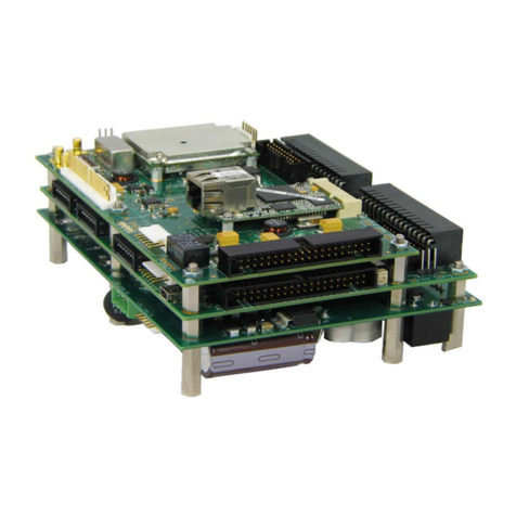
RESEARCH CONCEPTS RC4500 Use and care manual


RC4500 ACU
i
Revision History
DATE
MODIFICATION
SW VERSION
INITIALS
18 AUG 2016
Initial release.
2.03
JDK
05 OCT 2016
Corrections made to many screenshots and
descriptions. Reorganized chapters. The installation
procedure is now separated from the trouble-shooting
section.
2.03
JDK
10 NOV 2016
Updated warranty section.
N/A
BK
03 JAN 2017
Added detailed descriptions of signals for J6 –
Auxiliary I/O and J7 –Antenna I/O connectors.
2.03
JDK
02 AUG 2017
Massive review of content. Added embedded ACU
hardware section.
2.03
ECG
03 AUG 2017
Fixed section numbering and references.
2.03
ECG
09 JAN 2019
Updated to clarify how raw resolver angles are
calculated.
3.01
ECG
10 JAN 2019
Updated alarm descriptions.
3.01
ECG
26 MAR 2019
Updated limit determination procedures including
azimuth change from resolver to true.
3.01
ECG
02 MAR 2021
Update for software v3.10 release
3.10
TJB
22 DEC 2021
Added motor speed calibration and axis pointing
calibration
3.11
RLE

RC4500 ACU
ii
Limited Warranty
New Products
Research Concepts, Inc., RCI, warrants to the original purchaser this product shall be free from defects in
material and workmanship for one year, unless expressed otherwise, from the date of the original
purchase. During the warranty period, RCI will provide, free of charge, both parts and labor necessary to
correct such defects.
To obtain such a warranty service, the original purchaser must:
1. Notify RCI as soon as possible after discovery of a possible defect, with:
a. Model and serial number
b. Purchase date
c. Detailed description of the problem and circumstances when problem appears, including
details on the electrical connection to associated equipment
2. Obtain an RMA number from RCI, then ship the product to RCI in original packaging or its
equivalent, fully insured and shipping/customs charges prepaid. RCI is not responsible for
damage during shipping.
Repaired Products
RCI warrants repairs to be free from defects in material and workmanship for six months from the repair
date. If a possible defect is found, use the same process as above to obtain service.
Repair fees for end users are a flat charge based on the equipment being repaired.
Repair fees for Dealers and OEMs are an hourly labor charge plus parts cost. ** Dealers and OEMs are
responsible for receiving and shipping the products from their customer. **
___
RCI will pay for domestic shipping to return the product using the same method that RCI received it.
Customers are responsible for all international shipping charges.
Correct maintenance, repair, and use are important to obtain proper performance from this product.
Therefore, read the instruction manual carefully and completely. This warranty does not apply to any
defect that RCI determines is due to, but not limited to:
1. Improper maintenance or repair, including the installation of parts or accessories that do not
conform to the quality and specifications of the original parts
2. Misuse, abuse, neglect, or improper installation including disregard for installation of backup or
safety override equipment
3. Accidental or intentional damage, including lightning
4. Water / Liquid damage
There are no implied warranties.
The foregoing constitutes RCI’s entire obligation with respect to this product, and the original purchaser
and any user or owner shall have no other remedy and no claim for incidental or consequential damages.
For service: +1 (913)422-0210 support @researchconcepts.com

RC4500 ACU
iii
Table of Contents
1INTRODUCTION ...................................................................................................................................1
1.1 Manual Organization ......................................................................................................................1
1.2 Manual Conventions.......................................................................................................................2
1.3 RC4500 Features ...........................................................................................................................3
1.4 Hardware Overview........................................................................................................................4
1.5 Software Overview..........................................................................................................................5
1.5.1 Front Panel Overview..............................................................................................................5
1.5.1.1 Operational Group Functions........................................................................................5
Manual..........................................................................................................................5
Automatic Recall...........................................................................................................5
Automatic Move To.......................................................................................................5
1.5.1.2 Programming Group Functions.....................................................................................6
Configuration Screens..................................................................................................6
Maintenance Screens...................................................................................................6
1.5.2 Graphical User Interface Overview .........................................................................................7
1.6 Specifications..................................................................................................................................8
2SOFTWARE...........................................................................................................................................9
2.1 Operation Overview........................................................................................................................9
2.1.1 Front Panel Software Operation............................................................................................10
2.1.1.1 Front Panel Software Overview ..................................................................................10
Modes.........................................................................................................................10
Keypad Usage............................................................................................................11
Data Entry...................................................................................................................14
Display Layout............................................................................................................15
2.1.1.2 Front Panel Operating Group......................................................................................16
MANUAL Mode...........................................................................................................16
MENU Mode...............................................................................................................18
2.1.1.2.2.1 SETUP.................................................................................................................18
2.1.1.2.2.1.1 Beacon SETUP.............................................................................................20
2.1.1.2.2.1.2 AZ/EL Positioning..........................................................................................21
2.1.1.2.2.2 RECALL...............................................................................................................22
2.1.1.2.2.3 DELETE...............................................................................................................23
2.1.1.2.2.4 MOVETO .............................................................................................................24
2.1.1.2.2.5 DRIVE..................................................................................................................24
2.1.1.2.2.6 BEACON..............................................................................................................25
2.1.1.2.2.7 TRACK.................................................................................................................26
2.1.1.2.2.7.1 TRACK MENU...............................................................................................28
2.1.1.2.2.8 PEAKUP ..............................................................................................................29
2.1.1.3 Front Panel Programming Group................................................................................30
Configuration Mode ....................................................................................................30
2.1.1.3.1.1 Normal Access Items...........................................................................................32
2.1.1.3.1.1.1 Expert Access Permission ............................................................................32
2.1.1.3.1.1.2 Beacon Detection Points...............................................................................33
2.1.1.3.1.1.3 TLE 1 Data....................................................................................................34
2.1.1.3.1.1.4 TLE 2 Data....................................................................................................35
2.1.1.3.1.2 Install Access Items.............................................................................................36
2.1.1.3.1.2.1 Azimuth Calibration.......................................................................................36
2.1.1.3.1.2.2 Elevation Calibration .....................................................................................37
2.1.1.3.1.2.3 Polarization Calibration .................................................................................38
2.1.1.3.1.2.3.1 Multi-Feed Sensing Operation................................................................39

RC4500 ACU
iv
2.1.1.3.1.2.4 Feed Definition ..............................................................................................40
2.1.1.3.1.2.4.1 Multi-Feed Sensing Option.....................................................................40
2.1.1.3.1.2.5 External Sig Factors......................................................................................41
2.1.1.3.1.2.6 Beacon Sig Factors.......................................................................................42
2.1.1.3.1.2.7 RF Sig Factors ..............................................................................................43
2.1.1.3.1.2.8 Location Reset ..............................................................................................43
2.1.1.3.1.3 Super-User Access Items ....................................................................................44
2.1.1.3.1.3.1 System Definition ..........................................................................................44
2.1.1.3.1.3.2 Azimuth Angle Movement .............................................................................45
2.1.1.3.1.3.3 Azimuth Drive Parameters ............................................................................46
2.1.1.3.1.3.4 Elevation Angle Movement............................................................................47
2.1.1.3.1.3.5 Elevation Drive Parameters...........................................................................48
2.1.1.3.1.3.6 POL Angle Movement...................................................................................49
2.1.1.3.1.3.6.1 Multi-Feed Sensing Option.....................................................................49
2.1.1.3.1.3.7 POL Drive Parameters..................................................................................50
2.1.1.3.1.3.7.1 Multi-Feed Sensing Option.....................................................................50
2.1.1.3.1.3.8 Track Factors ................................................................................................51
2.1.1.3.1.3.9 Shake ............................................................................................................52
2.1.1.3.1.3.10 Location Reset ..............................................................................................53
2.1.1.3.1.3.11 Reset Defaults...............................................................................................53
Maintenance Items .....................................................................................................54
2.1.1.3.2.1 VOLTS .................................................................................................................54
2.1.1.3.2.1.1 10 Bit ADC Voltages......................................................................................54
2.1.1.3.2.1.2 12 Bit ADC Voltages......................................................................................55
2.1.1.3.2.2 DRIVE..................................................................................................................56
2.1.1.3.2.3 TIME.....................................................................................................................56
2.1.1.3.2.4 LIMITS..................................................................................................................58
2.1.1.3.2.5 COMMS ...............................................................................................................59
2.1.1.3.2.5.1 GPS Data ......................................................................................................59
2.1.1.3.2.6 MOVETO..............................................................................................................60
2.1.1.3.2.7 SHAKE.................................................................................................................61
2.1.1.3.2.8 BCN......................................................................................................................62
2.1.1.3.2.9 SNS OFF..............................................................................................................63
2.1.1.3.2.10 SYS INFO ............................................................................................................64
2.1.2 Graphical User Interface Software Overview........................................................................65
2.1.2.1 Graphical User Interface Main Page...........................................................................65
ACU Status Window...................................................................................................66
Antenna Position Display............................................................................................66
Local Jog Control........................................................................................................67
Main Display Window .................................................................................................68
2.1.2.1.4.1 Satellite Arc Display.............................................................................................68
2.1.2.1.4.2 Spectrum Analyzer Display..................................................................................69
2.1.2.1.4.2.1 Frequency Controls.......................................................................................70
2.1.2.1.4.2.2 Amplitude Controls........................................................................................70
2.1.2.1.4.2.3 Bandwidth Controls .......................................................................................70
2.1.2.1.4.2.4 Marker Controls.............................................................................................71
2.1.2.1.4.3 Tracking Diagnostic .............................................................................................71
Automatic Operations.................................................................................................73
2.1.2.1.5.1 Setup....................................................................................................................73
2.1.2.1.5.2 Recall...................................................................................................................73
2.1.2.1.5.3 Delete...................................................................................................................74
2.1.2.1.5.4 Peak Up ...............................................................................................................74

RC4500 ACU
v
2.1.2.1.5.5 Move To...............................................................................................................75
2.1.2.1.5.6 Drive Reset ............................................................Error! Bookmark not defined.
Signal Strength and Transmit Status..........................................................................76
Maintenance...............................................................................................................77
2.1.2.2 Configuration Page .....................................................................................................78
Satellite Database ......................................................................................................79
2.1.2.2.1.1 Satellite Configuration..........................................................................................80
System Configuration.................................................................................................81
2.1.2.2.2.1 ACU Configuration...............................................................................................81
2.1.2.2.2.2 GUI Configuration................................................................................................81
2.1.2.2.2.3 Additional IP Devices...........................................................................................82
Advanced....................................................................................................................83
2.1.2.2.3.1 Satellite Database................................................................................................83
2.1.2.2.3.2 Configuration Data...............................................................................................84
2.1.2.2.3.3 TLE Data..............................................................................................................85
2.1.2.2.3.4 ACU Firmware .....................................................................................................86
2.1.2.2.3.5 User Interface Firmware ......................................................................................87
3INSTALLATION ...................................................................................................................................89
3.1 Mechanical and Electrical Installation...........................................................................................89
3.1.1 Mechanical Mounting ............................................................................................................89
3.1.2 Electrical Interface.................................................................................................................90
3.1.2.1 J1-SENSORS..............................................................................................................91
3.1.2.2 J2-AGC........................................................................................................................92
3.1.2.3 J3-AZ RSLVR..............................................................................................................93
3.1.2.4 J4-EL RSLVR..............................................................................................................93
3.1.2.5 J5-PL RSLVR..............................................................................................................94
3.1.2.6 J6-ANTENNA AUX......................................................................................................95
3.1.2.7 J7-ANTENNA I/O ........................................................................................................96
3.1.2.8 J8-IP 1.........................................................................................................................99
3.1.2.9 J9-IP 2.........................................................................................................................99
3.1.2.10 J10-RF.........................................................................................................................99
3.1.2.11 J11-AC LINE ...............................................................................................................99
3.2 Software Initialization..................................................................................................................100
3.2.1 Motor Direction Calibration..................................................................................................101
3.2.1.1 Elevation Axis............................................................................................................101
3.2.1.2 Azimuth Axis..............................................................................................................101
3.2.1.3 Polarization Axis........................................................................................................101
3.2.2 Position Sense Direction.....................................................................................................102
3.2.2.1 Elevation Axis............................................................................................................102
3.2.2.2 Azimuth Axis..............................................................................................................102
3.2.2.3 Polarization Axis........................................................................................................102
3.2.3 Motor Speed Calibration......................................................................................................103
3.2.3.1 Elevation....................................................................................................................103
Fast Speed ...............................................................................................................103
Slow Speed ..............................................................................................................103
3.2.3.2 Azimuth .....................................................................................................................103
Fast Speed ...............................................................................................................103
Slow Speed ..............................................................................................................103
3.2.3.3 Polarization................................................................................................................103
3.2.4 Primary Position Sensor Calibration ...................................................................................104
3.2.4.1 Azimuth and Elevation Axis.......................................................................................104
3.2.4.2 Polarization Axis........................................................................................................105
RC4500 ACU
vi
Resolver or Optical Encoder.....................................................................................105
Potentiometer ...........................................................................................................105
3.2.5 Range of Travel and Limits Calibration...............................................................................107
3.2.5.1 Elevation Axis............................................................................................................107
Up Limit.....................................................................................................................107
Down Limit................................................................................................................107
3.2.5.2 Azimuth Axis..............................................................................................................108
CW Limit...................................................................................................................108
CCW Limit.................................................................................................................108
3.2.5.3 Polarization Axis........................................................................................................109
CW Limit...................................................................................................................109
CCW Limit.................................................................................................................109
3.2.6 Axis Pointing Calibration .....................................................................................................110
3.2.6.1 Elevation....................................................................................................................110
COAST .....................................................................................................................110
FAST/SLOW.............................................................................................................110
MAX ERROR............................................................................................................110
3.2.6.2 Azimuth......................................................................................................................111
COAST .....................................................................................................................111
FAST/SLOW.............................................................................................................111
MAX ERROR............................................................................................................111
3.2.6.3 Polarization................................................................................................................112
COAST .....................................................................................................................112
FAST/SLOW.............................................................................................................112
MAX ERROR............................................................................................................112
3.2.7 Locate Source Calibration...................................................................................................113
3.2.7.1 L-Band Power Detector.............................................................................................113
3.2.7.2 Beacon Tracking Receiver........................................................................................113
3.2.7.3 External Receiver......................................................................................................113
4SUPPORT..........................................................................................................................................114
4.1 Troubleshooting..........................................................................................................................114
4.1.1 Warning Displays.................................................................................................................114
4.1.1.1 General Warnings .....................................................................................................114
4.1.1.2 Azimuth......................................................................................................................114
4.1.1.3 Elevation....................................................................................................................114
4.1.1.4 Polarization................................................................................................................115
4.1.1.5 GPS...........................................................................................................................115
4.1.2 Alarm Displays.....................................................................................................................115
4.1.2.1 General Alarms .........................................................................................................115
4.1.2.2 Azimuth......................................................................................................................115
4.1.2.3 Elevation....................................................................................................................116
4.1.2.4 Polarization................................................................................................................117
4.2 ACU Topics.................................................................................................................................118
4.2.1 Polarization Control.............................................................................................................118
4.2.2 Drive System.......................................................................................................................118
4.2.3 Position Sensing and Limits ................................................................................................118
4.2.3.1 Jam, Runaway, and Drive Error Sensing..................................................................119
4.2.4 Timekeeping........................................................................................................................120

RC4500 ACU Chapter 1 Introduction
1
1 INTRODUCTION
The RC4500 Antenna Control Unit (ACU) consists of a set of proprietary PCBs and antenna specific drive
units.
PLEASE READ AND UNDERSTAND THE MANUAL. Due to the complexity of the functions performed
by the RC4500, time invested in understanding its installation and operation will be well spent.
1.1 Manual Organization
The RC4500 PCB set allows for ACU functionality to be packaged in varied configurations. Also, many
hardware and software options are available for use with the RC4500 architecture. This manual is
organized to:
1) Describe common hardware and software elements that will apply to all instances of the RC4500
2) Provide a structure to allow definition of elements unique to a specific use of the RC4500
Chapter 1 summarizes the contents of the manual and highlights the functionality and features of the
RC4500.
Chapter 2 describes the core software features of the RC4500.
Chapter 3 covers RC4500 common installation and calibration procedures, provides help for system
troubleshooting and discusses detailed operational topics referred to in the manual.
Appendix A supplies the expert access codes on a single page, which at management’s discretion, may
be removed to eliminate the possibility of inexperienced users inadvertently corrupting configuration data.
Appendix B, titled "MOUNT SPECIFIC DATA", details unique functions and values unique to a specific
antenna mount. This Appendix may not be supplied from RCI if the ACU is not preprogramed for a very
specific antenna mount.
Appendix C, titled "ENCLOSURE SPECIFIC DATA", details mechanical and electrical details on how the
RC4500 is packaged. This appendix may not be supplied from RCI if the board set is not packaged in an
RCI provided enclosure.
Separate appendices describe additional features of the RC4500. Example optional appendices that
could accompany the manual include:
APPENDIX A –EXPERT ACCESS CONTROL
APPENDIX REM –REMOTE CONTROL PROTOCOL
APPENDIX SECURITY –SNMP AND SECURITY FEATURES

RC4500 ACU Chapter 1 Introduction
2
1.2 Manual Conventions
Throughout the manual, representations of screens the user will see will be shown in the boxed format
that follows:
A
Z
:
1
7
6
.
5
5
B
C
N
:
-
6
8
.
0
M
A
N
U
A
L
E
L
:
4
6
.
4
4
S
A
T
:
P
L
:
1
8
.
7
8
S
P
D
:
F
A
S
T
U
T
C
<
M
O
D
E
>
M
E
N
U
<
0
-
9
>
J
O
G
A
N
T
E
N
N
A
1
4
:
2
5
:
4
7
The following table shows typical abbreviations used both on RC4500 screens and in the manual’s text.
ITEM
ABREVIATION(S)
True azimuth angle
AZ
Elevation angle to horizon
EL
Polarization Angle
PL
Clockwise
CW
Counter-Clockwise (Anti-Clockwise)
CCW
Down
DN
Latitude
LAT
Longitude
LON
Satellite
SAT
Global Positioning System
GPS
Liquid Crystal Display
LCD
Signal Strength
SS
Satellite longitudes are presented in degree/decimal degree (79.0 W) format since that is the standard
representation of satellite positions. Latitude and longitude of the mount are presented in degree/decimal
(38.9554N, 94.7543W) format.
When referring to an ACU mode of operation, that mode’s name will be capitalized – ex. RECALL.
Throughout the manual and software, the latitude, longitude and true heading of the antenna are
collectively referred to as the antenna’s “position”.
Movements of the antenna (as seen from behind the antenna, looking at the geo stationary arc of
satellites) are represented by graphing the azimuth and elevation axes as shown below.

RC4500 ACU Chapter 1 Introduction
3
1.3 RC4500 Features
The ACU performs its functions via digital and analog electronic equipment interfaced to the antenna’s
motor drive and position sensor systems. This equipment is controlled through embedded software
algorithms run by the ACU’s microcontroller.
The RC4500 ACU is designed to automate the operation of high-performance earth station antennas.
Features provided can include:
•Automatic azimuth and elevation pointing solution calculation
•GPS receiver for accurate time-based tracking
•Automatic tracking of inclined orbit satellites via multiple tracking modes
oStep Tracking
oEnhanced Predictive Tracking
oTwo-Line Element Tracking (TLE)
•Automatic polarization control of rotating feeds
•Battery backed-up non-volatile memory for storing satellite locations and configuration data
•Automatic repositioning to stored satellites
•Continuous monitoring of antenna drive status
•Support for multiple band satellite operations
•Multiple User Interface Options
o4x40 Character Display + 4x4 keypad
oEthernet (IP-based) remote control Options
▪Remote 4x40 Character Display + 4x4 keypad
▪Intuitive Graphical User Interface (GUI)
▪SNMP
▪UDP

RC4500 ACU Chapter 1 Introduction
4
1.4 Hardware Overview
The following figure is a block diagram showing the four major components of the RC4500 ACU and how
they interface with a typical antenna system.
Individual interfaces will be described in detail in section 3.1.2. NOTE: Appendix C “Enclosure Specific
Data” will describe how these interfaces are mechanized for a board set in an enclosure.

RC4500 ACU Chapter 1 Introduction
5
1.5 Software Overview
The RC4500 allows easy antenna control via its mode-based operation. Multiple user interface (local and
remote control) options exist. Section 2.1.1 highlights the software functions by showing data that would
be presented if a user interface utilizes the 4x4 keypad and 4x40 character display. Section 2.1.2
highlights the software functions by showing data that would be presented when using the graphical user
interface option. The screen displayed to the user is based on the current controller mode. Controller
modes are divided into two major groups: operational and programming. The operational modes provide
for the normal operation of the antenna. The programming group provides for initial configuration of the
controller and will typically not be used on a day-by-day basis. The following example highlights the basic
modes of operation provided by the RC4500.
1.5.1 Front Panel Overview
When using the physical font panel, or the remote front panel the screen displayed to the user is based
on the current controller mode. Controller modes are divided into two major groups: operational and
programming. The operational modes provide for the normal operation of the antenna. The
programming group provides for initial configuration of the controller and will typically not be used on a
day-by-day basis.
1.5.1.1 Operational Group Functions
Manual
In MANUAL mode the user may jog the antenna in Azimuth, Elevation and Polarization
A
Z
:
2
0
4
.
9
3
R
F
:
-
5
0
.
9
M
A
N
U
A
L
E
L
:
4
1
.
9
6
S
A
T
:
W
B
-
1
P
L
:
4
5
.
0
0
S
P
D
:
F
A
S
T
U
T
C
<
M
O
D
E
>
M
E
N
U
<
0
-
9
>
J
O
G
A
N
T
E
N
N
A
1
4
:
2
5
:
4
7
Automatic Recall
In RECALL mode, azimuth, elevation, and polarization pointing angles are generated from data stored in
SETUP mode. The user selects which satellite to recall from the stored satellite list.
R
E
C
A
L
L
#
N
A
M
E
L
O
N
I
N
C
L
B
A
N
D
T
R
K
T
B
L
1
W
B
-
1
1
1
1
.
1
W
0
K
A
S
/
E
0
%
<
S
C
R
>
T
H
R
U
L
I
S
T
<
E
N
T
E
R
>
S
E
L
E
C
T
<
M
O
D
E
>
E
X
I
T
Automatic Move To
From MOVETO mode, the user may ask for the antenna to be automatically moved to user specified or
calculated positions via the longitude.
A
Z
:
2
0
4
.
9
3
(
2
0
4
.
9
3
)
<
0
>
S
P
D
:
F
A
S
T
M
O
V
E
T
O
E
L
:
4
1
.
3
9
(
4
1
.
3
9
)
<
5
>
S
E
N
S
O
R
:
A
N
G
L
E
P
L
:
4
5
.
0
0
(
4
5
.
0
0
)
<
6
>
L
O
N
:
<
1
>
S
E
T
A
Z
<
2
>
S
E
T
E
L
<
3
>
S
E
T
P
O
L
<
4
>
S
T
A
R
T

RC4500 ACU Chapter 1 Introduction
6
1.5.1.2 Programming Group Functions
Configuration Screens
Configuration mode screens allow the user to customize and calibrate the operation of the ACU for use
with a particular antenna. Verifying the correct configuration items will ensure correct operation with a
particular antenna.
M
O
D
E
:
2
A
N
T
S
I
Z
E
:
4
2
0
C
O
N
F
I
G
-
S
Y
S
T
E
M
A
N
T
L
O
O
K
:
1
<
2
-
M
E
N
U
3
-
M
A
N
U
A
L
>
Maintenance Screens
Maintenance mode screens allow the user to monitor sensor inputs and perform periodic maintenance
actions such as setting time and resetting drive errors.
S
Y
S
T
E
M
:
1
2
/
2
5
/
1
8
1
3
:
2
8
:
5
0
T
I
M
E
D
I
S
P
L
A
Y
:
1
2
/
2
5
/
1
8
1
3
:
2
8
:
5
0
Z
O
N
E
:
U
T
C
G
P
S
U
T
C
:
1
2
/
2
5
/
1
8
1
3
:
2
8
:
5
0
O
F
F
S
E
T
:
0
1
-
D
A
T
E
/
T
I
M
E
2
-
Z
O
N
E
3
-
O
F
F
S
E
T
4
-
G
P
S
S
Y
N
C

RC4500 ACU Chapter 1 Introduction
7
1.5.2 Graphical User Interface Overview
The graphical user interface control option is available via the IP interface of the controller. It is designed
to provide all the functions available from the front panel operation in an easy-to-use interface. As well as
provide current information of the system.

RC4500 ACU Chapter 1 Introduction
8
1.6 Specifications
RC4500 BOARDSET
Physical
Size
6 1/16" x 7" x 3 3/4" (PCB Set) / Drive components system dependent
Weight
2.6 lbs. (PCB Set) / Drive components system dependent
Temperature (Operational)
-40 to +60 deg. C.
Temperature (Storage)
-40 to +70 deg C.
Humidity
10% to 95% non-condensing
Position Sense
Azimuth
16-Bit Resolver, 25-Bit Optical Encoder
Elevation
16-Bit Resolver, 25-Bit Optical Encoder
Polarization
16-Bit Resolver, 23-Bit Optical Encoder, Potentiometer
Limit Switch Inputs
EL Up/Down. AZ CW/CCW, POL CW/CCW, additional options available
Locate Mode
AZ/EL Pointing Accuracy
±0.01° or better (16-bit), ±0.002° or better (25-bit)
POL Pointing Accuracy
±0.01° or better (16-bit), ±0.002° or better (23-bit), 0.1° or better (pot)
Positive Satellite
Identification
Multiple Beacon Tracking Receiver Options, DVB-S2, Modem, and Spectrum
Analyzer.
External AGC
Support for external analog signal source and lock input
Track Mode
Antenna Size
0.4 –25.0 meters
Tracking Accuracy
0.1 to 3.0 dB selectable; antenna dependent
Maximum Inclination
20°, standard
Tracking Modes
Step-Tracking, Predictive Tracking, NORAD TLE tracking
The RC4500 can be delivered as a printed circuit boardset, a 2RU rackmount enclosure, or as an
embedded encpsure within an outdoor Antenna interface Unit (AIU).

RC4500 ACU Chapter 2 Software
9
2 SOFTWARE
2.1 Operation Overview
The RC4500 allows multiple options for mechanizing the user interface. These can be divided into 2
distinct groups.
The first are versions that utilize a 4x4 keypad and 4x40 character display. Operation using this method
will be described in section 2.1.1 and includes the following methods of control:
•Rackmount Front Panel
•Handheld Remote Front Panel
•IP based remote front panel
The second is an IP based graphical user interface (GUI) method of control. Operation using this method
will be described in section 2.1.2.

RC4500 ACU Chapter 2 Software
10
2.1.1 Front Panel Software Operation
2.1.1.1 Front Panel Software Overview
Modes
The functionality of the RC4500 is achieved by placing the controller in the desired mode of operation.
The diagram below shows the hierarchy of the RC4500’s modes. Each mode has a unique display
screen that presents the information applicable to that mode’s operation.
Transition between groups by holding down the MODE key for 5 seconds
OPERATING GROUP
PROGRAMMING GROUP
Transition between modes by pressing the
MODE key
Transition between modes by pressing the
MODE key
MANUAL Mode
MENU Mode
CONFIGURATION
MAINTENANCE
2.1.1.2.1
2.1.1.2.2
2.1.1.3.1
2.1.1.3.2
SETUP
EXPERT ACCESS
VOLTS
2.1.1.2.2.1
2.1.1.3.1.1.1
2.1.1.3.2.1
RECALL
to
DRIVE
2.1.1.2.2.2
2.1.1.3.2.2
DELETE
RESET DEFAULTS
TIME
2.1.1.2.2.3
2.1.1.3.1.3.10
2.1.1.3.2.3
MOVETO
LIMITS
2.1.1.2.2.4
2.1.1.3.2.4
DRIVE
COMMS
2.1.1.2.2.5
2.1.1.3.2.5
PEAK UP
MOVETO
2.1.1.2.2.8
2.1.1.3.2.6
SHAKE
2.1.1.3.2.7
BCN
2.1.1.3.2.8
SNS OFF
2.1.1.3.2.9
SYS INFO
2.1.1.3.2.10
After initial pairing of an ACU to an antenna, the programming modes will typically not be used. Section
2.1.1.2 will give further details on the operating modes and Section 2.1.1.3 will give further details on the
programming modes. The rest of section 2.1.1.1 introduces common elements of all modes.

RC4500 ACU Chapter 2 Software
11
Keypad Usage
The keypad provides a flexible method of controlling the functionality of the ACU. While each ACU mode
has different requirements for user input, the use of the keypad remains consistent throughout all modes.
The keypad provides for both specific actions and general data input. As an example, the <2/UP/N> key
initiates an antenna up movement while in MANUAL mode but also allows for the entry of the number 2
when numeric entry is required or the indication of North when entering a latitude value. The required key
usage is provided in the detailed description of each mode.
The table on the following page describes both the specific action and general data entry function of each
key.

RC4500 ACU Chapter 2 Software
12
KEY LABEL
SPECIFIC FUNCTION
GENERAL FUNCTION
Mode
No specific function
Momentary push switches between modes within
group.
Button held for 5 seconds switches between
operational and programming groups.
Momentary push also exits sub-mode screens.
Scroll Up
Angle/CT
Toggles between multiple az/el
position display options in
Manual Mode
Scrolls forward through lists.
Provides “YES” answer to prompts.
Scroll Dn
RF/SS
Toggles between displayed
signal strength sources in
Manual Mode
Scrolls backward through lists.
Provides “NO”answer to prompts.
Enter
Heading Fix in Manual Mode
Complete entry of data.
Select entry from list.
Access sub-mode in CONFIG mode.
1
Pol CCW
Jogs polarization motor counter-
clockwise when pol movement is
allowed
Supplies “1”for numeric entry.
Use to select option 1 from a numbered list.
2 N
El UP
Jogs elevation axis up when in
MANUAL mode
Supplies “2”for numeric entry.
Supplies NORTH for latitude entry (12°34N).
Scrolls up during alphanumeric entries.
3
Pol CW
Jogs polarization motor
clockwise when pol is movement
allowed
Supplies “3”for numeric entry.
4 E
Az CCW
Move azimuth axis counter-
clockwise in MANUAL mode
Supplies “4”for numeric entry.
Supplies East for longitude entry (12345E).
5
H/V
Commands Cross-Polarization
movement in MANUAL mode,
Store
Supplies “5”for numeric entry.
Other manuals for RC4500
1
Table of contents
Other RESEARCH CONCEPTS Controllers manuals

RESEARCH CONCEPTS
RESEARCH CONCEPTS RC4500 User manual

RESEARCH CONCEPTS
RESEARCH CONCEPTS RC4080 Use and care manual

RESEARCH CONCEPTS
RESEARCH CONCEPTS RC4000 User manual

RESEARCH CONCEPTS
RESEARCH CONCEPTS RC2000A DUAL AXIS User manual

RESEARCH CONCEPTS
RESEARCH CONCEPTS RC1500 User manual

RESEARCH CONCEPTS
RESEARCH CONCEPTS RC3000 User manual

RESEARCH CONCEPTS
RESEARCH CONCEPTS RC2000C User manual

RESEARCH CONCEPTS
RESEARCH CONCEPTS RC2000C User manual

RESEARCH CONCEPTS
RESEARCH CONCEPTS RC1500B User manual

RESEARCH CONCEPTS
RESEARCH CONCEPTS RC3050 User manual