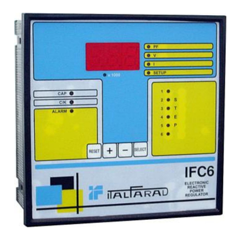
ITALFARAD IFC5 User manual

ITALFARAD S.p.A. via IV novembre n.1 Minerbio (BO) Italy
Istruzioni per l’uso
Operating instructions
Bedienungsanleintung
Notice d’utilisation
Instrucciones de uso
I
GB
D
F
E
Reactive Power Controller IFC5
I
GB
D
F
E

2
ITALFARAD S.p.A. via IV novembre n.1 Minerbio (BO) Italy

3
ITALFARAD S.p.A. via IV novembre n.1 Minerbio (BO) Italy
OPERAZIONI PRELIMINARI
Per la sicurezza del personale e del materiale, è indispensabile
leggere attentamente il contenuto del presente libretto prima della
messa in servizio.
PRELIMINARY OPERATIONS
For personnel and product safety please read the contents of
these operating instructions carefully before connecting.
VORAUSGEHENDE KONTROLLEN
Für die Sicherheit von Personen und Anlagen lesen Sie dieses
Handbuch aufmerksam durch, bevor das Gerät in Betrieb
genommen wird.
OPÉRATIONS PRÉALABLES
Pour la sécurité du personnel et du matériel, il est impératif de
bien s’imprégner du contenu de cette notice avant la mise en
service.
OPERACIONES PREVIAS
Para la seguridad del personal y del material, será imperativo
conocer perfectamente el contenido de este manual antes de su
puesta en funcionamiento.

4
ITALFARAD S.p.A. via IV novembre n.1 Minerbio (BO) Italy
CONDIZIONI DI GARANZIA
L’apparecchio è garantito per un periodo di un anno, farà fede un documento
rilasciato dal venditore.
Scaduto il periodo di garanzia, le spese per la riparazione o sostituzione
dell’apparecchio (mano d’opera e trasporto) saranno a carico del cliente.
Verranno sostituite o riparate gratuitamente le apparecchiature i cui guasti siano
dovuti a difetti di fabbricazione.
Sono escluse dalla garanzia tutte le apparecchiature danneggiate a causa di
un’errata installazione o manutenzione, di un uso diverso da quello specificato nel
manuale di istruzione e di altri problemi che comunque non possono essere
imputati a difetti di fabbricazione.
La Casa Costruttrice declina ogni responsabilità per eventuali danni a persone,
animali o cose causati dal mancato rispetto delle prescrizioni riportate nel manuale
di istruzione o da un uso non corretto dell’apparecchiatura.
TERMS OF GUARANTEE
The product is guaranteed for one year from the date of the document issued by
the vendor.
After the expiry of the guarantee period, the costs of repairing or replacing the
product (labour and transport) will be payable by the customer.
Products will be replaced or repaired free of charge if the malfunction is due to
manufacturing defects.
Products damaged as a result of incorrect installation or maintenance, use other
than that specified in the instruction manual, or other problems unrelated to
manufacturing defects, are not covered by this guarantee.
The manufacturer declines all liability for damage or injury to persons, animals or
property caused by failure to comply with the directions given in the instruction
manual or by incorrect use of the product.
GARANTIEBEDINGUNGEN
Der Hersteller gewährt auf das Gerät eine einjährige Garantie ab Datum des
Kaufbelegs.
Nach Ablauf der Garantiezeit übernimmt der Kunde sämtliche Kosten für eine evtl.
Reparatur oder Auswechslung des Geräts (Arbeitsleistung und Transportkosten).
Durch Fabrikationsfehler verursachte Mängel des Geräts werden kostenlos durch
Reparatur bzw. Ersatzlieferung behoben.
Ausgeschlossen von der Gewährleistung sind Geräte, deren Störungen durch eine
fehlerhafte Installation oder Wartung, einen nicht vorschriftsgemäßen, von den
Angaben der Betriebsanleitung abweichenden Gebrauch oder sonstige Umstände
verursacht sind, die nicht auf Fabrikationsfehler zurückgeführt werden können.
Der Hersteller haftet nicht für Personen- oder Sachschäden, die durch die
Nichteinhaltung der Anweisungen der Betriebsanleitung oder einen
unsachgemäßen Gebrauch des Geräts verursacht sind.

5
ITALFARAD S.p.A. via IV novembre n.1 Minerbio (BO) Italy
CONDITIONS DE LA GARANTIE
L’appareil est couvert par une garantie d’un an à dater du justificatif remis par le
vendeur.
Une fois la période de garantie écoulée, les frais de réparation ou de
remplacement de l’appareil (main-d’œuvre et transport) sont à la charge du client.
Les appareils présentant des vices de fabrication seront remplacés ou réparés
gratuitement.
La garantie ne couvre pas les appareils endommagés en raison d’une installation
ou d’opérations de maintenance incorrectes, d’un emploi autre que ce qui est
spécifié dans le livret d’instruction, ou d’autres problèmes ne pouvant être imputés
à des vices de fabrication.
Le constructeur décline toute responsabilité en cas de dommages ou blessures
occasionnés à des personnes, des animaux ou des choses, imputables au non
respect des prescriptions figurant dans le livret d’instruction ou à un emploi
incorrect de l’appareil.
CONDICIONES DE GARANTIA
La garantía del aparato es de 1 año. La fecha de inicio de validez de la garantía
es la indicada en el documento emitido por el vendedor.
Al caducar el período de garantía, los gastos para la reparación o sustitución del
aparato (mano de obra y transporte) estarán a cargo del cliente.
Los aparatos que presentan anomalías causadas por defectos de fabricación se
sustituirán o repararán gratuitamente.
La garantía no cubre los daños causados al aparato en caso de instalación o
mantenimiento incorrecto, uso distinto respecto al indicado en el manual de
instrucciones y otros problemas que no pueden atribuirse a defectos de
fabricación.
El fabricante no se hace responsable en caso de eventuales daños a cosas y
heridas a personas o animales causados por la inobservancia de las disposiciones
detalladas en el manual de instrucciones o por un uso incorrecto del aparato.

6
ITALFARAD S.p.A. via IV novembre n.1 Minerbio (BO) Italy
I Indice IFC5
I
1- Caratteristiche generali 7
2- Collegamento della centralina 7
3- Pannello frontale 7
4- Messa in tensione 8
5- Setup 8
6- Visualizzazione delle misure 9
7- Impostazione del cos e sensibilità (C/K) 9
8- Modalità di funzionamento 10
9- Allarmi 11
10- Foratura e ingombri 12
11- Dati tecnici 13

7
ITALFARAD S.p.A. via IV novembre n.1 Minerbio (BO) Italy
Il regolatore di rifasamento esegue le funzioni di controllo e regolazione in modo interamente
digitale. Questo consente misure di cos accurate ed affidabili, non affette da errori dovuti ad
invecchiamento dei componenti elettronici. Un appropriato algoritmo di controllo consente
all’apparecchio di operare correttamente anche in impianti caratterizzati da un alto contenuto
armonico. Data la capacità di calcolare la potenza reattiva, la regolazione del fattore di potenza
viene effettuata mediante la commutazione mirata e tempestiva delle batterie di condensatori.
Ne consegue quindi una drastica riduzione del numero di manovre e, nel caso di batterie di
condensatori di valore uguale, un utilizzo omogeneo delle stesse.
IMPORTANTE
Per inserzione trifase, l’ingresso voltmetrico deve essere connesso tra due fasi; il TA
di linea deve essere inserito sulla rimanente fase.
La polarità dell’ingresso amperometrico è importante.
ATTENZIONE
TOGLIERE SEMPRE TENSIONE QUANDO SI OPERA SUI MORSETTI
Questo apparecchio deve essere installato da persone qualificate, nel rispetto delle
vigenti normative impiantistiche, allo scopo di evitare danni a persone o cose.
1. Caratteristiche generali
2. Collegamento della centralina (Inserzione trifase)
I
2
4
1
3
5
6 7 8 9

8
ITALFARAD S.p .A. vi aIV novembre n.1 Minerbio (BO) It aly
Alla messa in tensione il LED MANU è acceso e il display visualizza “- - -“. La sola
funzione attiva è la prova manuale delle uscite, utile per la verifica delle connessioni.
Premere il tasto +per attivare le uscite e il tasto -per disattivarle.
L’accesso al SETUP è possibile solamente in manuale (LED MANU acceso) e con
tutte le uscite disattivate.
Premere il tasto MODE per 5s per accedere al SETUP. Il lampeggio dei LED MANU e
AUTO e la scritta SET sul display indicano l’ingresso nel SETUP.
Premere il tasto MODE per accedere ai parametri.
Sul display apparirà il codice del primo parametro P01.
Premere i tasti +o - per modificare il parametro. Con la prima pressione di uno dei due
tasti appare il valore del parametro, con le successive si modifica.
Premere due volte il tasto MODE per impostare il parametro successivo. Con la prima
pressione del tasto riappare il codice parametro, con la seconda appare il codice del
parametro successivo.
Se si vuole tornare al parametro precedente premere il tasto MANU/AUTO.
Dopo la programmazione dell’ultimo parametro premendo due volte il tasto MODE
l’apparecchio esce dal SETUP e memorizza tutti i parametri impostati.
NOTE:
1. Il coefficiente dello step è quel valore che moltiplicato ai kvar dell’unità di step
equivale alla potenza reattiva assegnata allo step stesso. La potenza reattiva
assegnata ad ogni step può essere uguale o un multiplo dell’unità di step.
2. Ultimo step che a seconda della versione può essere 5°, 7° o 12°.
3. Uscita di allarme. Quando il display visualizza 0, premendo il tasto -appare la
4. Messa in tensione
5. Setup
Parametro Descrizione Range Default
P01 Corrente primaria TA. Il punto lampeggiante
sul display indica le migliaia di ampere. 5÷10.000 5
P02 Potenzanominale(di targa)inkvardella batteria di
condensatori piùpiccola(unitàdi step). 0,10÷300 1
P03 Tensione nominale (di targa) dei condensatori
in volt. 80÷750 400
P04 Tempo di riconnessione del medesimo step in
secondi. 5÷240 30
P05
LED 1 acceso Coefficiente dello step 1. (nota 1) 0÷16 0
P05
LED … acceso Segue la programmazione dei rimanenti step
ad eccezione dell’ultimo. 0÷16 0
P05
LED… (nota 2)
acceso Coefficiente dello step… (nota 2).
Per impostazione come uscita d’allarme, vedi nota 3.noA-ncA
0÷16 0
I

9
ITALFARAD S.p .A. vi aIV novembre n.1 Minerbio (BO) It aly
appare la scritta noA (normally open alarm) che significa relè di allarme normalmente
disattivato e contatto aperto in assenza di allarme.
Normalmente il display visualizza il cos dell’impianto unitamente ai LED IND e CAP.
Premere il tasto MODE per la visualizzazione delle misure.
All’accensione dei LED VOLTAGE, CURRENT e kvar, il display visualizzerà le relative
grandezze.
kvar in particolare indica la potenza reattiva richiesta per regolare il fattore di potenza
dell’impianto al valore del cos impostato. Il LED IND indica la potenza reattiva in difetto,
mentre il LED CAP indica quella in eccesso.
Durante la visualizzazione di kvar, premere il tasto –per visualizzare il valore reale in
kvar dell’unità di step (batteria di condensatori più piccola). Premendo il tasto +per
visualizzare il numero di unità di step equivalenti; in questo caso il LED IND indica la
potenza reattiva in difetto, mentre il LED CAP indica quella in eccesso.
Se durante la visualizzazione delle misure non viene premuto alcun tasto per 30s,
l’apparecchio ritorna automaticamente a visualizzare il cos .
NOTA: le misure relative a kvar sono in tempo reale.
Per l’impostazione del set point del cos premere il tasto MODE sino all’accensione del
LED SET COS .
Premere i tasti –o +per modificare il cos .
I LED IND e CAP indicano rispettivamente l’impostazione del cos induttivo o capacitivo.
Per l’impostazione della sensibilità premere il tasto MODE sino all’accensione del LED
SENSITIVITY.
Premere i tasti –o +per modificare la sensibilità. Compatibilmente coi tempi di riconnes-
sione (tempo di scarica dei condensatori) più piccolo è il valore impostato, più rapida sarà
la regolazione del fattore di potenza.
Impostazione di SETUP Parametro Impostazione
Corrente primario TA = 800A P01 800
Potenza nominale (di targa) della batteria di conden-
satori più piccola = 10kvar P02 10
Tensione nominale di targa condensatori = 400V P03 400
Tempo massimo di scarica dei condensatori = 60s P04 60
Batterie condensatori = 10/20/20/20/40/40kvar
Allarme = si (relè normalmente chiuso)
P05 LED 1
P05 LED 2
P05 LED 3
P05 LED 4
P05 LED 5
P05 LED 6
P05 LED 7
1
2
2
2
4
4
ncA
6. Visualizzazione delle misure
7. Impostazione del cos e sensibilità (C/K)
I

10
ITALFARAD S.p .A. vi aIV novembre n.1 Minerbio (BO) It aly
NOTA: la tradizionale impostazione del C/K è sostituita da Sensitivity (sensibilità), il cui
valore è espresso in s/step (secondi per step).
L’impostazione di 60 s/step significa che l’apparecchio impiegherà 60s prima di effettua-
re una regolazione pari alla potenza reattiva di un’unità di step. L’unità di step è la
batteria di condensatori più piccola.
Esempio: unità di step = 10 kvar
SENSITIVITY = 60 s/step
potenza reattiva richiesta = 20 kvar
La potenza reattiva richiesta è quella necessaria a regolare il cos dell’impianto uguale
a quello impostato. Ipotizzando che la richiesta di potenza reattiva rimanga costante,
dato che essa è due volte l’unità di step, il tempo di reazione risulterà dimezzato cioè
30s. Il tempo di reazione quindi è inversamente proporzionale alla potenza reattiva
richiesta.
I LED MANU e AUTO indicano la modalità di funzionamento.
Premere il tasto MANU/AUTO per 1s per cambiare la modalità di funzionamento.
La modalità di funzionamento rimane memorizzata anche in assenza della tensione di
alimentazione.
NOTA: il cambio della modalità di funzionamento può essere effettuata solo se i LED di
misura e impostazione cos e sensibilità sono spenti.
FUNZIONAMENTO IN MANUALE
Nel modo di funzionamento manuale lo stato delle uscite rimane memorizzato anche in
assenza della tensione di alimentazione.
Premere i tasti –o +per comandare le uscite. L’uscita 1 lampeggia immediatamente.
Premere nuovamente il tasto –o +per scegliere l’uscita sulla quale effettuare il coman-
do.
Premere il tasto MODE per cambiare lo stato dell’uscita. Ripetere l’operazione per un
nuovo comando.
L’impossibilità di comandare immediatamente l’uscita dovuta al tempo di riconnessione
impostato nel SETUP, è segnalato dal LED MANU lampeggiante.
NOTA: l’ultima uscita programmata come allarme non può essere comandata manual-
mente. Inoltre nel modo di funzionamento manuale l’allarme rimane sempre disattivato.
FUNZIONAMENTO IN AUTOMATICO
Nel modo di funzionamento automatico le uscite sono comandate automaticamente per
regolare il cos dell’impianto.
Quando il LED AUTO lampeggia, indica la momentanea impossibilità di attivare una o
più uscite, dovuta al tempo di riconnessione impostato nel SETUP.
8. Modalità di funzionamento
I

11
ITALFARAD S.p .A. vi aIV novembre n.1 Minerbio (BO) It aly
Durante il funzionamento in manuale sono attivi solo gli allarmi visivi. Quando si mani-
festa uno degli allarmi sotto elencati, premendo il tasto MODE è possibile tacitare
momentaneamente l’allarme visivo e accedere alle misure.
Se non si preme alcun tasto per 30s e permane la situazione di allarme, riappare
l’allarme visivo.
A.HU - Tensione troppo alta
Tensione superiore al 110% di quella impostata per i condensatori o superiore al 110%
della tensione nominale più alta
A.LU - Tensione troppo bassa
Tensione inferiore al 85% della tensione nominale più bassa
A.HI - Corrente troppo alta
Corrente superiore al 110% della nominale
A.LI - Corrente troppo bassa
Corrente inferiore al 2,5% della nominale. In automatico, quando si manifesta questo
allarme lo stato delle uscite rimane inalterato. Se lo stato di allarme permane per un
tempo superiore a 2min, le uscite vengono disattivate
A.HC - Sovracompensazione
Condensatori tutti disinseriti e cos superiore a quello impostato
A.LC - Sottocompensazione
Condensatori tutti inseriti e cos inferiore a quello impostato.
9. Allarmi
I

12
ITALFARAD S.p .A. vi aIV novembre n.1 Minerbio (BO) It aly
10. Foratura e ingombri
I

13
ITALFARAD S.p .A. vi aIV novembre n.1 Minerbio (BO) It aly
11. Dati tecnici
I

14
ITALFARAD S.p .A. vi aIV novembre n.1 Minerbio (BO) It aly
GB Index IFC5
GB
1- General characteristics 15
2- Wiring 15
3- Frontal panel 15
4- Feeding the unit 16
5- Setup 16
6- Reading display 17
7- Power factor and sensitivity (C/K) setting 17
8- Operating mode 18
9- Alarms 19
10- Boring and dimensions 20
11- Technical data 21

15
ITALFARAD S.p .A. vi aIV novembre n.1 Minerbio (BO) It aly
The power factor regulator performs control and adjustment in a totally digital manner.
This allows accurate and reliable power factor readings, not affected by errors due to
aging of electronic components. An appropriete control algorithm allows the apparatus to
operate correctly even in systems characterised by high harmonic content. Due to its
capability of calculating reactive power, the power factor is adjusted by switching capacitor
banks in a timely and explicit way. The result is a drastic reduction in the number of
operations and to their homogeneous use, in the case of capacitor banks of equal rating.
IMPORTANT
For three-phase insertion, the voltage input be connected phase to phase: the
current transformer must be inserted on the remained phase.
The polarity of the current/voltage input is important.
WARNING
DISCONNECT THE LINE AND THE SUPPLY WHEN OPERATING ON TERMINALS
This equipment is to be installed by trained personnel, complying to current
standards, to avoid damages or health and safety hazards.
LED inductive/capacitive load
(IND/CAP)
Display (3 digit)
LED automatic/manual operation
(MANU/AUTO)
LEDs step switched on
LEDs function on course
MANU/AUTO selection key
Function selection key (MODE)
(+) key to increase parameters
(-) key to decrease parameters
1. General characteristics
2. Wiring (Three-phase insertion)
3. Frontal panel
GB
2
4
1
3
5
6 7 8 9

16
ITALFARAD S.p .A. vi aIV novembre n.1 Minerbio (BO) It aly
The first time it is powered, MANU LED is switched on and the screen displays "- - -".
The only active function is the output manual test, useful for checking connections.
Press the + key to enable outputs and the - key to disable them.
Access to SETUP is possible only in manual mode (MANU LED switched on) and
with all outputs disabled.
Press MODE key for 5s to access SETUP. Flashing by the MANU and AUTO leds and
the SET lettering on the display, indicate access to SETUP.
Press MODE key to access the parameters. The display will show the code P01 for the first
parameter.
Press the +or -keys to modify the parameter. When one of the two keys is pressed the
first time, the value of the parameter appears, to be modified with each subsequent
pressing.
Press MODE key twice to set next parameter. When the key is pressed the first time, the
parameter code reappears; if the key is pressed again, the code for the next parameter
is displayed.
If the previous parameter is required, press MANU/AUTO key.
After programming the last parameter, pressing MODE key twice causes the unit to exit
SETUP and store all preset parameters.
NOTES:
1. The step coefficient is that value which multiplied by the kvar of the step unit is
equal to the reactive power assigned to the step itself. Reactive power assigned to
each step can be equal to or be a multiple of the step unit.
2. The last step can be the 5°, 7° or 12° depending on the version.
3. Alarm output. When the display shows 0, pressing the -key causes the
4. Feeding the unit
5. Setup
Parameter Description Range Default
P01 Primary current transformer. The period on the
displayflashestoindicatethethousands ofAmps. 5÷10.000 5
P02 Reactive power (nameplate) of the smallest
capacitor bank (step unit). 0,10÷300 1
P03 Rated capacitor voltage (nameplates) in volt. 80÷750 400
P04 Reconnection time of the same step in
second. 5÷240 30
P05
LED 1 on Step 1 coefficient. (note 1) 0÷16 0
P05
LED … on Follow the same programming as above for
the other steps except for the last one. 0÷16 0
P05
LED… (note 2)
on Step… (note 2) coefficient.
To setup as alarm output, see note 3. noA-ncA
0÷16 0
GB

17
ITALFARAD S.p .A. vi aIV novembre n.1 Minerbio (BO) It aly
lettering noA (normally open alarm) to appear, meaning alarm relay disabled and contact
open in the absence of alarm.
Normally the display shows the power factor of the system together with the IND and
CAP LED’s.
Press MODE key to display the readings.
When the VOLTAGE, CURRENT and Dkvar LED’s switch on, the display will show the
relative readings.
kvar in particolar indicates the reactive power required to adjust the power factor of the
system to the set value.
The IND LED indicates the reactive power deficit, whilst the CAP LED indicates reactive
power in excess.
When Dkvar is displayed, press the –key to display the actual value in kvars of the step
unit (smallest capacitor bank). Press the +key to display the number of equivalent step
units; in this case the IND LED indicates the reactive power deficit, whilst the CAP LED
indicated reactive power in excess.
If, while the measurements are displayed, no key is pressed for 30s, the relay
automatically returns to display the power factor.
NOTE: Dkvar readings are in real time.
To set the power factor set point, press the MODE key until the SET COSj LED switches
on. Press the –or +key to modify the power factor. The IND and CAP LED’s indicate
respectively the inductive and capacitive power factor setting.
To set sensitivity, press the MODE key until the SENSITIVITY LED switches on.
Press the –or +key to modify sensitivity.
Compatibly with re-connection times (capacitor discharging time), the smaller the preset
value, the quicker the power factor adjustment.
SETUP setting Parameter Setting
Primary current transformer CT = 800A P01 800
Nameplate reactive power of the smallest capacitor
bank = 10kvar P02 10
Nameplate rated capacitor voltage = 400V P03 400
Maximum capacitor discharge time = 60s P04 60
Capacitors banks = 10/20/20/20/40/40kvar
Alarm = yes (relay normally closed)
P05 LED 1
P05 LED 2
P05 LED 3
P05 LED 4
P05 LED 5
P05 LED 6
P05 LED 7
1
2
2
2
4
4
ncA
6. Reading display
7. Power factor and sensitivity (C/K) setting
GB

18
ITALFARAD S.p .A. vi aIV novembre n.1 Minerbio (BO) It aly
NOTE: the traditional C/K setting is replaced by Sensitivity, which value is expressed in
s/step (second per step).
A 60s/step setting means that the relay shall take 60s before it performs adjustment
equal to the reactive power of the one step unit. The step unit is the smallest capacitor
bank.
Example: step unit = 10 kvar
SENSITIVITY = 60 s/step
reactive power required = 20 kvar
The reactive power required is the one necessary to adjust the power factor system,
equal to the preset one. Assuming that the reactive power requirement remains the
same given that it is two times the step unit,reaction time shall be the half i.e. 30s, so
reaction time is inversely proportional to the reactive power required.
The MANU and AUTO LED’s indicate the operating mode.
Press MANU/AUTO key for 1 second to change the operating mode.
The operating mode remains stored even in absence of supply voltage.
NOTE: the operating mode can be changed only if the reading, power factor and
sensitivity setting LED’s are switched off.
MANUAL OPERATION
In the manual operating mode, the status of the outputs remains stored even in
absence of supply voltage.
Press the –or +key to select the outputs. Output 1 flashes immediately.
Press the –or +key again to choose the output the control is to be conducted.
Press the MODE key within 5 seconds to change the status of the output. Repeat the
operation for a new control.
The flashing MAN LED indicates the momentary impossibility to enable an output due to
the reconnection time.
NOTE: the last output programmed as alarm can not be controlled in manual mode.
Furthermore, the alarm always remains disabled in manual operating mode.
AUTOMATIC OPERATION
In the automatic operating mode, outputs are automatically controlled to adjust the
power factor of the system.
The flashing AUTO LED indicates the imminence of the control of an output.
Prolonged flashing without a control depends on the momentary impossibility to enable
an output due to the reconnection time.
8. Operating mode
GB

19
ITALFARAD S.p .A. vi aIV novembre n.1 Minerbio (BO) It aly
Only visual alarm are active in manual mode. When one of the alarms listed below
arises, the visual alarm can momentarily be cancelled and the readings can be
accessed by pressing for 30s and the alarm situation persists, the visual alarm
reappears.
A.HU - Too high voltage
Voltage exceeds 110% of the value preset for capacitors or exceeds 110% of the
highest rated voltage.
A.LU - Too low voltage
Voltage is less than 85% of the lowest rated voltage.
A.HI - Too high current
Current exceeds 110% of the rated value.
A.LI - Too low current
Current is lower than 2,5% rated. In automatic mode, when this alarm arises the state of
the outputs remains unchanged. If the alarm condition persists for a time exceeding 2
minutes, then the outputs are disabled.
A.HC - Overcompensation
Capacitors are all disconnected and the power factor is higher than the preset value.
A.LC - Undercompensation
All capacitors are connected and the power factor is lower than the preset value.
9. Alarms
GB

20
ITALFARAD S.p .A. vi aIV novembre n.1 Minerbio (BO) It aly
10. Boring and dimensions
GB
Table of contents
Languages:
Other ITALFARAD Controllers manuals
Popular Controllers manuals by other brands

Nexmosphere
Nexmosphere XM-350 quick start guide

EWS
EWS EC3020 instruction manual

Outback Power Systems
Outback Power Systems MX60 Installation, programming, and user's manual

Hawker
Hawker Alarum manual

Samsan Korea
Samsan Korea CRN-96DO instruction manual

Novatek-electro
Novatek-electro RS-485 operating manual

Azbil
Azbil Infilex VC Specifications & instructions

Omron
Omron C200H-OD212 installation guide

Dwyer Instruments
Dwyer Instruments Series DH3 Digihelic Operating and installation instruction

Duncanco
Duncanco AV Series Installation & maintenance manual

Omron
Omron FH-1050 instruction sheet

Horizont
Horizont Hotshock A300 instruction manual