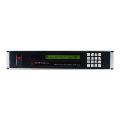
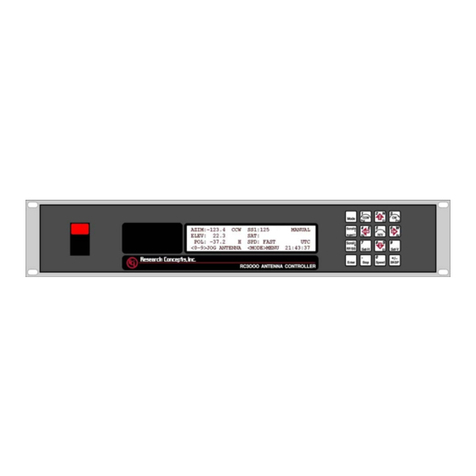
RESEARCH CONCEPTS RC2000C User manual

RC2000C Polar Satellite Tracking
Antenna Controller
V 1.31
Contents Subject To Change
02-19-1996
Research Concepts, Inc.
(913) 422-0210
www.researchconcepts.com


REVISION HISTORY
v 1.01
The software was modified for a proprietary azimuth over elevation mount application.
7.10.95 v 1.02
The RC2000C version 1.00 code has been modified to work for a polar mount with modified declination
adjustment. The motorized latitude angle polar mount is not supported. A different memory map has
been implemented. The RC2KG PLD should be used.
The software has been modified to support conditional compilation of either the polar, elevation over
azimuth, or azimuth over elevation mount versions of the software.
The maximum number of inclined orbit satellites which the controller can track has been increased from 3
to 4.
An error in the initialization of non-volatile memory via the Reset System Data CONFIG mode item was
corrected.
A new manual has been derived from the RC2000C Az/El v 1.00 manual.
11-22-95 v 1.10 Az/El, v 1.11 Polar, v 1.12 El/Az
This release of the software can be compiled to product the following software versions...
* RC2000C Az/El version 1.10 for use with elevation over azimuth type antenna mounts.
* RC2000C Polar version 1.11 for use with polar mounts with a power declination adjustment.
* RC2000C El/Az version 1.12 for use with azimuth over elevation type antenna mounts.
The manual for the RC2000C Az/El was derived from the RC2000C Az/El version 1.00 manual. The
manual for the RC2000C Polar was derived from the RC2000C Polar version 1.02 manual. The manual
for the RC2000C El/Az is the same as is used for the RC2000C Az/El, with an addendum which
describes the few differences between the Az/El and El/Az versions.
The following modifications to the software have occurred:
The track table update flags have been implemented in a different manner. In previous versions of the
software the update flags were implemented in a manner which limited the range of elevation position
values which could be stored in the table to values in the range of 30 to 32767.
The reply to the REMOTE mode Query ID command has been changed to report the various mount types
supported by these versions of the software.
The Remote Communications Protocol documentation has been modified to describe the track related
alarm codes.
New satellite lists have been created.
Two new PC programs, ANTENNA2.EXE and SCALE4.EXE, have been created to support the azimuth
over elevation mount type.
The default value of the Search Width CONFIG mode item has been changed from 5 to 3.
2.26.96 v 1.20 AZ/EL, v 1.21 POLAR, v 1.22 EL/AZ
The polar version of the software was modified to work with a polar mount which employs either a
motorized declination or motorized latitude angle adjustment. A new CONFIG mode prompt named

Mount Type has been added to allow the user to specify either motorized latitude or motorized
declination.
For all versions of the software the maximum number of inclined orbit satellites has been increased to 5
and the maximum total number of satellites has been increased to 38.
The reply to the remote Query ID command has been changed to reflect the new version numbers.
03.23.11
Added RC1KADP Schematic

TABLE OF CONTENTS
CHAPTER 1 INTRODUCTION 1
1.1 Organization of this Manual --------------------------------------------------------------------------------------2
1.2 Before You Begin ---------------------------------------------------------------------------------------------------- 2
CHAPTER 2 BASIC FUNCTION DESCRIPTION 3
2.1 Front Panel-------------------------------------------------------------------------------------------------------------3
2.2 Changing Modes with the MODE Key-------------------------------------------------------------------------4
2.3 Mode Descriptions --------------------------------------------------------------------------------------------------5
2.4 Mode Access ---------------------------------------------------------------------------------------------------------- 8
2.5 Expert Access --------------------------------------------------------------------------------------------------------8
2.6 Auto Pol------------------------------------------------------------------------------------------------------------------ 8
CHAPTER 3 INSTALLATION/SETUP 9
3.1 Before You Begin ---------------------------------------------------------------------------------------------------- 9
3.2 Mechanical and Electrical Installation ------------------------------------------------------------------------ 9
3.3 Optional Polarization Control---------------------------------------------------------------------------------- 13
3.4 Setting Azimuth and Elevation Limits----------------------------------------------------------------------- 15
3.4.1 Motor Drive Polarity ------------------------------------------------------------------------------------ 15
3.4.2 Elevation Movement - Inclined Orbit Operation----------------------------------------------- 15
3.4.3 Setting Limits--------------------------------------------------------------------------------------------- 18
3.5 Slow Speed Adjustment ----------------------------------------------------------------------------------------- 18
3.6 Geo Elevation Position------------------------------------------------------------------------------------------- 19
3.7 Programming Geostationary Satellites --------------------------------------------------------------------- 20
3.8 Auto Pol---------------------------------------------------------------------------------------------------------------- 21
3.9 Sim ultaneous Azimuth and Elevation Movement ------------------------------------------------------- 21
3.10 Installation and Setup Checklist ------------------------------------------------------------------------------ 21
CHAPTER 4 INCLINED ORBIT SATELLITES 23
4.1 Geostationary and Inclined Orbit Satellites --------------------------------------------------------------- 23
4.2 RC2000C Tracking Algorithm---------------------------------------------------------------------------------- 25
4.2.1 STEP_TRACK -------------------------------------------------------------------------------------------- 26
4.2.2 PROGRAM_TRACK------------------------------------------------------------------------------------- 27
4.2.3 Intelli-Search---------------------------------------------------------------------------------------------- 27
4.3 Implementing the Tracking Algorithms--------------------------------------------------------------------- 29
4.3.1 Location Information and Antenna Mount Type ---------------------------------------------- 29
4.3.2 Antenna Scale Factors -------------------------------------------------------------------------------- 29
4.3.3 Antenna Radiation Pattern--------------------------------------------------------------------------- 29
4.3.4 Real Time Clock ----------------------------------------------------------------------------------------- 29
4.3.5 Receiver AGC Signal----------------------------------------------------------------------------------- 30
4.3.6 Antenna Geo Elevation Position ------------------------------------------------------------------- 30
4.4 Configuring the Tracking System ---------------------------------------------------------------------------- 30
4.4.1 AGC Adjustment and Configuration -------------------------------------------------------------- 30
4.4.2 Initializing the Antenna Scale Factors ----------------------------------------------------------- 34
4.4.3 CONFIG Mode Data------------------------------------------------------------------------------------- 36
4.4.4 Initiating a Track on an Inclined Orbit Satellite------------------------------------------------ 38
4.4.5 Tracking Problems ------------------------------------------------------------------------------------- 39
4.5 Inclined Orbit Satellite Setup Checklist -------------------------------------------------------------------- 40
CHAPTER 5 MODES IN-DEPTH FUNCTION DESCRIPTION 41
5.1 MANUAL Mode ----------------------------------------------------------------------------------------------------- 41
5.2 AUTO Mode ---------------------------------------------------------------------------------------------------------- 41
5.3 REMOTE Mode------------------------------------------------------------------------------------------------------ 42

5.4 TRACK Mode---------------------------------------------------------------------------------------------------------42
5.4.1 SEARCH Sub-mode-------------------------------------------------------------------------------------43
5.4.2 STEP TRACK Sub-mode ------------------------------------------------------------------------------43
5.4.3 PROGRAM TRACK Sub-mode-----------------------------------------------------------------------44
5.4.4 TRACK Mode - ERROR Sub-mode ----------------------------------------------------------------44
5.4.5 TRACK MENU---------------------------------------------------------------------------------------------44
5.5 LIMITS Mode ---------------------------------------------------------------------------------------------------------46
5.6 SETUP Mode ---------------------------------------------------------------------------------------------------------47
5.7 RESET Mode ---------------------------------------------------------------------------------------------------------49
5.8 DELETE Mode -------------------------------------------------------------------------------------------------------50
5.9 RE-SY NC Mode------------------------------------------------------------------------------------------------------52
5.10 CONFIG Mode -------------------------------------------------------------------------------------------------------52
5.10.1 AutoPol----------------------------------------------------------------------------------------------------52
5.10.2 Simultaneous Azimuth and Elevation Movement -------------------------------------------53
5.10.3 Remote Communication Parameters------------------------------------------------------------53
5.10.4 Azimuth and Elevation Slow Speed Codes----------------------------------------------------54
5.10.5 Geo Elevation Position-------------------------------------------------------------------------------54
5.10.6 Polarization Motor Option---------------------------------------------------------------------------54
5.10.7 Azimuth and Elevation Drive Options -----------------------------------------------------------55
5.10.8 Time and Date Settings ------------------------------------------------------------------------------57
5.10.9 Signal Strength Parameters ------------------------------------------------------------------------57
5.10.10 Antenna Parameters---------------------------------------------------------------------------------57
5.10.11 Track Mode Parameters ----------------------------------------------------------------------------59
5.10.12 Expert Access Flag ----------------------------------------------------------------------------------60
5.10.13 Reset System Data-----------------------------------------------------------------------------------61
CHAPTER 6 SPECIFICATIONS 63
CHAPTER 7 TROUBLESHOOTING/ALARM CODES 64
7.1 SYSTEM ERROR CODES ----------------------------------------------------------------------------------------64
7.2 TRACK MODE ERRORS------------------------------------------------------------------------------------------66
7.3 OPERATIONAL TROUBLESHOOTING TIPS ---------------------------------------------------------------66
APPENDIX A1 - RESTORING NON-VOLATILE MEMORY 69
APPENDIX A2 - RECOVERING FROM UNEXPECTED MEMORY UPSETS 70
APPENDIX B - EXPERT ACCESS / RESET SYSTEM DATA CODE 71
APPENDIX C – RS-422 SERIAL INTERFACE 72
Appendix D - The RCI RS-422 Interface Specification ----------------------------------------------------------73
Appendix E - RC2000C Communications Protocol --------------------------------------------------------------79
APPENDIX F - CONTROLLING ANTENNAS POWERED BY AC OR LARGE DC
MOTORS 90
APPENDIX G - PROCEDURE FOR DETERMINING SATELLITE INCLINATION 96
APPENDIX H - SCHEMATICS & PCB LAYOUTS 100
WARRANTY 111

RC2000C Polar Tracking Antenna Controller Chapter 1 Introduction 1
Research Concepts, Inc. • 5420 Martindale Road • Shawnee, Kansas 66218-9680 • USA www.researchconcepts.com
Chapter 1 INTRODUCTION
The RC2000C POLAR tracking antenna controller is designed to control an elevation over azimuth
antenna with 36 volt actuators and pulse type position sense feedback. Another member of the RC2000
family, the RC2000C Az/El, is available to provide tracking for an elevation over azimuth mount antenna.
Henceforth, in this manual the term RC2000C is used to refer to the RC2000C POLAR controller.
The RC2000C was designed with the requirements of the commercial user of satellite downlink services
in mind. Here is a brief listing of the capabilities of the RC2000C.
1. The controller utilizes a solid state drive system capable of providing 8 amps to the antenna
actuators. The drive system has built-in over-current sensing with mechanical relay backup to
disconnect the drive from the actuators in the event of a fault.
2. The controller can control polarization via a polarotor type interface. The AUTO_POL feature allows
the polarization to be controlled via a digital input or contact closure supplied by a receiver to the
RC2000C. An RC2KPOL option is available to provide control for a Seavey type two or four port feed
with pot feedback.
3. Position sensing feedback can be supplied by any pulse based sensor - reed switch, Hall effect, or
electro-optical. There is no need for special sensors or actuators. The RC2000C keeps track of both
rising and falling pulse edges from the pulse sensor for increased accuracy.
4. The non-volatile memory can hold position and polarization data for 25 satellites, three of which may
be inclined orbit.
5. The Adapti-Drive variable speed control system allows the user to specify the desired slow speed for
each axis. The Adapti-Drive system will then adjust the actuator voltage (via a pulse width
modulation scheme) to maintain the speed selected by the user. This alleviates the problem of poor
speed regulation with varying direction along a given axis associated with constant voltage slow
speed systems.
6. The RC2000C is equipped with an RS-422 communications port. This allows the controller to
interface with a PC. The communication protocol used is compatible with the popular SA-Bus
protocol. Two IBM PC compatible programs, antenna.exe and scale3.exe., are included with the
controller, on a floppy disk in the back of this manual. The optional AUTOPILOT software package
allows a single PC to control multiple antenna positioners and satellite receivers. An optional RS-232
to RS-422 interface converter, designated RC1KADP, is available to convert the RS-232 interface
(which is standard on PC's) over to the RS-422 interface required for the SA-Bus protocol used on
the RC2000.
7. The tracking scheme used in the RC2000C employs a step track algorithm to build up a track table
which logs the satellite position versus time ( a real time clock powered by a lithium battery is present
in the RC2000C). If the current time corresponds to a time interval for which there are valid entries in
the track table, the controller switches over to a program track algorithm. In this mode the antenna
smoothly tracks the satellite based on position data stored in the track table.
If the satellite transponder goes down while the controller is step tracking, the controller enters a
search mode. The RC2000C has a unique algorithm, denoted Intelli-Search, which determines the
boundaries of a parallelogram shaped region where the controller has determined that the satellite
will be found. This algorithm ensures that the region searched is large enough to include the motion
of the desired satellite and is centered and oriented properly so that satellites adjacent to the desired
satellite are not 'found' during the search.
8. The data which has to be specified by the user to configure the tracking system is straightforward.
The user must specify the time and date, the latitude and longitude of the antenna, the longitude of
each satellite (both geostationary and inclined orbit) programmed into the RC2000C, the maximum
antenna tracking error (in dB), and the antenna size.
2RC2000C Polar Tracking Antenna Controller Chapter 1 Introduction
Research Concepts, Inc. • 5420 Martindale Road • Shawnee, Kansas 66218-9680 • USA www.researchconcepts.com
1.1 Organization of this Manual
This manual is divided into two broad parts, Installation and Reference. The Installation part of this
manual is designed to familiarize the user with the controller and guide him or her through the installation
and configuration of the controller. The Reference portion of the manual gives a detailed description of all
of the features and capabilities of the controller.
The Installation portion of the manual is comprised of Chapters 2 through 4. Chapter 2 explains the user
interface and the basic operation of the unit. Chapter 3 guides the user through the physical installation
and wiring of the unit as well as the initial software configuration. Chapter 4 covers all aspects of tracking
inclined orbit satellites. It begins with a brief discussion of some of the theoretical aspects of the inclined
orbit, and continues with a description of the algorithms used by the RC2000C for tracking inclined orbit
satellites. Chapter 4 concludes with a step by step procedure which guides the user through the entry of
track parameters and the initialization of a track on an inclined orbit satellite.
The Reference portion of this manual is comprised of chapters 5, 6, and 7 as well as the appendices
which follow. These chapters of the manual describe the fields on the screens which the user will
encounter, as well as the data which can be entered at any prompt. After the initial installation, when the
user has become familiar with the operation of the controller, these chapters will probably be the only
ones consulted by the user to handle the routine chores of adding new satellites and deleting old ones.
1.2 Before You Begin
Please read and understand the manual. Time invested in understanding the installation and operation of
the controller will insure satisfactory results. The unit has been tested thoroughly and will work accurately
and reliably if it is installed and configured properly. There is an old saying in the controller business -
"Garbage in, garbage out". Be very careful when entering data into the controller. For example, if the
longitude data for a geostationary satellite is entered incorrectly, the controller will accurately position
itself on that satellite. If however, at a later time, a track is initiated on an inclined orbit satellite in the
vicinity of that geostationary satellite, the incorrect longitude may be used to calculate incorrect step track
angles and unsatisfactory results will occur.

RC2000C Polar Tracking Antenna Controller Chapter 2 Basic Function 3
Research Concepts, Inc. • 5420 Martindale Road • Shawnee, Kansas 66218-9680 • USA www.researchconcepts.com
Chapter 2 BASIC FUNCTION DESCRIPTION
This chapter describes the controller's front panel layout, user interface and basic operation. When the
user has completed this chapter, he or she should have a basic understanding of the various operating
modes of the unit, and be able to use the keyboard and liquid crystal display (LCD) to navigate through
those modes.
2.1 Front Panel
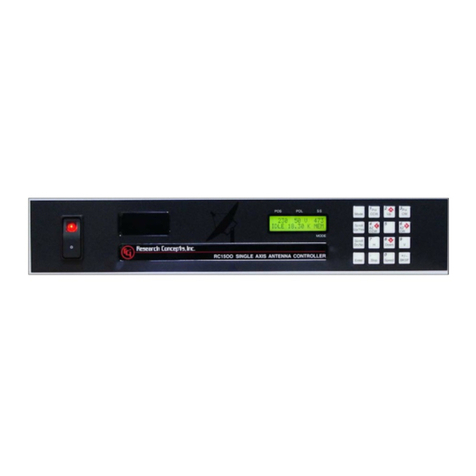
The front panel (figure 2.1) of the RC2000C contains an ON/OFF switch, a 2 row by 40 column backlit
LCD, and a 4 by 4 matrix keypad with tactile feedback. An AC line circuit breaker is built into the ON/OFF
switch, and a 12 amp circuit breaker (located on the back of the unit) protects the controller's 36 volt
actuator drive circuits. When a circuit breaker of this type trips, it will protrude from its mounting bezel.
To reset a circuit breaker, turn the power switch off, wait a few minutes for the circuit breaker to cool
down, then depress the breaker so that it latches and is even with the bezel.
Figure 2.1
The field in the upper right hand corner of the LCD is reserved for the display of the current mode of the
controller. The various modes are introduced in the following section. If an error condition is active, an
error message will periodically flash across the bottom row of the display. Error messages are discussed
in chapter 7. Chapter 5 explains the contents of every field on the display for all of the various controller
modes.
An examination of the keyboard in figure 2.2 reveals that many of the keys have 2 or more labels. The
function of each key is determined by the current operational mode of the controller. The various modes
are discussed in the following section.
Figure 2.2

4RC2000C Polar Tracking Antenna Controller Chapter 2 Basic Function
Research Concepts, Inc. • 5420 Martindale Road • Shawnee, Kansas 66218-9680 • USA www.researchconcepts.com
MODE
Toggling this key allows the user to set the desired mode of the controller. There are two groups
of modes: Operational = MAN, AUTO, REMOTE, or TRACK; or Programming = LIMITS,
CONFIG, etc. To change from one GROUP to the other, HOLD THE MODE KEY FOR FIVE
SECONDS, then toggle between the options available.
SCROLL UP/SCROLL DOWN
These keys are used to scroll up or down through a list of items.
YES/NO
These keys are used to supply an answer to a yes or no question.
ENTER
This key is used to select an entry from a list, terminate a prompt for some action by the user, or
to complete the entry of numeric data.
0-9/DECIMAL POINT (with the stop key)/BKSP
These keys are used for numeric entry. The BKSP key causes the cursor to move one column to
the left writing over the character which was there.
SPEED
This key toggles the az/el speed from fast to slow and vice versa.
ARROW KEYS - 2/4/6/8
These keys are used to manually jog the antenna in some modes. The left and right arrow keys
jog the antenna east and west in azimuth, respectively, while the up and down arrow keys jog the
antenna up or down in elevation.
E/W/N/S
These direction keys, E east, W west, N north, and S south are used to specify a direction when
the user is entering latitude or longitude data.
CCW/CW/H/V
These keys control the Polarization. The CCW and CW keys skew the polarization control device
counterclockwise and clockwise. The H and V keys are used to either select or specify the
polarization position associated with a given satellite.
Note that all of these keys are not active simultaneously. The function of each key is dependent on the
current mode of the controller. In some modes certain keys are ignored.
2.2 Changing Modes with the MODE Key
The user can switch the current controller mode by use of the MODE key. The MODE key is always
active - when the MODE key is depressed and released, the controller's current mode will change.
The modes are divided into two groups, referred to as mode groups. The Operational mode group
consists of the MANUAL, AUTO, REMOTE, and TRACK modes. The Programming mode group consists
of the SETUP, RESET, DELETE, RE-SYNC, CONFIG, and LIMITS modes. The Programming modes
are typically only used during system installation and configuration. The Operational modes are the ones
used in everyday operation of the controller.

RC2000C Polar Tracking Antenna Controller Chapter 2 Basic Function 5
Research Concepts, Inc. • 5420 Martindale Road • Shawnee, Kansas 66218-9680 • USA www.researchconcepts.com
To switch between modes in a group, press the MODE key and release. The new mode will display in
the upper right hand corner of the display. To switch to the other group of modes, hold the MODE key in
for five seconds and release. This scheme was designed to help keep inexperienced personnel from
inadvertently changing any of the programmed parameters specified during system setup. It is also
recommended that Expert Access be used to safeguard the integrity of the data (see section 2.5).
2.3 Mode Descriptions
The mode system on the RC2000C antenna controller resembles the menu system used with many
personal computer (PC) programs. On a PC program a menu system allows the user to perform
operations or to enter in data. The user must navigate through the menu structure to the particular menu
which allows access to the function or data that the user wishes to manipulate. On the RC2000C the
mode which is currently active is always displayed in the upper right hand corner of the LCD. Here is a
summary of the modes implemented on the RC2000C.
MANUAL
AZ:159.4 EL: -327 PL: 723 H S:635 MANUAL
SBS 2 97.0 W SPEED:FAST
In manual mode you can:
1. Jog the antenna in elevation and azimuth using the ARROW KEYS
2. Toggle the speed from fast to slow (and vice versa) with the SPEED key.
3. Jog the polarization with the CCW/CW keys.
4. Use the H/V keys to toggle between the preset H and V polarizations of the satellite which was the
last target of an AUTO move.
When MANUAL mode is active the following information is displayed on the top row of the LCD: azimuth
position (AZ), elevation position (EL), polarization position (PL), and the current signal strength (SS). The
signal strength is derived from a receiver automatic gain control (AGC) output.
The bottom row of the LCD displays the name and longitude of the satellite that was the last target of an
AUTO move, and either the FAST or SLOW banner to indicate the speed which will be used for jogging
the antenna.
AUTO
SELECT A SATELLITE: PANAMSAT-1 AUTO
USE SCROLL UP/DOWN, ENTER TO SELECT
This mode allows the user to automatically position the antenna on any satellite that has been
programmed into memory. The list of programmed satellites is reviewed via the SCROLL UP/DOWN
keys, and the ENTER key initiates the automatic move. The STOP key will terminate the move. When
the antenna is positioned, the controller will switch to MANUAL mode for a geostationary satellite, and
track mode is activated for an inclined orbit satellite.
REMOTE
AZ: 1291 EL: 0 P0L: 15 H REMOTE
SAT: SBS 2
In this mode the controller receives and acts on commands received via the communications port. This
mode can only receive control if enabled via a CONFIG mode item. The only key which is active is the
MODE key, which can be used to switch to a different mode.

6RC2000C Polar Tracking Antenna Controller Chapter 2 Basic Function
Research Concepts, Inc. • 5420 Martindale Road • Shawnee, Kansas 66218-9680 • USA www.researchconcepts.com
SETUP
POSITION ANTENNA, SELECT SETUP
SATELLITE USING SCROLL UP/DOWN,HIT ENTER
This mode allows the user to store satellite azimuth and elevation positions and horizontal/vertical
polarization values into the controller's non-volatile memory. Once stored in memory, the satellite is
available for recall by AUTO mode.
When SETUP mode is invoked:
1. the user peaks the antenna up on the desired satellite
2. the SCROLL keys are used to scroll through a list of satellite names stored in the controller's EPROM
memory. When the desired name is found,
3. the ENTER key assigns it to the current position and polarization. (If the user wishes to assign a
name which is not stored in the satellite's EPROM memory, the USER can manually enter the name.
See page 56.)
The user is then prompted to specify:
1. the satellite longitude,
2. whether or not the satellite is in an inclined orbit (and if so, the current inclination of the satellite's
orbital plane to the earth's equatorial plane - more on this in the chapter on tracking), and
3. the H and V polarization values for the satellite.
When the user has entered in all of the requested data, the controller will respond with "DATA
ACCEPTED", and the user can jog the antenna to another satellite and repeat the procedure. If the
satellite just entered was an inclined orbit satellite, the controller will initiate a TRACK.
RESET
AZ: OK EL: OK PL: OK RESET
RESET AXIS: 1-AZ, 2-EL, 3-POL
This mode allows the user to examine the error status of the motor drive circuits and reset them if a fault
has occurred. The drive systems of each axis are independent. A DRIVE error indicates that the drive
circuits detected an over current fault and shut down. A JAMMED error indicates that the antenna
actuators were commanded to move but no movement was detected. A RUNAWAY error indicates that
antenna movement was detected when the actuators were not energized. A SENSOR error indicates
backwards movement of the pot. (Polarization errors will only be shown if the rotating feed drive option
has been enabled.) Any error condition can be reset by pressing the key designated on the bottom line of
the display. Errors are covered in chapter 6.
DELETE
SELECT A SATELLITE: PANAMSAT-1 DELETE
USE SCROLL UP/DOWN, ENTER TO SELECT
This mode allows the user to delete satellites from non-volatile memory. The SCROLL UP/DOWN and
ENTER keys are active.
RE-SYNC
SELECT A SATELLITE: PANAMSAT-1 RE-SYNC
USE SCROLL UP/DOWN, ENTER TO SELECT

RC2000C Polar Tracking Antenna Controller Chapter 2 Basic Function 7
Research Concepts, Inc. • 5420 Martindale Road • Shawnee, Kansas 66218-9680 • USA www.researchconcepts.com
The antenna azimuth and/or elevation position can be corrupted by any number of causes (sensor failure,
lightning strike, faulty shield connection, etc). If there is an error in the position counts, the controller
cannot properly position itself on the satellites stored in non-volatile memory, and the limits are not valid.
In this situation, it is necessary to re-synchronize the controller's internal position counts.
To do this, the operator positions the antenna on a known satellite which has previously been stored in
the controller's non-volatile memory (preferably a Ku band satellite, since the beamwidth of the antenna is
narrower at Ku band than at C band). The user then activates RE-SYNC mode, and uses the SCROLL
UP/DOWN keys to select the satellite name with which the antenna is currently aligned. When the
ENTER key is hit, the controller's internal position counts for that satellite are initialized to the current
position, and a corresponding adjustment is made to all other satellite positions across the arc.
CONFIG
AUTOPOL ENABLE:* CONFIG
0-DISABLE, 1-ENABLE ENT,BKSP,SCRLL ^v
This mode allows the user to view and enter configuration data into the controller. This data is stored in
non-volatile memory and is used to set certain parameters and enable or disable certain controller
options. The following parameters and options are controlled or configured via data entered into the
controller from CONFIG mode:
AUTOPOL
communication port parameters
simultaneous azimuth/elevation movement
time and date
geo elevation position
az/el slow speed control parameters
polarization options
az/el drive systems options
antenna parameters
tracking system setup and control parameters
In CONFIG mode, the SCROLL UP/DOWN keys are used to select the parameter to be viewed or
modified. If asterisks are displayed in the parameter field, it means that the present value is invalid. It
can be modified using the numeric keypad to key in a new value, followed by ENTER. (For the
modification to take effect the numeric entry must be terminated with the ENTER key.) The message in
the lower left hand corner of the display gives the user data entry instructions.
LIMITS
AZ: 5000 EL: 5000 SS1,2: 2, 1 LIMITS
7 - SET EAST LIMIT 9 - SET DOWN LIMIT
This mode allows the user to jog the antenna to any azimuth or elevation position without regard to any
existing limits, and initialize the east and west and/or down and up limits. Once the limits are set the
antenna cannot be moved (except in LIMITS mode) to a position that is not within the region defined by
the down, up, east and west limits.
To set the azimuth limits, the user would first move the antenna to the desired east limit, hit ENTER to set
the limit, then move the antenna to the desired west limit and hit ENTER to set that limit. (Whenever the
limits are reset, the east and down limits are initialized to a position count of 30.)
TRACK
AZ: 1344 EL: -46 PL: 73 V S:621 TRAK K
GSTAR 3 PROGRAM IDLE 15.56.0-MENU
TRACK mode is activated to track an inclined orbit satellite. TRACK mode is slightly different than the
other modes described above in that TRACK mode cannot be reached directly through the use of the
MODE key. TRACK mode can be entered only via the SETUP or AUTO modes. TRACK mode is
described in Chapter 4.

8RC2000C Polar Tracking Antenna Controller Chapter 2 Basic Function
Research Concepts, Inc. • 5420 Martindale Road • Shawnee, Kansas 66218-9680 • USA www.researchconcepts.com
More detailed information is available concerning each of the modes described above in Chapter 5 of this
manual.
2.4 Mode Access
Access to some modes is restricted in some circumstances. Here are the conditions which can restrict
access to certain modes:
1. TRACK mode can only be entered via the AUTO or SETUP modes - it cannot be entered via the
MODE key. When TRACK mode is active it is treated as if it were in the operational mode group. If
TRACK mode is active and the user presses the MODE key, control will transfer to the MANUAL
mode. If TRACK mode is active and the user holds the MODE key in for five seconds, control will
transfer to SETUP mode.
2. REMOTE mode is only accessible when the Remote Mode Enable CONFIG mode item is set to 1.
When enabled, REMOTE mode can be activated either via the MODE key or by the receipt of a
command on the serial port. Note that most commands received via the serial port may be
processed while TRACK mode is active.
3. The expert access system can restrict access to certain modes. The intent is to avoid corruption of
the operating parameters by inexperienced personnel. The expert access system is described in the
next section.
2.5 Expert Access
An Expert Access flag is maintained by the controller. The user can inspect and change the state of this
flag via the CONFIG mode Expert Access item. When the flag is set (1) the user has access to all
controller modes (subject to the state of the Remote Mode Enable and Rotating Feed Present flags
described in the preceding paragraph). When the Expert Access flag is reset (0), the user only has
access to the MANUAL, AUTO, REMOTE, RESET, and CONFIG modes.
The Expert Access flag also controls access to CONFIG mode items. When the flag is reset (0), the user
only has access to the Autopol Enable, Simultaneous Az/El Enable, and Expert Access CONFIG mode
items. The user can toggle the state of the Expert Access flag by entering a 5 digit code at the CONFIG
mode 'EXPERT ACCESS' item. This 5 digit code is contained in a removable appendix B at the end of
this manual, to safeguard from any accidental corruption of operating parameters by inexperienced
personnel. Note that the Expert Access flag is set whenever the controller's memory is cleared via the
Reset System Data CONFIG mode item.
2.6 AutoPol
The AutoPol feature slaves the RC2000C polarization control to an output derived from a satellite
receiver. The RC2000C has an AutoPol input accessible via connector J1 on the back of the unit. When
the controller is operating in MANUAL or REMOTE modes, this input is monitored and the polarotor is
controlled according to a digital level present at this input.
To configure the controller for AutoPol operation, the user must have:
1. a suitable output available on the satellite receiver which is connected properly to the AutoPol input of
the RC2000C,
2. the polarity of the AutoPol input must be specified (from CONFIG mode), and
3. the AutoPol feature must be enabled (also from CONFIG mode).
When the polarity of the AutoPol input is specified, the user is informing the controller that a given
AutoPol input level (high or low) corresponds to vertical polarization. Configuring the AutoPol system
during installation is covered in more detail in chapter 3, and the CONFIG mode prompts which enable
and specify the polarity of the AutoPol input are described in Chapter 4 in the CONFIG mode section.

RC2000C Polar Tracking Antenna Controller Chapter 3 Installation/Setup 9
Research Concepts, Inc. • 5420 Martindale Road • Shawnee, Kansas 66218-9680 • USA www.researchconcepts.com
Chapter 3 INSTALLATION/SETUP
This chapter guides the installer through the installation and the initial software setup. The procedures
outlined in this chapter cover the mechanical and electrical installation of the unit, the setup of optional
polarization control devices, setting the azimuth and elevation limits, determining the azimuth and
elevation slow speed parameters, and programming the geostationary satellites into non-volatile memory.
3.1 Before You Begin
Before installing the unit the installer must ensure that the line voltage is correct, the controller's memory
has been cleared, and that he or she is familiar enough with the mode system described in Chapter 2 to
place the controller in any desired mode. All units are shipped from the factory with memory cleared, and
a line cord appropriate for the line voltage selected.
If the line cord received with the unit is not appropriate for the power available at the installation site, the
installer should check the controller to ensure that the proper line voltage has been selected.
The RC2000C can be configured to operate on either 115 VAC or 230 VAC. The AC input voltage the
unit is currently configured for is displayed in a window located in the fuse holder. To change the AC
input voltage selection, remove the fuse holder and reverse the jumper assembly (on which the ‘115’ and
‘230’ labels are located). Switch the power off at the front panel. Remove the IEC power cord from the
back panel power entry module. With a small straight-blade screwdriver, remove the fuse drawer from
the power entry module. With the same tool, remove the small plastic circuit card. Rotate the card so
that the desired operating voltage will be displayed through the front of the fuse drawer and reinsert the
card so that it firmly seats into the power entry module. Replace the fuse with one of the appropriate size
for the new operating mains voltage The fuse holder is designed to accommodate 1/4” by 1 1/4” fuses.
For both 115 VAC and 230 VAC operation, use 6 amp, ceramic, fast blow fuses.
RCI part # F-6A-FB-C, Bussman part # ABC-6, Littlefuse part # 314006.
When the AC line voltage has been verified, and before any of the antenna wiring has been connected,
the installer should become familiar with the controller's user interface. It is not necessary to understand
every aspect of the controller's operation to install the unit, but the installer should be familiar with the
mode structure of the RC2000C and be able to use the MODE key to place the controller in any of the
modes described in Chapter 2.
When the unit is powered up, it should be verified that the controller goes to LIMITS mode ('LIMITS'
displayed in the upper right hand corner of the LCD). Before the controller is shipped from the factory,
the memory is cleared and the azimuth and elevation limits are invalidated. Whenever the unit is
powered up and the limits are invalid, the controller automatically places itself in LIMITS mode. If the unit
does not power up in LIMITS mode the installer should perform a system reset to place the controller into
a known state before proceeding with the installation.
To perform a system reset:
1. Use the MODE key to place the controller into CONFIG mode ('CONFIG' displayed in the upper right
hand corner of the LCD).
2. Use the SCROLL keys to bring up the Reset System Data screen. If the Reset System Data item
does not appear, the Expert Access flag (see section 2.5) may need to be reset.
To inspect the status of the Expert Access flag, use the SCROLL DOWN key (while still in CONFIG
mode) to bring up the Expert Access CONFIG mode item. If a 1 does not appear in the data entry
field, enter the 5-digit code described in section 2.5 to toggle the Expert Access flag on. This will
allow access to the Reset System Data CONFIG mode item.
3. At the Reset System Data screen enter the same 5 digit code followed by the ENTER key.

10 RC2000C Polar Tracking Antenna Controller Chapter 3 Installation/Setup
Research Concepts, Inc. • 5420 Martindale Road • Shawnee, Kansas 66218-9680 • USA www.researchconcepts.com
3.2 Mechanical and Electrical Installation
This section covers the mechanical and electrical installation of the unit. Use 4 #10-32 mounting screws
to secure the unit to a standard 19" rack. Please refer to figures 3.1, 3.2, and 3.3 for diagrams of the
controller back panel and electrical connections.
The following electrical connections must be made:
Azimuth and Elevation Motor Drive - 4 wires (2 for each axis)
These cables connect the controller to the azimuth and elevation motors. The conductors must be sized
appropriately so that sufficient voltage is supplied to the motors. The voltage supplied to the motors will
be the output voltage from the controller less the voltage drop caused by the resistance of the wires.
The output voltage of the controller is a function of the current supplied to the motors. The voltage drop
in the wires connecting the controller to the antenna is determined by the wire size, the wire length, and
the current supplied to the motors. Figure A in the back of this manual shows the relationship between
the controller output voltage and load current.
The following tables show the separation between the controller and the antenna which will result in 28
and 22 volts being applied to the antenna drive motors as a function of motor current and wire gauge.
The tables take into account the controller output loading and resistive losses in the conductors.
Separation (in feet) between controller and antenna which will result in 28 volts being applied to the
motors: Motor Wire Gauge
Current 16 14 12 10
2 amps 600 950 1500 2410
3 amps 340 520 830 1350
4 amps 220 340 550 880
6 amps 90 140 230 340
8 amps 30 40 70 120
Separation (in feet) between controller and antenna which will result in 22 volts being applied to the
motors: Motor Wire Gauge
Current 16 14 12 10
2 amps 970 1530 2430 3930
3 amps 580 920 1460 2370
4 amps 400 640 1020 1650
6 amps 220 340 550 880
8 amps 120 190 310 500
A typical 36 volt actuator will draw 2 to 4 amps and will run at voltages down to about 12 volts.
PolarotorTM - 3 wires in a shielded cable.
Connect the polarotor as shown in either figure 3.2 or 3.3. Shielded cable is required to minimize noise
pickup.
NOTE: A SHIELDED CABLE IS REQUIRED FOR THE POLAROTORTM. THE SHIELD MUST BE
CONNECTED TO J1-9 ON THE BACK OF THE CONTROLLER AND MUST NOT BE CONNECTED AT
THE ANTENNA.
Azimuth and Elevation Position Sense
If reed switch sensors are used, each axis requires 2 wires in a shielded cable. If Hall effect sensors are
used, each axis requires 3 wires in a shielded cable. Shielded cables are required to minimize noise

RC2000C Polar Tracking Antenna Controller Chapter 3 Installation/Setup 11
Research Concepts, Inc. • 5420 Martindale Road • Shawnee, Kansas 66218-9680 • USA www.researchconcepts.com
pickup which can result in antenna positioning errors. Please refer to figure 3.2 for reed sensor
connections and figure 3.3 for Hall Effect sensor connections.
NOTE: SHIELDED CABLES ARE REQUIRED FOR THE POSITION SENSORS. THE SHIELDS
MUST BE CONNECTED TO PINS J1-4 OR J1-6 ON THE BACK OF THE CONTROLLER AND MUST
NOT BE CONNECTED AT THE ANTENNA.
Position count errors due to improper use of the shield on the position sense lines is one of the most
frequent problems encountered during the installation of the RC2000C. Here are the problems that are
encountered:
1. A shielded cable was not used for the position sense wires.
2. The shield is not connected at connector J1 on the rear panel of the RC2000C.
3. The shield is connected to earth ground at the antenna. This results in ground currents flowing in the
shield. The shield must not be connected to anything at the antenna.
4. The insulator on the sensor cable is broken and the shield is grounded to something. As in #3, this
results in ground currents.
5. The sensor cable is spliced but the shield has not been spliced, or the shield is spliced but is also
shorted to earth ground.
See the Operation Troubleshooting Tips section of Chapter 7 for more information on count problems.
Figure 3.1 RC2000C Back Panel Diagram
J3
1
AGC POTS
COMM
J1
O
F
F
S
E
TN
I
A
GG
A
I
N
T
E
S
F
F
O
AGC1AGC2 17
.
5
V
E
S
L
U
P
N
T
R
V
H
+
Z
A
+
L
E
E
L
-
A
Z
-
N
T
R
2
C
G
A
C
G
A
AZ DRIVE (2)
EL DRIVE (2)
SKEW
AUTOPOL INPUT
SENSORS
AGC INPUTS
G
N
D
G
N
D1
Z
A
1
L
EE
L
2
A
Z
2
1
J2
A
2
1
BREAKER
DRIVE
RC2000 Back Panel
EIC Input Power
J4
RTN REF
SIG DRIV E
12345

12 RC2000C Polar Tracking Antenna Controller Chapter 3 Installation/Setup
Research Concepts, Inc. • 5420 Martindale Road • Shawnee, Kansas 66218-9680 • USA www.researchconcepts.com
Figure 3.2 Reed Sensor Diagram
Figure 3.3 Hall Effect Diagram

RC2000C Polar Tracking Antenna Controller Chapter 3 Installation/Setup 13
Research Concepts, Inc. • 5420 Martindale Road • Shawnee, Kansas 66218-9680 • USA www.researchconcepts.com
3.3 Optional Polarization Control
With the RC2KPOL option, the RC2000C can control a 24 volt DC polarization motor with potentiometer
position feedback. If an optional polarization device is not installed, make sure that the Rotating Feed
Present CONFIG mode item is set to 0, and proceed to the next section.
*** CAUTION ***
Before using a Seavey rotating feed with the RC2000, it is recommended that the user verify that the
feed's range of mechanical movement is within the position sense potentiometer's range of mechanical
movement. If the mechanical limit of the pot is reached before the mechanical limit of the feed is
reached, the torque of the motor can destroy the pot. The pot used with the Seavey feed is a Spectrol
model 533 (1K ohm, 3 turn).or a Contelec PD2205-5ko\\KO/J (5k ohm, 5 turn.) To see if the
potentiometer is centered properly, the following procedure may be performed on a workbench.
Verifying Pot Center Position
1. Verify the total resistance of the potentiometer. This may be done by either reading the value written
on the side of the pot, or by measuring between the two non-wiper terminals of the pot. For the
Spectrol pot this will be terminals 1 and 3.
2. Connect an ohm meter between the wiper of the pot (terminal 2 on the Spectrol or Contelec) and one
of the other two terminals. Note that when the shaft position of the pot is near one of the pot's
mechanical limits, the ohm meter will read either less than 25 ohms, or the value found in step 1.
3. With a bench power supply, automobile battery charger, or some other voltage source, carefully apply
power to the feed's DC motor to move it towards one mechanical limit or the other. (Note that the
feed motor for the Seavey feed nominally requires 24 volts DC at approximately 150 mA. The feed
motor should move with an applied voltage of 6 to 12 volts DC.)
While movement is in progress, monitor the ohm meter to insure that the pot's mechanical limit is not
reached. If the ohm meter indicates that the pot's mechanical limit is being approached, quickly
disconnect the power source and perform the procedure outlined in the section entitled "Centering
the Pot".
4. If the feed can safely move to one of its mechanical limits, reverse the power supply leads and move
the pot towards the other mechanical limit. Once again, monitor the ohm meter to insure that the
pot's mechanical limits are not exceeded. If the feed cannot be moved to its mechanical limit without
approaching the pot's mechanical limit, perform the procedure outlined in the section entitled
"Centering the Pot".
Centering the Pot
The procedure outlined here may be used to center the feed's range of travel within the pot's mechanical
limits.
1. Find the total resistance of the pot. See step (1) above.
2. Loosen up the allen screw which holds the shaft of the pot to the gear.
3. Apply power to the feed motor (as in step (3) above) to center the feed in the middle of its range of
travel. As the feed rotates, make sure that the shaft of the pot does not turn.

14 RC2000C Polar Tracking Antenna Controller Chapter 3 Installation/Setup
Research Concepts, Inc. • 5420 Martindale Road • Shawnee, Kansas 66218-9680 • USA www.researchconcepts.com
FIGURE 3.3 POLARIZATION CONTROL
4. When the feed has been centered in its range of travel, connect the ohm meter between the wiper
and one of the other terminals of the pot. Rotate the shaft of the pot until the resistance read from the
ohm meter is one half of the value of the pot's total resistance (obtained in step (1)).
5. Tighten the allen screw and verify that the pot is properly centered by performing the procedure
above entitled "Verifying Pot Center Position".
Use the following procedure to configure the RC2000C for use with a 24V DC polarization motor.
1. Connect the polarization/sensor assembly as shown in figure 3.4. Note that shielded cable is
required for the sensor and that the shield MUST be connected to the GROUND terminal (1) at the
back of the controller and MUST NOT be connected to anything at the antenna.
2. The CONFIG mode item Rotating Feed Present must be set to YES (1). Activate CONFIG mode and
use the SCROLL DOWN key to bring up the Rotating Feed Present item and key in a 1 followed by
the ENTER key. (If the Rotating Feed Present item is not accessible in CONFIG mode, the Expert
Access flag has been reset. If this occurs, perform a system reset as described in section 3.1.)
3. In this step the polarity of the polarization motor and sensor wiring is checked.
The motor polarity is somewhat arbitrary. The polarization jog keys are labeled CW and CCW. The user
is free to define the direction sense as they wish. To change direction or motor rotation associated with
CW and CCW, swap the motor drive wires attached to connector J4 terminals 4 and 5 (DRIVE). The
important thing is that when the polarization motor is jogged CCW, the position count MUST INCREASE.
If this is not the case, the wires attached to the connector J4 terminals labeled 3 (REF) and 1 (RTN) must
be reversed. Note that the shield must always be connected to the RTN terminal.
To check the polarity of the polarization motor, the rotating feed limits must be set so that unrestricted
movement of the feed is possible. To achieve this, the Rotating Feed CW Limit CONFIG mode item must
be set to 0, and the Rotating Feed CCW Limit must be set to 1023. These items are accessed in a
manner identical to that described in the previous step of this procedure.
The polarization motor may be jogged in MANUAL mode. Jog the pol motor and make sure that
movement is in the proper direction - position count decreasing for CW movement, and increasing for
CCW movement. Note that once the rotating feed limits have been set as described above, there are no
limits on polarization movement. The user must be careful to not move the motor past a limit. Damage to
Other manuals for RC2000C
1
Table of contents
Other RESEARCH CONCEPTS Controllers manuals

RESEARCH CONCEPTS
RESEARCH CONCEPTS RC4080 Use and care manual

RESEARCH CONCEPTS
RESEARCH CONCEPTS RC2000A DUAL AXIS User manual

RESEARCH CONCEPTS
RESEARCH CONCEPTS RC3000 User manual

RESEARCH CONCEPTS
RESEARCH CONCEPTS RC2000C User manual

RESEARCH CONCEPTS
RESEARCH CONCEPTS RC4500 User manual

RESEARCH CONCEPTS
RESEARCH CONCEPTS RC4000 User manual

RESEARCH CONCEPTS
RESEARCH CONCEPTS RC4000 User manual

RESEARCH CONCEPTS
RESEARCH CONCEPTS RC1500B User manual

RESEARCH CONCEPTS
RESEARCH CONCEPTS RC4500 Use and care manual

RESEARCH CONCEPTS
RESEARCH CONCEPTS RC3050 User manual