resideo LPK1000T1003 User manual

LifeWhere Gateway, Indoor
(Furnace), and Outdoor (AC)
Instructions for:
Model # Description New Install Add to/Replace in Existing System
LPK1000T1003 LPKIT (FURNACE + AC) x x
LPK1000T1004 LPKIT (FURNACE ONLY) x x
LPK1000T1005 LPKIT (AC ONLY) x x
LPX1100T1000 LPX (1) Sense Port, INDOOR
ENCLOSURE
x
LPX1200T1000 LPX (1) Sense Port, OUTDOOR
ENCLOSURE
x
LPG1000T1000 LifeWhere Gateway x
Note: Some sections of this manual may not be applicable, depending on the kit
Read before installing. Visit resideo.com/pro/lifewhere for up to date instructions, videos, LED
Codes and troubleshooting information.
When Installing this Product
Read these instructions carefully. Failure to follow them could damage the product and cause a
hazardous situation.
Check the ratings given in the instructions and on the product to make sure the product is suitable
for your application.
Installer must be a trained, experienced service technician.
After installation is complete, check out product operation as provided in these instructions.
Cautions
Electrical shock or equipment damage may occur.
Disconnect power supply before beginning installation.
34-00048-03
Package Includes:
LPG1000T1000
• Power Supply with Holster
LPX1100T1000
• R&C Power Cable
• 20Amp CT (Sensing)
• Adhesive Mounting Strip
LPK1200T1000
• 50Amp CT (Sensing)
• 50Amp CT (Charging)
• Mounting Screws
GATEWAY
M38445
M38518
INDOOR
SENS
OR HUB CT
R AND C
CABLE
20A
M38519
OUTDOOR
SENSOR HUB CTS
50A 50A

34-00048—03 2
General Process
1. Homeowner Downloads App while Technician Gathers Furnace & AC Info (as applicable).
2. Technician Guides Homeowner Through LifeWhere Device Scanning & Data Entry.
3. Gateway Location is Selected and Homeowner Passes Configuration to Gateway via Mobile
App.
4. Technician then completes installation of Sensor Hub(s) on Furnace and AC (as applicable)
Getting Started
1. Ask the customer to download the LifeWhere Home app and create an account. The
LifeWhere Home app is available for download from theApp Storeand the Google Play Store.
2. While the customer is doing that, find the furnace and oustide airconditioning unit. Write
down or take a photo of the following:
Furnace Air Conditioner
Make (Goodman, Carrier, etc.)
Model (GM123B89, etc)
Serial #
Installation or Manufacturing Date
Technician Tools & Supplies Needed
• Drill
• Screwdriver
• Zip Ties
Application diagram
M38448
LIFEWHERE
GATEWAY
INDOOR
SENSOR
HUB
CONNECTED
IN FURNACE
CONNECTED
IN AC UNIT
MOUNTED
ON HOME
EXTERIOR
IFC
HOME
FURNACE
SENSING
CT
RC
MOUNTED ON
FURNACE
WI-FI
ROUTER CLOUD
OUTDOOR
SENSOR HUB
AIR
CONDITIONER
SENSING
CT
CHARGING
CT
Before you begin
Verify the customer:
• is home
• has his/her mobile device
• has his/her Wi-Fi credentials
• has access to his/her email

3 34-00048—03
M38480
Model:LPG1000T1000
1
MACID:f8f005D3e4dc
S/N:193516489
ContainsFCCID:2ADHKATWINC1500/OA3MRF89XAM9A
ContainsIC:20266-WINC1500UB/7693A-89XAM9A
Countryof origin:/Pays d’origine:Mexico
PairReset
Sensor Hub
Model:LPG1000T1000
1
MACID:f8f005D3e4dc
S/N:193516489
ContainsFCC ID:2ADHKATWINC1500/OA3MRF89XAM9A
ContainsIC:20266-WINC1500UB/7693A-89XAM9A
Countryof origin:/Pays d’origine:Mexico
LifeWhere Gateway
Status Pair
Model:LPG1000T1000
1
MACID:f8f005D3e4dc
S/N:193516489
ContainsFCCID:2ADHKATWINC1500/OA3MRF89XAM9A
ContainsIC:20266-WINC1500UB/7693A-89XAM9A
Countryoforigin:/Paysd’origine :Mexico
BATTERIES
1- - - C
LifeWhere SensorHub
Pair
Reset
Model:LPG1000T1000
1
MACID: f8f005D3e4dc
S/N:193516489
ContainsFCC ID:2ADHKATWINC1500/OA3MRF89XAM9A
ContainsIC:20266-WINC1500UB/7693A-89XAM9A
Countryoforigin:/Paysd’origine:Mexico
Gateway
(QR Code on Side)
Indoor Sensor Hub
(QR Code on Side)
Outdoor Sensor Hub
(QR Under Cover and Back of Unit)
Scan devices
1. Open the box containing the LifeWhere hardware devices.
2. Ask the customer to login to their LifeWhere Home app account.
3. In the app, scan the QR code on the label of each device, name it and add it. Do this for all
devices in the box.
NOTE: Place yourphone camera close enough to the label to scan the entire QR code. Camera
should be about 1-3 inches away from the QR code. Try to get the horizontal red line in middle of
the QR code. You must acceptcamerapermissionsinthe app to enable scanning.
The following table give examples of each required mobile app entry field:
LifeWhere Home App
Entry Field
Notes:
First Name Homeowner Info to Create Account
Last Name
Phone Number
Email
Account Password
Gateway Nickname Example: Main Gateway Used to distinguish between multiple Gateways in a home.
Indoor Sensor Hub Nickname Example: Basement SH Used to distinguish between multiple Sensor Hubs in a home.
Outdoor Sensor Hub Nickname Example: Outdoor SH Used to distinguish between multiple Sensor Hubs in a home.
Asset (Appliance) Nickname Example: Main Furnace Used to name the Asset (Appliance) being monitored.
Asset (Appliance)Type Default set based on Sensor Hub Model. LPXx1 = Furnace, LPXx2= Air Conditioner
Appliance Make Example: Goodman, Carrier, Trane, Lennox Manufacturer/Brand of the Appliance
Appliance Model Example: KG7SC 072D-248 Detailed Model # of each appliance
Appliance Serial Number Example: KGD110902612 Detailed Serial Number of each appliance
Manufactured Date Manufacture Date -OR- Installation Date. Note: Manufacture date may be part of the Serial #
Port Configuration Default set to Main Power Used to identify what data is being monitored from the appliance.
Home Name Example: Smith Home,Cabin, Rental, etc
Address Homeowner Address
City
State
Zip
LifeWhere HVAC Partner Provided by Technician
HVAC Partner ID

34-00048—03 4
Assemble and plug in the Gateway
1. Remove the Gateway power supply, prong adaptor and holster from the box.
2. Attach the separate prong adaptor to the power supply. Align the key features and rotate to
lock in place. See images below.
3. Attach the separate holster to the back of the Gateway. Insert the two hooks on the bottom
and rotate to insert the tab/hook feature at the top.
M38286A
resideo
LifeWhere Gateway
Status Pair
Gateway location recommendation
The Gateway should be placed in the residence roughly midway
between the outdoor air conditioning unit and the furnace. The
Gateway location requires:
• a wall outlet
• access to the home Wi-Fi network
NOTE: The recommended distances are straight-line through general
residential construction materials. Signal loss is greater through dense materials such as metal
siding, brick, concrete, etc. After Gateway and Sensor Hubs are installed and powered up, you can
check signal strength under Settings > Devices > Asset Nickname > Advanced.
7. After choosing the Gateway location, plug it into a 120V outlet. The Gateway LED will go
through a startup sequence and settle on a solid Pink.
8. Return to the LifeWhere Home App for additional Instructions. The Technician will guide
Homeowner through the remainder of the process.
M38475
WI-FI
ROUTER
MAX
~30 FT
INDOOR
SENSOR
HUB
LIFEWHERE
GATEWAY
OUTDOOR
SENSOR HUB
MAX
~30 FT
MAX
~30 FT
M38522
M38523
M38524
M38525
LifeWare Gateway
Status Pair
M38526
4. Slide the power supply into the holster
5. Plug the barrel connector into the bottom of the Gateway.
NOTE: The extra wire can remain coiled below the gateway, or wrapped around the holster.
6. Select Gateway Location:

5 34-00048—03
Furnace installation
Turn off the power at the breaker box or switch that controls the heating and cooling
equipment.
1. With the power to the furnace turned off, remove the furnace cover to locate the furnace
control.
2. Identify the incoming power wire (coming into the furnace from the power switch). This wire
is typically black or red, but does not have to be.
NOTE: Location of both 120V In Junction Box and IFC will vary
depending on model. If either is located in the same cabinet as
the blower motor, be sure to secure any wires in this cabinet
properly.
3. Clip 20A CT sensor around this wire. Remove and discard
the small pieces of paper shipped between the clamped
CTs. Be sure the CT latch is snapped shut.
4. Route the 3.5mm jack end out of the furnace cabinet to
Sensor Hub.
NOTE: Best practice is to route the wire out of the furnace
cabinet through an existing grommet that has sufficient space.
If none are available, drill a new hole and insert a grommet
(not included) to protect the wire.
5. Wire the R & C power cable into the Integrated Furnace
Control (IFC). Wire the red to R and the white to C. There
should be 24VAC across these terminals.
NOTE: C might be labeled as "COM" or "24V."
6. Plug the R & C power cable 3.5mm jack labeled C
into the C port.
7. Plug the CT (20 A) into the 1 port.
8. Affix the Indoor Sensor Hub to the outside of the
furnace cabinet at the top of the unit with the
double sided tape on the back of the Hub. Clean
the cabinet surface before adhering the Hub to the
furnace cabinet.
NOTE: If possible, put the Sensor hub on the side of
the furnace closest to where the Gateway is installed
to optimize signal strength
9. Replace the furnace cover, then turn power back on
to the furnace.
NOTE: Sensor Hub LED will turn on (Orange Blinking) if
Gateway has been configured in previous step.
M38284
1C
1C
Pair Reset
Sensor Hub
SENSOR
HUB
UPPER CABINET
120V IN
JUNCTION BOX
LOWER CABINET
SENSING CT
R AND C
POWER
CABLE
M38520
GROMME
T
GROMMET
IFC
R C

34-00048—03 6
Air conditioner installation
1. At the thermostat, turn mode to OFF.
2. Turn off power to the AC unit (either at the outdoor unit or at the main breaker panel).
NOTE: If AC is running at the time of installation, it is recommended to first shut down the unit
from the thermostat before turning off at the outdoor shutoff or main breaker to avoid system
resets after power is restored.
3. Open the cover on the outdoor AC unit where the electrical connection and thermostat wire
are housed.
4. Locate the two incoming wires going to the contactor (L1) and (L2). Clamp both 50A
CTs around either (L1) or (L2) as space permits. CTs may be placed on the same wire or
separately Ensure both CTs are firmly clamped around the wire and the latch is snapped shut.
5. Route 3.5mm jack out of the cabinet through the grommet that the thermostat wire (low
voltage) is coming through, typically the bottom of the cabinet.
NOTE: If the existing grommet can't accommodate the additional wires, drill another hole and
add a grommet (not included) to protect the wires, or find another way to route the wires out of
the enclosure.
6. Pull excess wire through the hole and ensure the CTs and wires are not near any other
terminal blocks, etc. Use zip ties and/or tape to route wires as necessary (not provided).
7. Plug the CT 3.5mm jacks into the labeled ports: C to C (powering CT) and 1 to 1 (sensing
CT). Push the 3.5mm jack firmly into the
ports.
8. Assess the locations on the adjacent structure
that the CT cables will reach.
9. Drill pilot holes and add anchors (if necessary)
to mount the enclosure to the home exterior.
10. Close the cover of the enclosure with the
screw provided. Orientation with wire exiting
the bottom of the enclosure is required.
11. Coil and/or wrap excess wire with zip ties and
attach it to the conduit that the thermostat
wire is typically routed through.
12. Double check that the CT clamps are closed and all wires are
routed properly.
13. Put the cover back on the wiring connections at the AC unit.
14. Turn power back on to the AC unit.
NOTE: The Sensor Hub LED will remain off until the AC unit is
running and provides enough current to start up the Sensor Hub. In
the off-season, unit will go into deep sleep mode. See LED and UI
button tables in following pages for additional information.
CONTACTOR
L1 L2
GND
OUTDOOR AC UNIT
M38483
HIGH VOLTAGE
JUNCTION AND
SHUTDOWN
LIFEWHERE
OUTDOOR
SENSOR HUB
(MOUNTED TO
HOME EXTERIOR)
HIGH VOLTAGE
CONDUIT
1C
REFRIGERANT LINES
AND THERMOSTAT
WIRE GOING TO
INDOOR EQUIPMENT
1 - - - C
M38474
1C
BATTERIES

7 34-00048—03
User Interface and Reset Button Functions
For the latest LED colors and actions, visit https://support.lifewhere.com.
Gateway Indoor Sensor Hub Outdoor Sensor Hub
M38348A
PAIR AND
UI BUTTON
RESET BUT
TON
(PAPERCLIP)
M38485
Pair Reset
Sensor Hub
RESET
BUTTON
(P
APERCLIP)
PAIR AND UI
BUTTON
1 - - - C
M38486
BATTERIES
Reset
Pair
PAIR AND
UI BUTTON
RESET BUT
TON
(P
APERCLIP) LifeWhere Sensor Hub
Gateway
Function Button Press Release Button at State: Comments
Enable AP
(Access Point)
Mode
Pair/UI Press &
HOLD for 3-10
Sec until …
…LED is OFF Temporarily Enables AP Mode
Used for Changing Device Config with
Mobile App. LED will be Green while in AP
mode.
Reset Wi-Fi
Configuration
Pair/UI Press &
HOLD for 10-12
Sec…
….LED Is off, continue
holding until LED is RED
Used to Clear WiFi Credential in the event
they are entered incorrectly.
Wifi credentials can only be restored through
mobile app, Gateway will need to be in AP
(access point) mode, see above
Re-boots
Gateway
Reset Button
(paperclip req)
N/A Same as power cycle. No configuration or
WiFi information is erased
Sensor Hub
Function Button Press Release Button at State: Comments
Bring out of
Deep Sleep
Mode
Pair/UI Press &
Release
Immediately Must have been powered up through
Charging CT or R&C Power Cable prior.
New unit out of box must be powered up
from Charging CT or R&C Power Cable.
Re-boot Reset Button
(paperclip req)
[LED will go off]
N/A Re-initializes firmware. Sensor Hub may
need to wake up through Charging CT or
R&C Power Cable input current.

34-00048—03 8
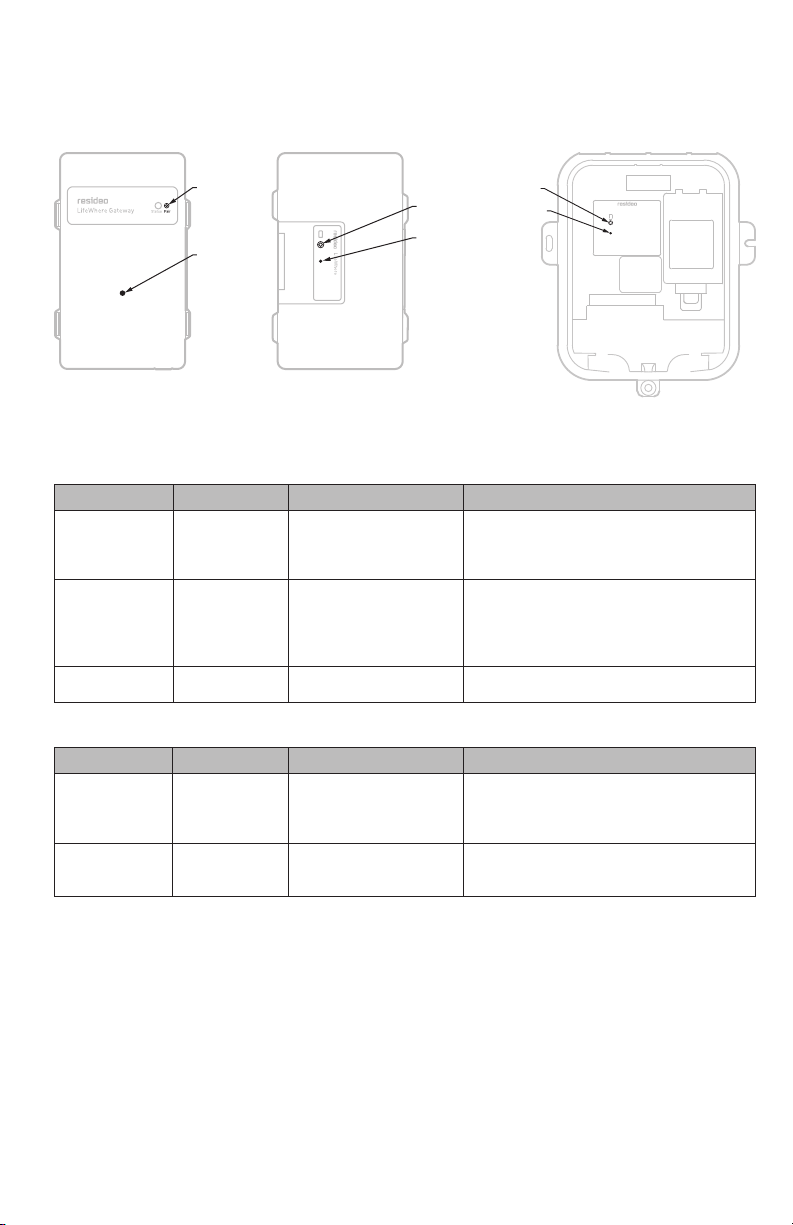
Gateway LED: Normal operation
Gateway LED Color/Status Description of Status Note
Yellow Blinking Wi-Fi is initializing either in AP (Access
Point) or Cloud Mode
Normal state during initial power
up
Pink Solid Gateway is not configured, AP (Access
Point) not active. Use Mobile App to
Configure
Normal state during initial power
up
Green Solid Wi-Fi is AP (Access Point) mode and can
be configured with Mobile App
Proceed with App Instructions
Cyan Solid Wi-Fi is waiting for communication from
server for time of day
N/A
Blue/Green Blinking ~30Sec Normal Operation, Sending Data to Cloud N/A
Blue Solid ~30Sec Normal Operation, Gateway is configured
and ready for cloud communications
Normal Standby Mode
Blue/Green Blinking ~3min+ Receiving Firmware update in progress
(3+min)
Wait for completion (back to solid
blue)
Blue/Pink Blinking ~1-2sec Normal Operation, Communicating with
Sensor Hub(s)
N/A
Blue/Pink Blinking ~1+ min Sending Firmware update to Sensor Hub
update in progress
Wait for completion (back to solid
blue)
Gateway LED: Error states
Gateway LED Color/Status Description Resolution
Blue Solid for ~120sec + (1)
or more Pink Blinks
WiFi Config is Correct and
connected to cloud. Configuration
is missing and/or incorrect
Put Gateway into AP Mode, Connect to
LifePulse Network, Reconfig Gateway for
Current # of Sensor Hubs
"Blue Solid for ~90sec + (1)
Green Blinks
Blue Solid for ~30sec + (1)
Pink Blinks"
Gateway is Communicating with
Sensor Hub(s), but not to Cloud.
This is normal on occasion, but if
this persists, reset is required
Reset Gateway by power cycle (Paperclip
Reset OR Unplug/Re-Plug in Outlet)
Blue Solid for ~120sec + (1)
Green Blinks
No Communication with Sensor
Hub
Paperclip reset on Sensor Hub
Red Solid Error Contact Customer Care at
1-855-LFWHERE
"Blue/Green Blinking for
~30sec
Blue Solid for ~30sec
Blue/Pink Blinking 3X
(repeat)"
Error connecting to user's Wi-Fi
after rebooting.
Check WiFi network status (up/down).
Check if WiFi SSID or password has
changed. If SSID/Password has changed,
put Gateway into AP mode and follow
in-app instructions to reset
Yellow Blinking for ~20 sec
+ Red Blink + White Bink
WiFi Network not discoverable. Check other WiFi devices for connection
to same network. Modem or Router may
be un-powered or resetting. If SSID or
p-word has changed, Re-Enter through in
App Instructions
Pink/Yellow Blinking, then
Solid Green
WiFi Password entered incorrectly
during initial setup
Follow in-app insturctions to re-enter
password

9 34-00048—03
Sensor Hub LED: Normal operation
Sensor Hub
ORANGE LED
Sensor Hub
RED LED
Description of Status Note/Resolution Applies to Indoor/
Outdoor Sensor
Hub
Blinking 1x/sec Off Sensor Hub Powered
and in Standby
Upon Battery Wakeup/
Initial Power, awiting
pairing
Indoor/Outdoor
Blinking 1x/sec Blinking
1-2x/2min
Sensor Hub Exchanging
Data with Gateway
Normal Operation Indoor/Outdoor
Blinking 1x/sec Rapid Blinking OTA Update in Progress Do Not Disconnect Indoor/Outdoor
Sensor Hub LED: Error states
Sensor Hub
ORANGE LED
Sensor Hub
RED LED
Description of Status Note/Resolution Applies to Indoor/
Outdoor Sensor
Hub
Solid Off Was configured to
Gateway, but currently
cannot connect
Gateway OTA Download in
Process (Blue/Green), Wait
for completion
–OR–
If Gateway in Standby
(Solid Blue) then reset
Gateway
Indoor/Outdoor
Off Solid Unconfigured to
Gateway
Add to Gateway
Configuration via Mobile
App
Indoor/Outdoor
Off Blinking 1x/
Sec
Low Battery Batteries may take time
to charge through several
AC runs
Outdoor
Off Off Initial Install Need to Run AC to
initialize/power up Sensor
Hub
Outdoor
Off Off Deep Sleep Occurs during off-season
(outdoor)
Outdoor

34-00048—03 10
Specifications
Gateway
Dimensions in in. (mm): 4.6 x 2.9 x 1.4 (117 x 74 x 36)
Weight in oz. (g): 3 (85)
Operational Temperature Range: 32°–104°F (0°–40°C)
Input Voltage: 5Vdc
Indoor Sensor Hub
Dimensions in in. (mm): 4.6 x 2.9 x 1.5 (117 x 74 x 38)
Weight in oz. (g): 5 (142)
Operational Temperature Range: -40°–158°F (-40°–70°C)
Input Voltage: 2.5–6.2Vdc
Outdoor Sensor Hub
Dimensions in in. (mm): 8.6 x 7.2 x 1.5 (218 x 183 x 38)
Weight in oz. (g): 5 (142)
Operational Temperature Range: -40°–158°F (-40°–70°C)
Input Voltage: 2.5–6.2Vdc
20A CT sensors
Dimensions in in. (mm): 48 x 1 x 1.6 (1219 x 25 x 41)
Weight in oz. (g): 2.5 (71)
Operational Temperature Range: -13°–158°F (-25°–70°C)
50A CT sensor
Dimensions in in. (mm): 72 x 1.6 x 2 (1829 x 41 x 51)
Weight in oz. (g): 2.5 (71)
Operational Temperature Range: -40°–158°F (-40°–70°C)
R & C Power Cable
Dimensions in in. (mm): 50 x 0.7 x 0.7 (1270 x 18 x 18)
Weight in oz. (g): 3 (85)
Operational Temperature Range: -40°–158°F (-40°–70°C)
Input Voltage: 24 Vac
Output Voltage: 5.5Vdc
Gateway Power Supply
Dimensions in in. (mm): 1.75 x 1.75 x 2 (45 x 45 x 51)
Weight in oz. (g): 2.5 (70)
Operational Temperature Range: 50°–158°F (10°–70°C)
Input Voltage: 100–240Vac
Output Voltage: 5Vdc

11 34-00048—03
Warranty
Resideo warrants this product, excluding battery, to be free from defects in workmanship or materials, under normal use and
service, for a period of two (2) years from the date of first purchase by the original purchaser. If at any time during the warranty
period the product is determined to be defective due to workmanship or materials, Resideo shall repair or replace it (at Resideo’s
option).
If the product is defective,
(i) return it, with a bill of sale or other dated proof of purchase, to the place from which you purchased it; or
(ii) call Resideo Customer Care at 1-800-633-3991. Customer Care will make the determination whether the product should be
returned to the following address: Resideo Return Goods, 1985 Douglas Dr. N., Golden Valley, MN 55422, or whether a replacement
product can be sent to you.
This warranty does not cover removal or reinstallation costs. This warranty shall not apply if it is shown by Resideo that the defect
was caused by damage which occurred while the product was in the possession of a consumer.
Resideo’s sole responsibility shall be to repair or replace the product within the terms stated above. RESIDEO SHALL NOT BE
LIABLE FOR ANY LOSS OR DAMAGE OF ANY KIND, INCLUDING ANY INCIDENTAL OR CONSEQUENTIAL DAMAGES RESULTING,
DIRECTLY OR INDIRECTLY, FROM ANY BREACH OF ANY WARRANTY, EXPRESS OR IMPLIED, OR ANY OTHER FAILURE OF THIS
PRODUCT.
Some states do not allow the exclusion or limitation of incidental or consequential damages, so this limitation may not apply to
you.
THIS WARRANTY IS THE ONLY EXPRESS WARRANTY RESIDEO MAKES ON THIS PRODUCT. THE DURATION OF ANY IMPLIED
WARRANTIES, INCLUDING THE WARRANTIES OF MERCHANTABILITY AND FITNESS FOR A PARTICULAR PURPOSE, IS HEREBY
LIMITED TO THE TWO YEAR DURATION OF THIS WARRANTY. Some states do not allow limitations on how long an implied
warranty lasts, so the above limitation may not apply to you.
This warranty gives you specific legal rights, and you may have other rights which vary from state to state. If you have any
questions concerning this warranty, please write Resideo Customer Care, 1985 Douglas Dr, Golden Valley, MN 55422 or call 1-800-
633-3991.

www.resideo.com
© 2020 Resideo Technologies, Inc. All rights reserved.
This product is manufactured by Resideo Technologies, Inc. and its affiliates.
Resideo Technologies, Inc.
1985 Douglas Drive North, Golden Valley, MN 55422
1-800-633-3991
34-00048—03 M.S. Rev. 11-20 | Printed in United States
CAUTION: EQUIPMENT DAMAGE HAZARD
Compressor protection is bypassed during testing. To prevent equipment damage, avoid cycling the compressor quickly.
CAUTION: ELECTRICAL HAZARD
Can cause electrical shock or equipment damage. Disconnect power before beginning installation.
Regulatory information
FCC REGULATIONS
§ 15.19 (a)(3)
This device complies with part 15 of the FCC Rules. Operation
is subject to the following two conditions:
1 This device may not cause harmful interference, and
2 This device must accept any interference received,
including interference that may cause undesired operation.
This equipment has been tested and found to comply with
the limits for a Class B digital device, pursuant to part 15
of the FCC Rules. These limits are designed to provide
reasonable protection against harmful interference in a
residential installation. This equipment generates, uses and
can radiate radio frequency energy, and if not installed and
used in accordance with the instructions, may cause harmful
interference to radio communications. However, there is
no guarantee that interference will not occur in a particular
installation. If this equipment does cause harmful interference
to radio or television reception, which can be determined by
turning the equipment OFF and ON, the user is encouraged to
try to correct the interference by one or more of the following
measures:
• Reorient or relocate the receiving antenna.
• Increase the separation between the equipment and
receiver.
• Connect the equipment into an outlet on a circuit different
from that to which the receiver is connected.
• Consult the dealer or an experienced radio/TV technician
for help.
IC REGULATIONS
RSS-GEN
This device complies with Industry Canada’s license-exempt
RSSs.
Operation is subject to the following two conditions:
1 This device may not cause interference; and
2 This device must accept any interference, including
interference that may cause undesired operation of the
device.
FCC Warning (Part 15.21) (USA only)
Changes or modifications not expressly approved by the party
responsible for compliance could void the user’s authority to
operate the equipment.
The product should not be disposed of with other household
waste. Check for the nearest authorized collection centers
or authorized recyclers. The correct disposal of end-of-life
equipment will help prevent potential negative consequences
for the environment and human health.
WEEE Disposal Notification
The product should not be disposed of with other
household waste. Check for the nearest authorized
collection centers or authorized recyclers. The correct
disposal of end-of-life equipment will help prevent
potential negative consequences for the environment
and human health.
Approvals
UL Classified under File SA45166 to UL 1995-2018 and
CAN-CSA C22.2 No. 236-15
This manual suits for next models
5
Table of contents