WV4262B POWERED DAMPER WATER HEATER CONTROLS
769-2496—05
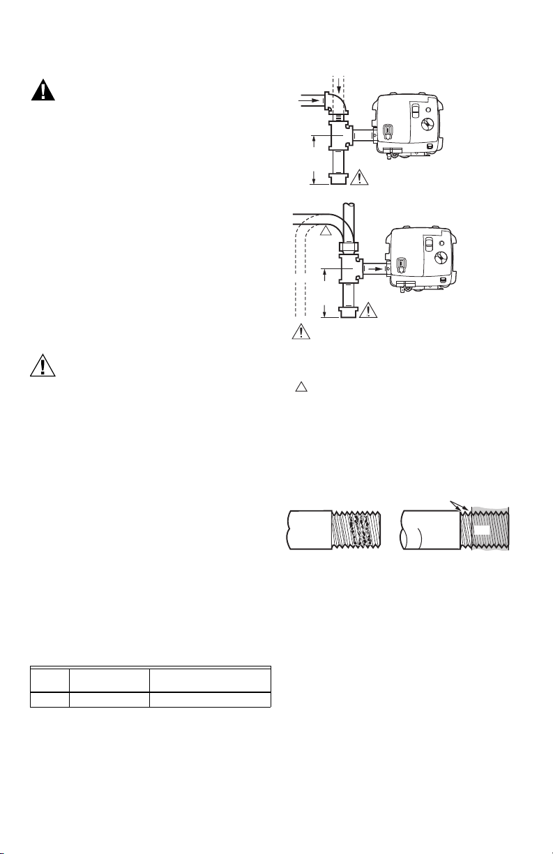
Gas Leak Test
1. Paint pipe connections upstream of the water
heater control with rich soap and water solution.
Bubbles indicate a gas leak.
2. If a leak is detected, tighten the pipe connections.
3. Stand clear of the burner while lighting to prevent
injury caused from hidden leaks that could cause
flashback in the appliance vestibule.
4. With the burner in operation, paint the pipe joints
(including adapters) and the control inlet and outlet
with rich soap and water solution.
5. If another leak is detected, tighten the adapter
screws, joints, and pipe connections.
6. Replace the part if a leak cannot be stopped.
Perform Gas Input and Burner
Ignition Check and Adjustment
Fire or Explosion Hazard
Can cause severe injury, death, or property damage.
Follow these warnings exactly:
1. Do not exceed input rating stamped on appliance
nameplate, or manufacturers recommended burner
orifice pressure for size orifice(s) used. Follow
instructions of appliance manufacturer.
2. IF CHECKING GAS INPUT BY CLOCKING GAS
METER: Make certain there is no gas flow through
the meter other than to the appliance being
checked. Other appliances must remain off with the
pilots extinguished (or that consumption must be
deducted from the meter reading). Convert flow rate
to Btuh as described in form 70-2602, Gas Controls
Handbook, and compare to Btuh input rating on
appliance nameplate.
3. IF CHECKING GAS INPUT WITH MANOMETER:
Make sure the manual gas shutoff switch is in the
OFF position before removing outlet pressure tap
plug to connect manometer (pressure gauge). Also
move the manual gas shutoff switch to the OFF
position when removing the gauge and replacing the
plug. Repeat Gas Leak Test at plug with main burner
operating.
Refer to the OS label on the Control for the pressure
reading, which should match the manometer
reading.
Gas Input and Burner Ignition Check
and Adjustment
1. Check the full rate manifold pressure listed on the
appliance nameplate. Water heater control full rate
outlet pressure should match this rating.
2. With burner operating, check the water heater
control flow rate using the meter clocking method
or check pressure using a manometer connected
to the outlet pressure tap on the water heater
control.
a. Meter Clocking: Convert flow rate to Btuh as
described in form 70-2602, Gas Controls Hand-
book, and compare to Btuh input rating on
appliance nameplate.
b. Manometer: Refer to the OS label on the Control
for the pressure reading, which should match
the manometer reading.
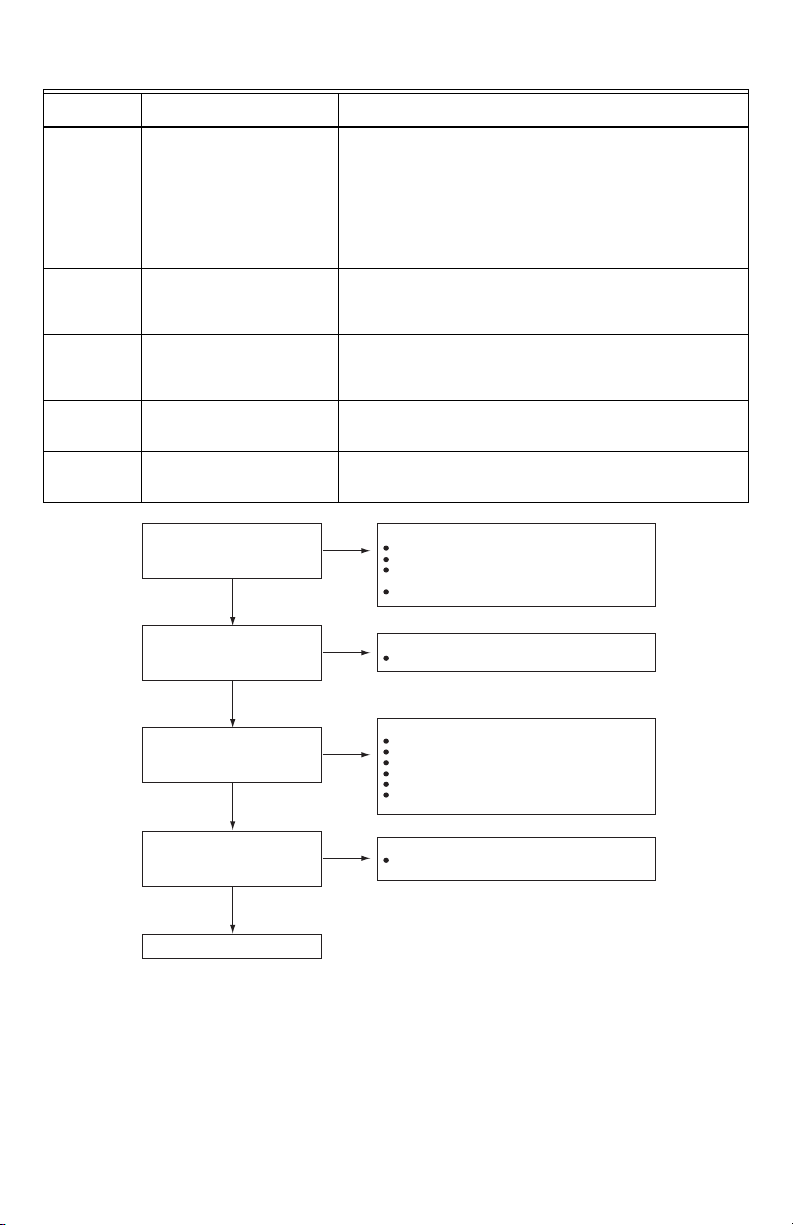
Perform Flame Current Check
1. Turn the temperature control knob to call for heat.
2. Observe the pilot burner during the ignition
sequence and see if:
a. Ignition spark continues after the pilot is lit.
b. The pilot lights and the spark stops, but main
burner does not light
c. The pilot lights, the spark stops, and main
burner light, but the system locks out.
3. If so, ensure adequate flame current as follows:
a. Turn off water heater at circuit breaker or fuse
box.
b. Clean the flame rod with emery cloth.
c. Make sure electrical connections are clean and
tight.
d. Check for cracked ceramic Insulator, which can
cause short to ground, and replace igniter--
sensor if necessary.
e. Check the pilot flame. Make sure it is blue,
steady, and envelops 3/8 to 1/2 in. (10 to 13
mm) of the flame rod.
4. After completing step 3, if any conditions in step 2
above recur, then replace the Control.