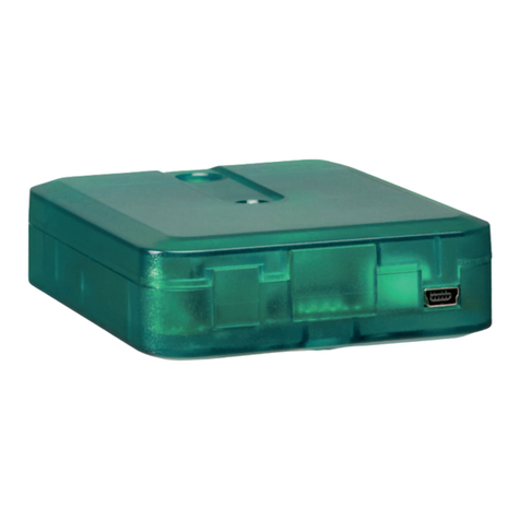
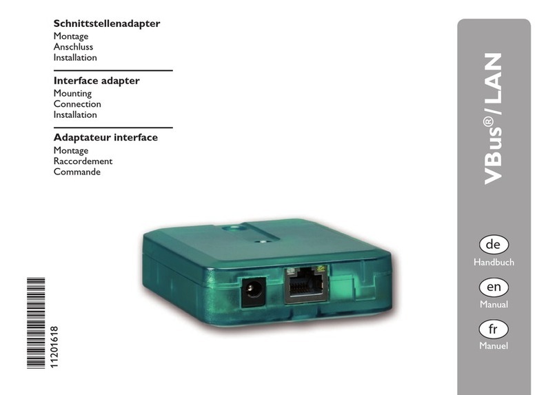
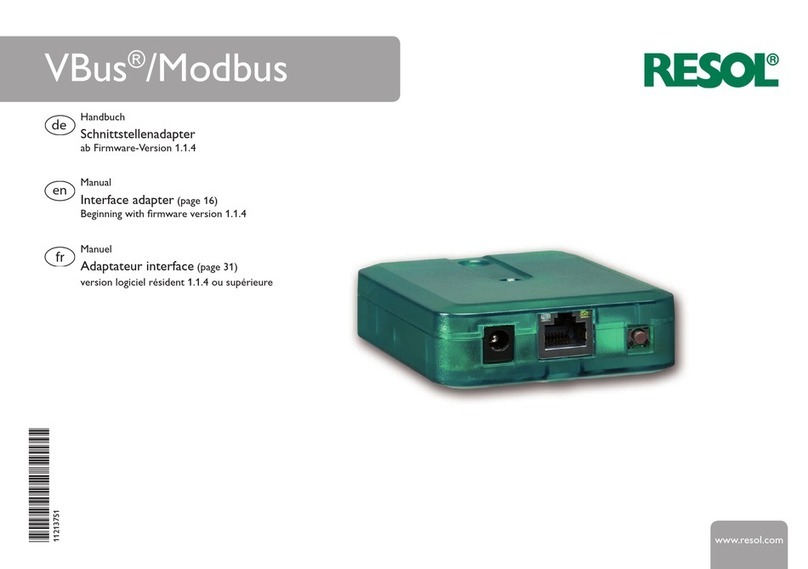
Resol Solar Manager Pro to LAN User manual

FB052 Kundenfreigabe:Anleitungen
Customer approval: Manuals
Ident.-Bezeichnung Ident. designation
Anleitung
Manual
Herausgabeindex:
Issue index:
erteilt am:
Date of approval:
Änderungsindex:
Change index:
Art.-Nr.:
Art. no.:
Unterschrift:
Signature:
ja /yes nein /no
Name in Druckbuchstaben:
Name in block letters:
Kundenfreigabe Customer approval
Format:
Format:
RESOL-Basis-Art.-Nr.:
Basic RESOL art. no.:
Datum:
Date:
Bearbeiter:
Issuer:
Bemerkungen:
Remarks:
Urheberrecht / Copyright
Das Copyright für die von der Firma RESOL –Elektronische Regelungen GmbH selbst erstellten Objekte, Dokumente, Grafiken,Abbildungen, Tondokumente,
Videosequenzen,Texte etc. bleibt allein bei der Firma RESOL. Eine Vervielfältigung, Weitergabe an Dritte, Veränderung der Inhalte oder die Verwendung in
elektronischen oder gedruckten Publikationen ist ohne ausdrückliche Zustimmung der Firma RESOL nicht gestattet.
Please note that RESOL – Elektronische Regelungen GmbH owns the sole copyright on objects, documents, graphics, pictures, audio and video documents, texts,
etc. published and created by RESOL – Elektronische Regelungen GmbH. Copying, distribution to third parties, changing the contents or using these contents in
electronic or printed publications is not permitted without the explicit approval by RESOL.
Ariston LAN
11206565
05.09.2014
A6Q
20140411
1.1
K. Erhardt

*11206565*
11206565
Solar Manager Pro
to LAN
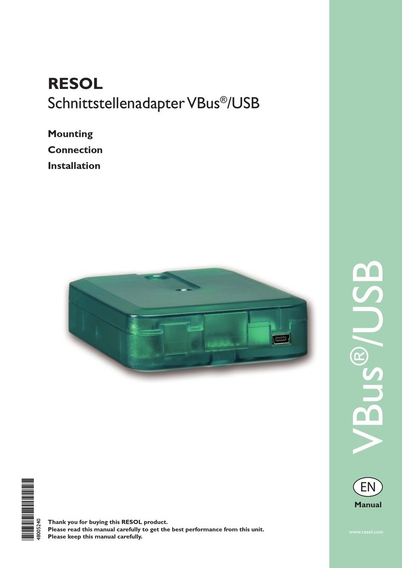
Interface adapter
Mounting
Connection
Installation
Adaptateur interface
Montage
Raccordement
Commande
Adaptador de interfaz
Montaje
Conexionado eléctrico
Instalación
Adattatore di interfaccia
Montaggio
Collegamento
Installazione
Manuel
fr
Manual
en
Manual
es
Manuale
it

en
2
Safety advice
Please pay attention to the following safety advice in order
to avoid danger and damage to people and property.
Description of symbols
ATTENTION! Warnings are indicated with a warning tri-
angle!
ÎThey contain information on how to
avoid the danger described.
Signal words describe the danger that may occur, when it
is not avoided.
• ATTENTION means that damage to the appliance can
occur.
• WARNING means that injury, possibly life-threatening
injury, can occur.
ÎArrows indicate instruction steps that should be car-
ried out.
Note
Notes are indicated with an information symbol.
Table of contents
1 Technical data................................................18
2 Mounting........................................................18
3 Electrical connection....................................19
4 Network settings ..........................................21
5 LED at the front of the housing...................26
6 Glossary .........................................................27
Thank you for buying this product.
Please read this manual carefully to get the best perfor-
mance from this unit.
Subject to change. Errors excepted.
© 20140905_11206565_VBus_LAN.mon4s.indd

en
3
Target group
These instructions are exclusively addressed to authorised
skilled personnel.
Only qualied electricians should carry out electrical
works. Initial installation must be effected by the system
owner or qualied personnel named by the system owner.
Instructions
Attention must be paid to the valid local standards, regula-
tions and directives!
Information about the product
Proper usage
The
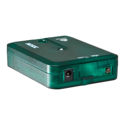
Solar Manager Pro to LAN
interface adapter may only
be used for connecting an electronic controller for solar
thermal systems to a computer network or PC via the
VBus® in compliance with the technical data specied in
these instructions.Improper use excludes all liability claims.
CE-Declaration of conformity
The product complies with the relevant directives
and is therefore labelled with the CE mark. The
Declaration of Conformity is available upon re-
quest, please contact the manufacturer.
Disposal
• Dispose of the packaging in an environmentally sound
manner.
• Dispose of old appliances in an environmentally sound
manner. Upon request we will take back your old appli-
ances bought from us and guarantee an environmentally
sound disposal of the devices.
Overview
• The network connection for your controller
• Access to the system via the complete network
• Remote parameterisation of the controller viaVBus®
• Full version of the RSC software included on CD-ROM
The
Solar Manager Pro to LAN
interface adapter is de-
signed for the connecting the controller directly to a PC or
router. It enables easy access to the controller via the local
network of the owner.
Thus, controller access, system parameterisation and data
charting can be effected from every workstation of the
network.
The
Solar Manager Pro to LAN
interface adapter is de-
signed for the connection to controllers equipped with a
VBus®.

en
4
1 Technical data
Housing: plastic
Protection type: IP 20 (EN 60529)
Ambient temperature: 0…40 °C
Dimensions: 95 × 70 × 25 mm
Mounting: wall mounting is possible (optional)
Display:
1 bi-coloured LED at the front of the housing
2 LEDs at the RJ45 LAN connection
Power supply:
mains adapter power supply: 100…240V~ /50-60 Hz
interface adapter power supply:12V�/ 0,5A 5.5 × 2.5 mm
Data interface:VBus®, LAN interface
Solar Manager Pro to LAN
Input: 12V / 0,5 A
5.5 x 2.5 mm -+
2 Mounting
The unit must only be located in dry interior rooms. It
is not suitable for installation in hazardous locations.The
interface adapter is light and small enough to not require
any form of mounting.It can be placed directly on the desk
or on a system component (pay attention to the allowed
ambient temperature!).
4 self-adhesive, skid-proof rubber pads are included with
the adapter. If necessary, these can be afxed to the corre-
sponding molds on the base part of the housing to ensure
a secure placement of the device without wall mounting.
If desired, the interface adapter can be mounted to a wall:
ÎMark the desired hanging position on the wall.
ÎDrill and prepare the hole with a wall plug and screw.
ÎHang the device onto the screw.
ÎMark the position for the mounting screw (centres
70 mm).
ÎDrill and prepare the hole with a wall plug.
ÎHang the device and fasten it by means of the second
screw.

en
5
Front view
Back view
Cover screw
Upper part of
the housing
Opening for
the mounting
screw
Molds for the
rubber pads
Hanging
Base part of
the housing
3 Electrical connection
ATTENTION!
ESD damage!
Electrostatic discharge can lead to damage
to electronic components!
ÎTake care to discharge properly be-
fore touching the inside of the device!
To do so, touch a grounded surface
such as a radiator or tap!
ATTENTION!
Short circuit!
A short circuit can lead to damage to elec-
tronic components!
ÎFinish terminal connection and close
the housing before establishing the
mains connection!
The Solar Manager Pro to LAN interface adapter needs a
mains, aVBus®and a LAN connection to function.To install
theVBus®cable, the housing has to be opened.
ÎTo open the housing, unscrew the cover screw and
pull off the upper part of the housing.
ÎConnect the includedVBus®cable to theVBus®termi-
nals with either polarity.
The VBus®cable can be extended or replaced with a two-
wire cable (bell wire).The cross section of the cable must
be at least 0.5mm2and the cable can be extended up to
50m in the case that one module is used.

en
6
ATTENTION!
Low voltage cables must not run together
in a cable conduit with cables carrying a
higher voltage than 50V.
ÎAlways route high and low voltage
cables separately!
ÎPay attention to the local regulations!
ÎClose the housing.
ÎTo close the housing again, relocate the upper part of
the housing and refasten the cover screw.
ÎEstablish the network connection by means of the in-
cluded LAN cable.
ÎEstablish the mains connection by means of the inclu-
ded mains adapter.
The Solar Manager Pro to LAN interface adapter is now
ready for normal operation.
Interior view of the Solar Manager Pro to LAN adapter
RJ45 LAN connector Mains connectorStatus-LEDs
Reset button
Bi-coloured
front-LED
VBus®terminals

en
7
4 Network settings
When UPnP access is activated, the operating system will
automatically recognise the Solar Manager Pro to LAN
interface adapter. Its IP address can then be seen in the
control panel.
Note
In MS Windows from version 7 on, UPnP access is
activated by default. In earlier versions, UPnP access
must be activated manually.
If the IP addresses in the local network are not assigned by
a DHCP server, proceed as follows:
ÎConnect the Solar Manager Pro to LAN interface
adapter directly to a PC.
The network settings of the PC used must be set to DHCP!
ÎCongure the Solar Manager Pro to LAN interface
adapter.
Finding the Solar Manager Pro to LAN interface
adapter in the local network
If the
Solar Manager Pro to LAN
interface adapter is not
recognised automatically, the DeviceDiscoveryTool soft-
ware on the CD-ROM enclosed can be used. In order to
use DeviceDiscovery, Java must be installed.
Web interface
All adjustments for the
Solar Manager Pro to LAN
interface
adapter can be made with the Web interface.
The Web interface is integrated in the
Solar Manager Pro
to LAN
interface adapter and can be run in an Internet
browser.
The Web interface has the following functions:
• Displaying the status of the Solar Manager Pro to LAN
interface adapter.
• Conguring the
Solar Manager Pro to LAN
interface
adapter.
• Adjusting the network settings of the
Solar Manager Pro
to LAN
interface adapter.
In order to access the Web interface, enter the IP address
of the
Solar Manager Pro to LAN
interface adapter into the
address bar of the browser.
The Web interface is not designed for controller access,
but for adjusting the network settings of the
Solar Manager
Pro to LAN
interface adapter.
When the Settings menu is selected, an authentication
enquiry will appear.
en
8
Enter the following credentials to authenticate:
User name: admin
Password: vbus
Note
In order to change the password, see page 8.
By means of the Settings menu of the Web interface, the
following settings can be adjusted:
• Assign a static IP address to the
Solar Manager Pro to
LAN
interface adapter.
• Change the name and the password of the
Solar Manager
Pro to LAN
interface adapter.
• Reset the
Solar Manager Pro to LAN
interface adapter.
• Select the menu language for the Web interface.
• Change the UPnP-port number.
• Change the MTU.
Changing the password
Note
The password is valid for the Web interface au-
thentication enquiry as well as for the access via
RSC/ RPT!
The default password for the authentication enquiry of the
Solar Manager Pro to LAN
interface adapter is vbus. It can
be changed in order to prevent unauthorised access.
To change the password, proceed as follows:
ÎClick on Settings in the Web interface.
ÎEnter the desired password into the VBus Password
input eld.
ÎClick on Update Settings.
The new password is saved.
Accessing the device is not possible without the correct
password.
ÎNote down the new password and keep it carefully!
If the password is lost,the device has to be reset to the fac-
tory settings. For more information see page 9.
Fig. 8
Changing the module name
In the same menu, a new module name can be assigned to
the
Solar Manager Pro to LAN
interface adapter.The device
will be displayed with its module name in the network.
ÎEnter the desired name into the Module Name in-
put eld.
ÎClick on Update Settings.
The new module name is saved.

en
9
Reset
If the password for the
Solar Manager Pro to LAN
interface
adapter is lost, the device has to be manually reset to the
factory settings. In order to conduct a reset, proceed as
follows:
ÎOpen the housing (see page 4).
ÎPress the reset button for 5s.
During the reset process, the front-LED ashes red.
As soon as the reset is completed, the LED switches to a
permanent red.
ÎAs soon as the LED switches to a permanent red, re-
lease the reset button!
ÎWhen the reset has been completed, close the hous-
ing (see page 4).
The reset will set the device back to factory settings. All
adjustments made in the Web interface (see page 7) will
be lost and will have to be made again.
Accessing the VBus®/LAN interface adapter over
the Internet
Note
The DeviceDiscoveryTool cannot be used for nding
a
Solar Manager Pro to LAN
interface adapter over
the Internet.
The following preparations have to be made when a
Solar
Manager Pro to LAN
interface adapter connected to the
Internet via a router is to be accessed over the Internet:
ÎAssign a static address to the router.
ÎCarry out port routing in the router.
Assigning a static router address
In order to access the router and the
Solar Manager Pro to
LAN
interface adapter connected over the Internet,a static
address has to be assigned to the router.
There are 2 different ways to assign a static Internet ad-
dress to the router:
• Over a dynamic Domain Name Server (DynDNS)
• Over a static Internet IP address

en
10
Using a dynamic Domain Name Server (DynDNS)
DynDNS address
+ Port
DynDNS
D
y
n
D
N
S
a
d
d
r
e
s
s
e
x
t
.
I
P
a
d
d
r
e
s
s
Port
Schematic representation: Remote access to the interface
adapter, router with DynDNS address.
Note
Not all routers support DynDNS services. For fu-
ther information consult the router documentation.
It is possible to reserve an Internet address via a DynDNS
service provider. DynDNS services are usually free of
charge.
Schematic process representation of using a DynDNS ad-
dress:
1. Open an account for a DynDNS Internet address at a
DynDNS service provider.A DynDNS Internet address
and the corresponding access information will be pro-
vided.
2. The DynDNS access information has to be entered into
the router, so that the router can tell the DynDNS ser-
vice provider where to route enquiries to.
3. In order to access the router via the Internet, the user
has to enter the DynDNS Internet address into the In-
ternet browser.
Using a static Internet IP address
Static IP address
+ Port
ISP
Static Internet IP
address
Port
Schematic representation: Remote access to the interface
adapter, router with static Internet IP address.
It is possible to apply for a static Internet IP address at an
Internet Service Provider (ISP).A fee is usually required for
a static IP address.
Schematic process representation of using a static IP ad-
dress:
1. Apply for a static IP address at an Internet Service
Provider (ISP). A static Internet address and the corre-
sponding access information will be provided.
2. The access information has to be entered into the rout-
er, so that the router can register with the ISP using the
static IP address.

en
11
3. The router registers at the ISP with the static IP address.
4. In order to access the router via the Internet, the user
has to enter the static Internet address into the Internet
browser.
Port routing in the router
Note
Not all routers support port routing. For futher in-
formation consult the router documentation.
In order to access, over the Internet, one or several inter-
face adapters connected to one router, port routing has to
be congured in the router.
The
Solar Manager Pro to LAN
interface adapter commu-
nicates via the following ports:
• Web interface port: 443 (adjustable, default port: 443)
• ServiceCenter port: 7053 (non-adjustable)
In order to carry out port routing in the router, proceed
as follows:
ÎAssign a static LAN IP address to the
Solar Manager
Pro to LAN
interface adapter using the conguration
menu of the router.
ÎAssign a port to the IP address menu using the con-
guration menu of the router.
In this example (see table), 3 interface adapters are as-
signed 1 web interface port and 1 ServiceCenter software
port each.
Example: Port routing
Device number DynDNS address Port routing from port: Port routing to port: LAN IP
1 www.vbuslan.ath.cx:443 443 443 192.168.0.10
2 www.vbuslan.ath.cx:444 444 443 192.168.0.11
3 www.vbuslan.ath.cx:445 445 443 192.168.0.12
1 www.vbuslan.ath.cx:7053 7053 7053 192.168.0.10
2 www.vbuslan.ath.cx:7054 7054 7053 192.168.0.11
3 www.vbuslan.ath.cx:7055 7055 7053 192.168.0.12

en
12
5 LED at the front of the housing
The
Solar Manager Pro to LAN
interface adapter has 1 bi-
coloured LED at the front of the housing and 2 LEDs at the
RJ45 LAN connector.
The bi-coloured LED at the front of the housing indicates
the current operating status of the
Solar Manager Pro to
LAN
interface adapter:
LEDashesgreen:
Adapter is booting
LED is permanently green:
Normal operation, access is now possible
Static IP address/IP address obtained from a DHCP server
LEDslowlyashesgreen:
Normal operation, access is now possible
IP address has been generated by the device
LEDirregularlyashesgreen:
Normal operation, data trafc
LEDashesred/green:
No network connection / IP address lost
LEDquicklyashesred:
Reset in progress
LED is permanently red:
Reset completed
Status LEDs at the RJ45 LAN connector
At the RJ45 LAN connector there are 2 status LEDs which
indicate the status of the network connection:
10/100 Link/Activity LED:
LED glows: Network connection ok, no data trafc
LED ashes irregularly: data trafc
Full duplex LED:
LED glows: Full duplex active
10/100 Link/Activity LED Full duplex LED

en
13
© All contents of this document are protected by copyright.

fr
14
Sommaire
2 Caractéristiques techniques .......................32
1 Montage .........................................................32
3 Branchement électrique ..............................33
4 Installation dans le réseau............................35
5 LED sur la partie supérieure du boîtier......40
6 Glossaire ........................................................41
Nous vous remercions d’avoir acheté cet appareil.
Veuillez lire ce manuel attentivement an de pouvoir utiliser
l’appareil de manière optimale.
Sousréserved’erreursetdemodicationstechniques.
© 20140905_11206565_VBus_LAN.mon4s.indd
Recommandations de sécurité
Veuillez lire attentivement les recommandations de sécu-
rité suivantes an d’éviter tout dommage aux personnes
et aux biens.
Explication des symboles
ATTENTION !
Les messages d’avertissement sont pré-
cédés d’un triangle de signalisation !
ÎIls indiquent comment éviter les
dangers !
Certains termes utilisés dans ce mode d’emploi vous aver-
tissent des dangers potentiels auxquels vous vous exposez
en cas de non respect des consignes de sécurité énoncées.
• Attention indique une situation susceptible de provo-
quer des dommages matériels.
• Avertissement indique que de graves dommages cor-
porels, voire même un danger de mort peuvent survenir.
ÎLes paragraphes précédés d’une èche contraignent
l’utilisateur à agir sur l’appareil.
Note
Toute information importante communiquée à l’uti-
lisateur est précédée de ce symbole.

fr
15
Personnes concernées
Ce manuel d’instructions vise exclusivement les techni-
ciens habilités.Toute opération électrotechnique doit être
effectuée par un technicien en électrotechnique.
Instructions
Pour toute opération relative à l’appareil,veuillez respecter
les normes, réglementations et directives en vigueur!
Informations concernant l’appareil
Utilisation conforme
L’adaptateur Solar Manager Pro to LAN doit s’utiliser
uniquement comme dispositif de liaison entre un appareil
doté duVBus®et un réseau informatique en tenant compte
des données techniques énoncées dans le présent mode
d’emploi.
Toute utilisation non conforme entraînera une exclusion
de la garantie.
Déclaration de conformité CE
Le marquage „CE“ est apposé sur ce produit,
celui-ci étant conforme aux dispositions commu-
nautaires prévoyant son apposition. La déclara-
tion de conformité de la société est disponible
sur demande.
Traitement des déchets
• Veuillez recycler l’emballage de l’appareil.
• Les appareils en n de vie doivent être déposés auprès
d’une déchèterie ou d’une collecte spéciale de déchets
d’équipements électriques et électroniques. Sur de-
mande, nous reprenons les appareils usagés que vous
avez achetés chez nous en garantissant une élimination
respectueuse de l’environnement.
Vue d’ensemble
• Dispositif de connexion du régulateur au réseau
• Accès aux données de l’installation depuis le réseau
• Conguration à distance du régulateur à travers le VBus®
• CD avec logiciel RSC (version complète) inclus
L’adaptateur Solar Manager Pro to LAN constitue l’inter-
face entre le régulateur et l’ordinateur ou le routeur, et
permet ainsi d’avoir accès au régulateur à travers le réseau
local de l’utilisateur, de congurer l’installation et d’établir
le bilan des données enregistrées depuis n’importe quelle
station connectée au réseau.
L’adaptateur interface Solar Manager Pro to LAN peut se
connecter à tous les régulateurs dotés d’unVBus®.

fr
16
1 Montage
Réalisez le montage de l’appareil dans une pièce intérieure
sèche. Grâce à la taille réduite de l’appareil, il n’est pas
nécessaire de l’accrocher au mur. Celui-ci peut tout sim-
plement être posé sur une surface appropriée (veillez à
respecter la température ambiante autorisée !)
L’adaptateur est livré avec quatre pieds antidérapants au-
toadhésifs en caoutchouc. Ceux-ci peuvent être collés sur
les cavités prévues à cet effet au dos de l’appareil an de
pouvoir le xer sur une surface plate.
Si vous souhaitez accrocher l’adaptateur interface au mur,
réalisez les opérations suivantes:
ÎMarquez le point d’accrochage sur le mur ou la paroi,
percez et introduisez la cheville et la vis dans le trou
correspondant.
ÎAccrochez le boîtier à la vis supérieure et marquez
le point de xation inférieur (distance entre les deux
trous : 70 mm).
ÎPercez le mur ou la paroi et introduisez la cheville et
la vis dans le trou correspondant.
ÎAccrochez le boîtier à la vis supérieure et xez-le au
mur avec la vis inférieure.
2 Caractéristiques techniques
Boîtier : en plastique
Type de protection : IP 20 (EN 60529)
Température ambiante : 0…40 °C
Dimensions : 95 × 70 × 25 mm
Montage : montage mural (facultatif)
Afchage:
1 LED bicolore sur la partie supérieure du boîtier
2 LED sur le connecteur RJ45 LAN
Alimentation :
Tension d’entrée de l’adaptateur secteur :
100… 240V~ /50-60 Hz
Tension d’entrée de l’adaptateur interface :
12V �/ 0,5 A 5.5 × 2.5 mm
Interface :VBus®, RJ45 LAN
Solar Manager Pro to LAN
Input: 12V / 0,5 A
5.5 x 2.5 mm -+

fr
17
3 Branchement électrique
ATTENTION !
Décharges électrostatiques !
Des décharges électrostatiques peuvent en-
dommager les composants électroniques !
ÎDéchargez-vous de l’électricité statique !
ATTENTION !
Court-circuit !
Des décharges électrostatiques peuvent en-
dommager les composants électroniques !
ÎBranchez tous les câbles de l’adapta-
teur et refermez le boîtier de ce der-
nier avant de le brancher sur une prise
électrique !
Pour fonctionner correctement, l’adaptateur interface re-
quiert une connexion secteur,une connexionVBus®et une
connexion LAN. Pour brancher le câbleVBus®sur l’adapta-
teur, ouvrez le boîtier.
ÎPour ouvrir le boîtier, dévissez la vis de fermeture et
détachez la partie supérieure de celui-ci.
ÎBranchez le câble VBus®sur les deux bornes VBus®
sans tenir compte de leur polarité.
Le câble VBus®peut se rallonger à l’aide d’un simple câble
biliaire courant (l de sonnerie). La section du câble doit
être au moins égale à 0,5mm2. Le câble peut être rallongé
jusqu’à 50m lorsque l´adaptateur n´est connecté qu’à un
seul appareil.
vue de face
vue de dos
vis de fermeture
partie supérieure
du boîtier
orice pour la
vis de xation
pieds antidé-
rapants en
caoutchouc
oeillet de
suspension
partie inférieure
du boîtier

fr
18
Vue intérieure de l’adaptateur Solar Manager Pro to LAN
connecteur RJ45
pour le câble LAN
connecteur
pour l’adapta-
teur secteur
LED d’indication
de l’état fonction-
nement
touche reset
LED bico-
lore sur le
devant du
boîtier
bornesVBus®
ATTENTION ! L’installation de câbles basse tension et de
câbles trasmettant une tension supérieure
à 50 V dans un même caniveau risque
d’endommager l’appareil.
ÎInstallez les câbles basse tension et
les câbles de branchement électrique
séparemment !
ÎRespectez les directives concernées
en vigueur !
ÎRefermez le boîtier.
ÎPour ce faire, placez la partie supérieure du boîter sur
la partie inférieure et vissez la vis de fermeture.
ÎEtablissez la connexion réseau avec le câble LAN
(inclus dans la fourniture).
ÎEtablissez la connexion au réseau en utilisant l’adapta-
teur secteur (inclus dans la fourniture).
L’adaptateur interface Solar Manager Pro to LAN est, à
présent, prêt à l’emploi.

fr
19
4 Installation dans le réseau
Lorsque l’accès UPnP est activé, le système d’exploitation
reconnaît l’adaptateur interface Solar Manager Pro to LAN
automatiquement ; l’adresse IP est indiquée sur le panneau
de conguration.
Note
Dans les systèmes d’exploitation Windows 7 ou
supérieur, l’accès UPnP est activé par défaut. Dans
les versions plus anciennes, il doit s’activer manuel-
lement.
Si les adresses IP n’ont pas été fournies par un serveur
DHCP, effectuez les opérations suivantes :
ÎConnectez l’adaptateur interface VBus®/LAN directe-
ment à un ordinateur.
Les connexions réseau de l’ordinateur doivent être réglées
sur DHCP !
ÎCongurez l’adaptateur interface VBus®/LAN.
Chercher l’adaptateur interface Solar Manager Pro
to LAN dans le réseau
Si l’adaptateur interface Solar Manager Pro to LAN n’est
pas reconnu automatiquement, utilisez l’outil DeviceDiso-
veryTool du CD-ROM fourni avec l’appareil.Le DeviceDis-
coveryTool, ne fonctionne que si Java est installé.
Interface Web
L’adaptateur interface Solar Manager Pro to LAN se con-
gure sur l’interfaceWeb.
L’interface Web est intégrée dans l’adaptateur interface et
s’exécute dans un navigateur Internet.
L’interface permet d’effectuer les fonctions suivantes :
• Indiquer l’état de fonctionnement de l’adaptateur interface.
• Congurer l’adaptateur interface.
• Connecter l’adaptateur interface au réseau.
Pour accéder à l’interface Web, saisissez l’adresse IP de
l’adaptateur interface Solar Manager Pro to LAN sur la
ligne d’adresse du navigateur internet.
L’interface Web n’est pas conçue pour permettre d’accé-
der au régulateur mais pour connecter l’adaptateur inter-
face Solar Manager Pro to LAN au réseau.
Lorsque vous sélectionnez le menu Réglages, une de-
mande d’authentication s’afche.
L’authentication requiert les données suivantes :
Nom d’utilisateur: admin
Mot de passe: vbus
Note
Pour changer le mot de passe, voir page 20.
Table of contents
Languages:
Other Resol Adapter manuals

Resol
Resol VBus/CANopen User manual

Resol
Resol VBus/Modbus User manual

Resol
Resol VBus/PWM User manual

Resol
Resol Vbus/LAN User manual

Resol
Resol VBus/EnOcean Interface adapter User manual

Resol
Resol VBus User manual

Resol
Resol VBus/PWM User manual

Resol
Resol Vbus/LAN User manual

Resol
Resol VBus/USB User manual
Popular Adapter manuals by other brands

D-Link
D-Link PowerLine DHP-302 Quick installation guide

NETGEAR
NETGEAR PowerLINE 1000 Series user manual

CMP
CMP A2F100 installation instructions

3idee
3idee acr-hy Assembly instructions

Linksys
Linksys PCMLM56 - EtherFast - 56 Kbps Network Specifications

Comtrend Corporation
Comtrend Corporation PowerGrid 9142s Quick installation guide