Resol DeltaSol MiniPool User manual

www.resol.com
RESOL D e lt a S o l® MiniPool
Mounting
Connection
Operation
D e lt a S o l® MiniPool
EN
Manual
*48004880*
48004880
Thank you for buying this RESOL product.
Please read this manual carefully to get the best performance from this unit.
Please keep this manual carefully.

Subject to technical change. Errors excepted.
Table of contents
General information .................................................2
1. Overview ..............................................................3
2. Installation ............................................................4
2.1 Mounting ........................................................................ 4
2.2 Electrical connection .................................................. 5
3. Basic system .........................................................6
4. Operation and function ......................................7
4.1 Push buttons ................................................................. 7
4.2 Operational concept ................................................... 7
5. Status display ....................................................... 8
6. Menu structure .................................................... 9
6.1 Display values ............................................................. 12
6.2 Balance values ............................................................. 13
6.3 Functions / Adjustments ........................................... 13
7. Functions and options ....................................... 10
8. Error indication .................................................12
9. Troubleshooting .................................................13
10. Accessories .........................................................14
Imprint ..................................................................... 16
Subject to technical change. Errors excepted.
Description of symbols
Disposal
Signal words describe the danger that may occur, when it
is not avoided.
Warning means that injury, possibly life-threatening injury,
can occur.
Attention means that damage to the appliance can occur.
•Dispose of the packaging in an environmentally sound
manner.
•Dispose of old appliances in an environmentally sound
manner. Upon request we will take back your old
appliances bought from us and guarantee an environ-
mentally sound disposal of the devices.
Information about the product
Proper usage
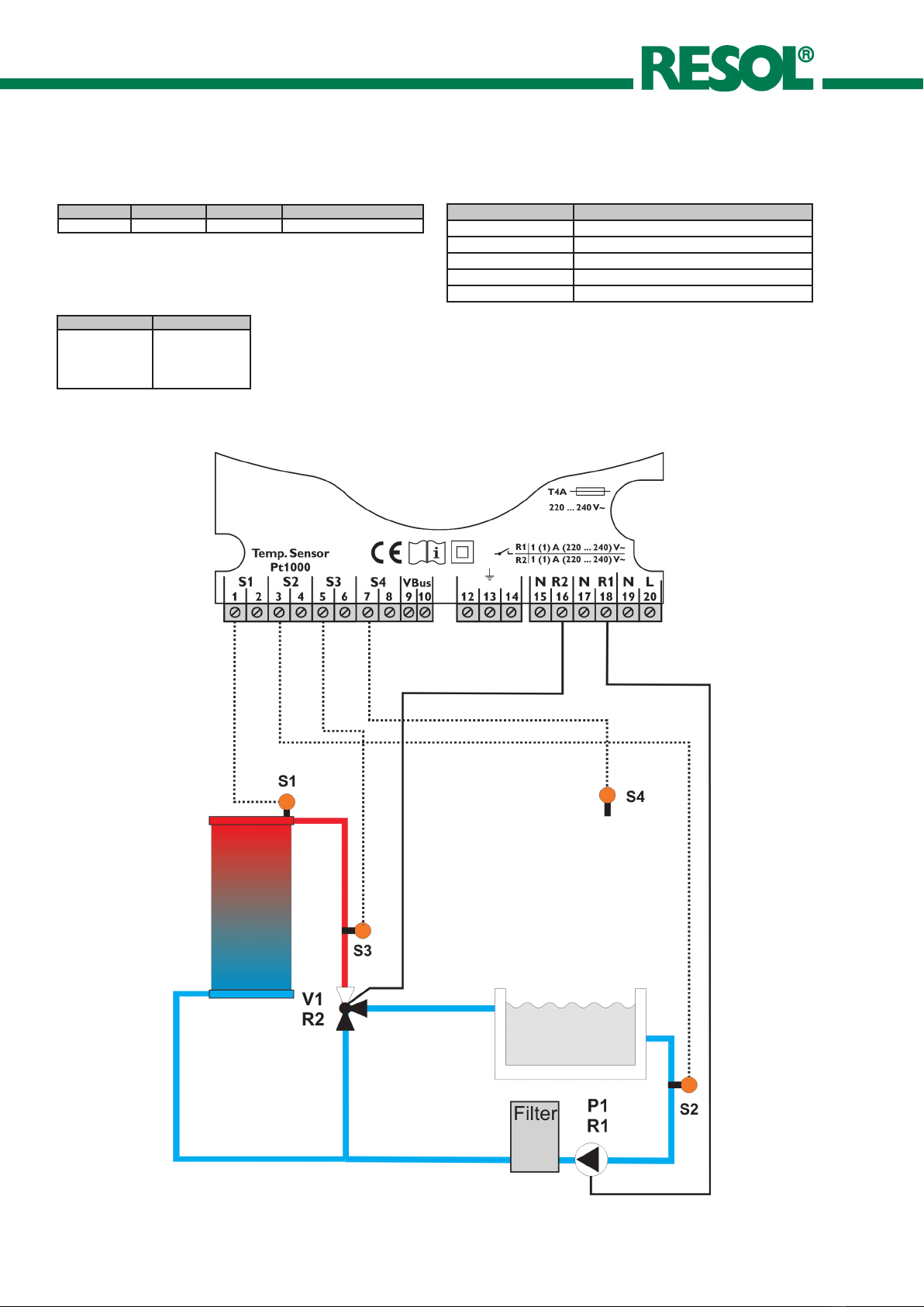
The RESOL D e l t a S o l® MiniPool is to be used for heating
a swimming pool by means of solar collectors and optimised
operation of the filter system in compliance with the technical
data specified in this manual.
Improper use excludes all liability claims.
CE-Declaration of conformity
The product complies with the relevant
directives and is therefore labelled with the
CE mark. The Declaration of Conformity
is available upon request, please contact
RESOL.
Note
Notes are indicated with an information symbol.
ÎArrows indicate instruction steps that should be
carried out.
Safety advice
Please pay attention to the following safety advice in order
to avoid danger and damage to people and property.
Instructions
Attention must be paid to the valid local standards, regu-
lations and directives!
This manual contains important information about safe and
proper usage of this product. Please keep this manual for
future reference.
Target group
These instructions are exclusively addressed to authorised
skilled personnel.
•Only qualified electricians should carry out electrical
works.
•Initial installation must be effected by qualified personnel
named by the manufacturer
Note
Strong electromagnetic fields can impair the
function of the controller.
ÎMake sure the controller as well as the
system are not exposed to strong electro-
magnetic fields.
WARNING! Warnings are indicated with a
warning triangle!
ÎThey contain information
on how to avoid the danger
described.
D e lt a S o l® MiniPool
© RESOL 09225 DeltaSol_MiniPool.monen.indd
| 2

• Controller for heating a swimming pool by means of solar collectors and
optimised operation of the filter system.
• Solar operating hours counter and heat quantity balancing
• 4 sensor inputs
• 2 relay outputs
• Function control
• RESOL VBus®
Included:
1 x D e l t a S o l® MiniPool
1 x accessory bag
1 x spare fuse T1,25A
2 x screws and wall plugs
4 x strain relief and screws
Additionally included with the full kit:
1 x FKP6 sensor
2 x FRP6 sensor
Technical data
Housing: plastic, PC-ABS and PMMA
Protection type: IP 20 / DIN 40 050
Ambient temperature: 0 ... 40 °C
Dimensions: 172 x 110 x 49 mm
Mounting: wall mounting, mounting
into patch panels is possible
Display:
graphic display, 160 x 64 px
Operation: 3 push buttons at the
front
Functions: controller for heating a
swimming pool by means of solar ab-
sorbers in combination with the opti-
mised operation of the filter system.
Solar loading:
When the absorber temperature is by
an adjusted value higher than the pool
temperature, solar loading starts. If
the difference between flow and pool
falls below a certain value, or if the
maximum temperature is reached, solar
loading is stopped.
Sensor inputs: 4 inputs for Pt1000
sensors
Relay outputs: 2 relay outputs
Bus: RESOL VBus®
Power supply: 220 … 240 V~
Total switching capacity:
4 (1) A (220 … 240) V~
Rated impulse voltage: 2,5 kV
Mode of operation: type 1.B
Switching capacities:
2 (1) A (220 … 240) V~
(standard relay)
1. Overview
D e lt a S o l® MiniPool
© RESOL 09225 DeltaSol_MiniPool.monen.indd
3 |

display
push button
cover
can fuse T1,25A
cable conduits with strain relief
2.1 Mounting
The unit must only be located in dry interior rooms. It is not
suitable for installation in hazardous locations and should
be protected against electromagnetic fields. The controller
must additionally be supplied from a double pole switch with
contact gap of at least 3 mm. Please pay attention to separate
routing of sensor cables and mains cables.
ÎUnscrew the crosshead screw from the cover.
ÎPull the cover downwards to remove it from the
housing.
ÎMark the upper fastening point on the wall, drill and
fasten the enclosed wall plug and screw leaving the
head protruding.
ÎHang the housing from the upper fastening point and
mark the lower fastening point through the hole in the
terminal box (centres 130 mm). Drill and insert the
lower wall plug
ÎFasten the housing to the wall with lower fastening
screw and tighten.
ÎCarry out the electrical connections according to the
specifications.
ÎRefasten the cover.
2. Installation
upper fastening
lower fastening
WARNING! Electric shock!
Opening the housing will expose
live parts!
ÎSwitch off power supply and dis-
connect the device from mains
before opening the housing!
ATTENTION! ESD damage!
Electrostatic discharge can lead to da-
mage to electronic components!
ÎTake care to discharge properly
before touching the inside of the
device!
D e lt a S o l® MiniPool
© RESOL 09225 DeltaSol_MiniPool.monen.indd
| 4

2.2 Electrical connection
2.2.1 Overview of electrical connections
The controller is equipped with two relays to which loads
can be connected:
• Relays R1 and R2 are electromechanical relays:
R1 and R2 = conductor R1 ... R2
N = neutral conductor N
(common terminal block)
PE = protective conductor PE
(common terminal block)
Depending on the product version, mains cable and sensor
cables are already connected to the device. If that is not the
case, please proceed as follows:
Connect the temperature sensors (S1 to S4) to the
corresponding terminals with either polarity.
Connect the mains cable to the following terminals:
19 = neutral conductor N
20 = conductor L
12 = protective conductor
12
S1 S2 S3
3456
Te mp . Sensor
Pt1000
L N R1 N R2 N
20 19 18 17 16 15
S4
78 14 13 12
DeltaSol Minipool
220 ... 240 V~
VBus
9 10
2 (1) A ( 220 ... 24 0) V ~
T1,25A
Connecting the device to the power supply must always be
the last step of the installation!
The power supply of the device must be 220 ... 240 V~
(50 ... 60 Hz).
2.2.2 Data communication / Bus
The controller is equipped with the RESOL VBus® for data
transfer with and energy supply to external modules. The
connection is carried out at the two terminals marked “VBus”
(either polarity). One or more RESOL VBus® modules can be
connected via this data bus:
•RESOL DL2 Datalogger
•RESOL GA3 Large Display
•RESOL SD3 Smart Display
•RESOL STA-W kWh output module
•RESOL VBus®/USB Interface adapter
12
S1 S2 S3
3456
Te mp . Sensor
Pt1000
L N R1 N R2 N
20 19 18 17 16 15
S4
78 14 13 12
DeltaSol Minipool
220 ... 240 V~
VBus
9 10
2 (1) A ( 220 ... 24 0) V ~
T1,25A
VBus® terminals
D e lt a S o l® MiniPool
© RESOL 09225 DeltaSol_MiniPool.monen.indd
5 |

3. Basic system
Relay allocation
Sensor allocation
S1 S2 S3 S4
Tabsorber Tpool Tflow T - freely selectable
R1 R2
Filter pump P1 3-way valve V1
Solar: on/off
Sensor Description
Tabsorber Absorber temperature
Tpool Pool temperature
Tflow Flow temperature
S4 freely selectable; with WMZ Treturn
Treturn Return temperature
Sensor abbreviations
D e lt a S o l® MiniPool
© RESOL 09225 DeltaSol_MiniPool.monen.indd
| 6

3
4. Operation and function
4.1 Push buttons The controller is operated via the three push buttons be-
low the display. The forward-button (1) is used for scrolling
forward through the menu or to increase the adjustment
values. The backward-button (2) is similarly used for scrolling
backwards and reducing values. Button 3 is used for selec-
tion of the menu lines and for confirmation.
1
2
4.2 Operational concept Adjustment mode
In the adjustment mode, different functions can be selected
and values can be adjusted.
ÎTo access the adjustment mode, scroll down past the
last adjustment channel and press button 1 for approx.
three seconds.
ÎSelect the desired value or function by pressing buttons
1 and 2, then confirm by pressing button 3
Adjusting values:
ÎSelect the value by pressing buttons 1 or 2, then briefly
press button 3; the adjustment range is displayed in the
form of a bar.
ÎAdjust the desired value by pressing buttons 1 and 2; this
value is shown on the bar by means of a slider.
ÎBriefly press button 3 to confirm the adjustment.
ÎPress button 3 again to store the adjustment. The con-
troller will then go back to the adjustment menu.
If button 3 is not pressed after the adjustment, the display
will go back after a few seconds. The adjustment will not
be stored.
Selecting a function or option:
ÎSelect the desired function or option by pressing but-
tons 1 and 2, then briefly press button 3.
ÎSelect Yes to activate the selected function, or select
No to deactivate the function.
ÎBriefly press button 3 to confirm the selection.
ÎPress button 3 again to store the adjustment.
ÎAn activated function is indicated by means of a marked
checkbox. Additionally, the corresponding adjustment
values are displayed.
No
Yes
Minimum filter runtime:
Minimum filter runtime
Filtration period 1 h
Filter ending time 12:00
Adjustments:
x
40
10
28 °C
Poolmax.
ÎIn order to leave the adjustment mode and get back to
the display mode, keep button 2 pressed until the first
menu item of the main menu is reached.
ÎThen briefly press button 2 to get back to the display
mode.
If no button is pressed for two minutes, the controller will
automatically go back to the status display.
backwards forward
SET
(selection / adjustment mode)
D e lt a S o l® MiniPool
© RESOL 09225 DeltaSol_MiniPool.monen.indd
7 |

5. Status display In the status display, the operating status of the system is
indicated:
Solar: on: Solar loading is active
Solar: off: Solar loading is inactive
Cooling: Cooling is active, pool temperature is dis-
played
Filtration: Filter pump is active; the remaining time is
displayed
Additionally, possible causes for the Solar: on and Solar:
off status of the system are indicated:
Pool Max.: Maximum pool temperature is reached
Flow Max.: Maximum flow temperature is reached
Abs. max.: Maximum absorber temperature is reached
Abs. min.: Minimum absorber temperature is reached
Sensor failure
Min. On: Minimum runtime is active
Min. Off: Minimum break time is active
D e lt a S o l® MiniPool
© RESOL 09225 DeltaSol_MiniPool.monen.indd
| 8

6.1 Display values
The following values are displayed:
Display Description
TAbsorber Absorber temperature in °C
Tpool Pool temperature in °C
Tflow Flow temperature in °C
Sensor4 Temperature at an additional
sensor location
6.2. Balance values
The following values can be charted:
Display Description
Max. TAbs. Maximum absorber temperature
Min. TAbs. Minimum absorber temperature
Max. Tpool Maximum pool temperature
Min. Tpool Minimum pool temperature
Max. Tflow Maximum flow temperature
Min. Tflow Minimum flow temperature
Display Description
Max. Sensor4 Maximum outdoor temperature
Min. Sensor4 Minimum outdoor temperature
oper. days Number of operating days of the
controller
oper. hours R1 Operating hours of the filter pump
(P1 at R1)
oper. hours R2 Solar loading operating hours
(V1 at R2)
Display Description
time Time
Filter runtime Present-day runtime of the filter
pump
Relay1 Relay1 on / off
Relay2 Relay2 on / off
6.3 Functions / Adjustment values
Display Description
DTon Switch-on difference
DToff Switch-off difference
poolmax Maximum pool temperature
T-DTon Delay
mIN on Minimum runtime
mIN off Minimum break time
time Time
Minimum filter runtime Minimum filter runtime
circulation Circulation function
flowMAX. Maximum flow limitation
aBSORBERmax. Absorber maximum limitation
aBSORBERMIN. Absorber minimum limitation
poolcooling Pool cooling
6. Menu structure
For more detailed information about the functions and the
corresponding adjustment values see ch. 7 “Functions and
options“.
D e lt a S o l® MiniPool
© RESOL 09225 DeltaSol_MiniPool.monen.indd
9 |

7. Functions and options
Adjustment of the minimum runtime in minutes.
The minimum time for which the solar system remains swit-
ched on after the switch-on conditions have been fulfilled.
The minimum runtime is not aborted by the maximum pool
temperature limitation.
Adjustment of the minimum break time in minutes.
The period of time for which the solar system remains
switched off after the switch-off condition has been ful-
filled.
Minimum runtime
Adjustments/Min on
Adjustment range: 0 ... 10 min
Factory setting: 2 min
Minimum break time
Adjustments/Min off
Adjustment range: 0 ... 10 min
Factory setting: 2 min
Maximum pool temperature
Adjustments/poolmax.
Adjustment range: 10 ... 40 °C
Factory setting: 28 °C
Adjustment of the maximum pool temperature in °C.
When the adjusted maximum pool temperature is reached,
the solar system switches off. The circulation function is
not inhibited.
Switch-on difference
Adjustments/DTon
Adjustment range: 0.2 ... 25.0 K
Factory setting: 2.5 K
Switch-off difference
Adjustments/DToff
Adjustment range: 0.0 ... 24.8 K
Factory setting: 0.3 K
Adjustment of the switch-on difference (TAbsorber - TPool)
for the solar circuit in Kelvin.
Adjustment of the switch-off difference (TFlow - TPool) for
the solar circuit in Kelvin. The switch-off difference has to
be at least 0.2 K lower than the switch-on difference DTon.
Adjustment of the minimum filter pump runtime in hours.
The filter pump is switched on for this adjusted filtration
period every day.
The filter runtime ends when the adjusted ending time is
reached.
The minimum filter runtime will also be complied with in
the case of a sensor failure.
Example: With a filter runtime of 4 hours, the filter pump
has to be continuously active from 16:00 o‘clock
on in order to reach the adjusted runtime be-
fore the adjusted ending time at 20:00 o‘clock is
reached.
Minimum filter runtime
Adjustments/minimum filter runtime
Selection: “Yes”, “No”
Factory setting: “No”
Adjustments/filtration period
Adjustment range: 0 ... 16 h
Factory setting: 5 h
Adjustments/ending time
Adjustment range: 00:00 ... 23:30
Factory setting: 20:00
Switch-on delay
Adjustments/t-DTon
Adjustment range: 00:01 ... 10:00
Factory setting: 01:00
Adjustment of the switch-on delay t-DTon. The switch-on
conditions must be fulfilled for this period of time for the
solar loading to start.
ÎFirst adjust the minutes and confirm the adjustment
ÎThen adjust the seconds and confirm the adjustment
Adjustment of the current time
Time
Adjustments/time
D e lt a S o l® MiniPool
© RESOL 09225 DeltaSol_MiniPool.monen.indd
| 10

Circulation function
Adjustments/circulation
Selection: “Yes”, “No”
Factory setting: “No”
Adjustments/Starting time
Adjustment range: 00:00 ... 23:45
Factory setting: 07:00
Adjustments/stopping time
Adjustment range: 00:15 ... 24:00
Factory setting: 20:00
Adjustments/period
Adjustment range: 1 ... 10 min
Factory setting: 1 min
If the solar system has not been active for the period of one
hour, it will be switched on for 1 ... 10 minutes (Flushing the
pipes with pool water in order to measure the pool tem-
perature during a system standstill).
Start / end of the circulation period (time).
Adjustment of the circulation duration in minutes.
Absorber maximum limitation
Adjustments/Absorbermax.
Selection: “Yes”, “No”
Factory setting: “No”
Adjustments/TAbs.max.
Adjustment range: 60 ... 160 °C
Factory setting: 130 °C
Adjustments /DTAbs.max.
Adjustment range: 2 ... 50 K
Factory setting: 10 K
The absorber maximum limitation inhibits solar loading
from the absorber if the adjusted temperature threshold
(TAbs.max.) is exceeded.
Adjustable switch-on and switch-off hysteresis (DTAbs.max.)
which prevents the controller from switching on and off
again because of very small temperature differences.
Absorber minimum limitation
Adjustments/Absorbermin.
Selection: “Yes”, “No”
Factory setting: “No”
Adjustments/TAbs.Min.
Adjustment range: 10 ... 90 °C
Factory setting: 10 °C
Adjustments/DTAbs.min.
Adjustment range: 0.3 ... 10 K
Factory setting: 2.0 K
This function ensures that a solar loading is only effected if
a given absorber temperature is exceeded.
Adjustable switch-on and switch-off hysteresis (DTAbs.min.)
which prevents the controller from switching on and off
again because of very small temperature differences.
Flow maximum limitation
Adjustments/flowmax.
Selection: “Yes”, “No”
Factory setting: “Yes”
Adjustments/Tflowmax.
Adjustment range: 30 ... 100 °C
Factory setting: 40 °C
Adjustment of the flow maximum limitation.
If this function is active, solar loading will be switched off
when the maximum flow temperature is exceeded (scald
protection).
D e lt a S o l® MiniPool
© RESOL 09225 DeltaSol_MiniPool.monen.indd
11 |

Pool cooling function
Adjustments/poolcooling
Selection: “Yes”, “No”
Factory setting: “No”
Experte/Adjustments/DTcool
Adjustment range: 0.3 ... 10.0 K
Factory setting: 2.0 K
Experte/Adjustments/DTcoolon
Adjustment range: 0.3 ... 10.0 K
Factory setting: 3.0 K
Experte/Adjustments/DTcooloff
Adjustment range: 0.2 ... 10.0 K
Factory setting: 1.5 K
If the maximum pool temperature is exceeded by a certain
value (DTcool), this function cools the pool by discharging
heat through the absorber. This is only possible if the ab-
sorber is cooler than the pool by the adjusted temperature
difference DTcoolon.
Cooling is switched off when the value DTcooloff is reached
or when Poolmax. is underrun.
The adjustable minimum difference between switch-on and
switch-off temperature (hysteresis) prevents the controller
from switching on and off again due to very small tempera-
ture differences..
Manual operation
Manual operation/Relay1 (2)
Selection: “Off”, “On”, “Auto”
Factory setting: “Auto”
Each relay can be set into the Off / On / Auto mode. During
normal operation, the relay is set to Auto.
Language
language
Selection: “Deutsch”, “English”, “francais”, “castellano”,
“italiano”
Factory setting: “Deutsch”
Adjustment of the menu language: Deutsch, English, fran-
cais, castellano, italiano.
8. Error indication A possible failure of the pool-, flow- or absorber sensor will
be indicated on the display. The solar system will be switched
off or, if already off, remain inactive. In the case of a failure
of the outdoor temperature sensor, the system will not be
switched off or kept inactive.
Adjustment of the sensor offset.
A sensor offset can be carried out (-5 K ... +5 K, adjustment
step size 0.1 K).
Sensors
Sensor Offset
Sensor1 (2, 3, 4)
Heat quantity balancing
Adjustments/heat quantity
Selection:“Yes”, “No”
Factory setting: “No”
Adjustments/flow rate
Adjustment range: 0.1 ... 500 l/min
Factory setting: 5 l/min
Heat quantity balancing is possible if a flowmeter is used.
The flow rate should be read from the window of the
flow setter at 100 % pump speed and must be adjusted as
flow rate.
Note
For heat quantity balancing, S4 has to be used
for measuring the return temperature (see
chap. 3).
D e lt a S o l® MiniPool
© RESOL 09225 DeltaSol_MiniPool.monen.indd
| 12

9. Troubleshooting
can fuse T1,25A If a malfunction occurs, a message is displayed in the display
of the controller:
12
S1 S2 S3
3456
Te mp . Sensor
Pt1000
L N R1 N R2 N
20 19 18 17 16 15
S4
78 14 13 12
DeltaSol Minipool
220 ... 240 V~
VBus
9 10
2 (1) A ( 220 ... 24 0) V ~
T1,25A
Operating control lamp off.
Check the power supply. Is it disconnected?
yesno
The fuse of the controller
could be blown. It can be
replaced after the front
cover has been removed
(spare fuse is enclosed in
the accessory bag).
Check the supply line and
reconnect it.
D e lt a S o l® MiniPool
© RESOL 09225 DeltaSol_MiniPool.monen.indd
13 |

10. Accessories
Overvoltage protection device
In order to avoid overvoltage damage at absorber sensors
(e.g. caused by local lightning storms), we recommend in-
stalling the overvoltage protection RESOL SP10.
Sensors
Our product range includes high-precision platin tempe-
rature sensors, flatscrew sensors, outdoor temperature
sensors, indoor temperature sensors, cylindrical clip-on
sensors and irradiation sensors, also as complete sensors
with immersion sleeves.
RESOL ServiceCenter Software
The controller data can be read out for visualising and mo-
nitoring the system state. The light version of the software
is availabe for free download at www.resol.com.
The full version additionally allows easy configuration of the
control parameters with a PC.
D e lt a S o l® MiniPool
© RESOL 09225 DeltaSol_MiniPool.monen.indd
| 14

Notes
D e lt a S o l® MiniPool
© RESOL 09225 DeltaSol_MiniPool.monen.indd
15 |

Distributed by:
Please note:
The design and the specifications are to be changed without notice.
The illustrations may differ from the original product.
RESOL - Elektronische Regelungen GmbH
Heiskampstraße 10
45527 Hattingen / Germany
Tel.: +49 (0) 23 24 / 96 48 - 0
Fax: +49 (0) 23 24 / 96 48 - 755
www.resol.com
info@resol.com
Reprinting / copying
This mounting- and operation manual including all parts is
copyrighted. Another use outside the copyright requires
the approval of RESOL - Elektronische Regelungen GmbH.
This especially applies for copies, translations, microfilms
and the storage into electronic systems.
Editor: RESOL - Elektronische Regelungen GmbH
Important notice:
We took a lot of care with the texts and drawings of this
manual and to the best of our knowledge and consent. As
faults can never be excluded, please note: Your own calcu-
lations and plans, under consideration of the current stan-
dards and guidelines should only be basis for your projects.
We don´t offer a guarantee for the completeness of the
drawings and texts of this manual - they only represent
some examples. They can only be used at your own risk.
No liability is assumed for incorrect, incomplete or false
information and / or the resulting damages.
D e lt a S o l® MiniPool
© RESOL 09225 DeltaSol_MiniPool.monen.indd
| 16
Other manuals for DeltaSol MiniPool
1
Table of contents