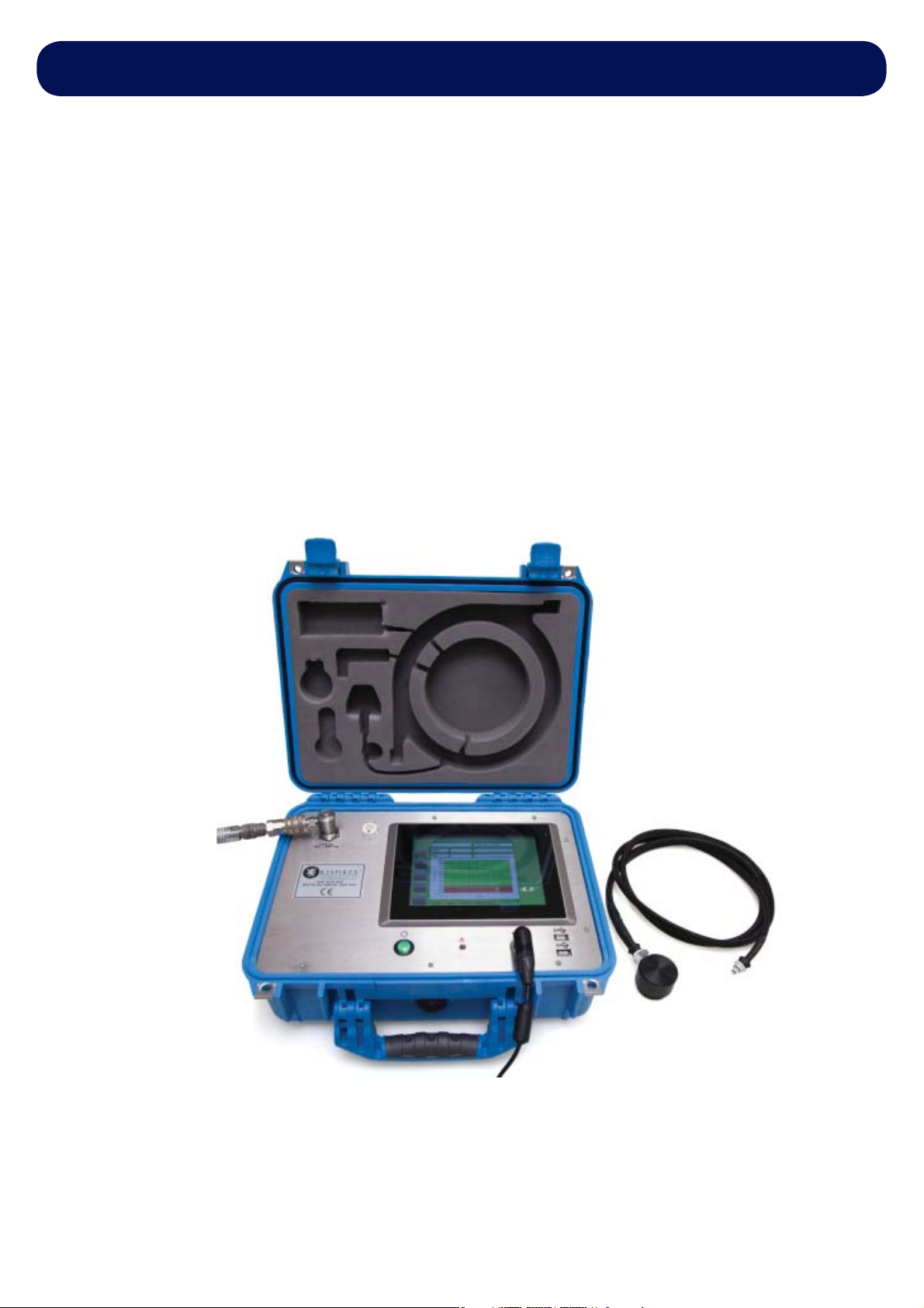
Respirex AUTOMATIC TEST BOX User manual

Gas-Tight Suit
Automatic Test Unit
ENGLISH
BS\097\A\2015

Contents
Essential information................ ...............................................................1
Electricity supply........................................................................................1
Fuses (UK & Ireland Only)................ .......................................................1
Method of use.............................................................................................2
Care and maintenance................ ............................................................3
Specications..............................................................................................3
EC Declaration of conformity................................................................3

Gas-tight chemical protective clothing is worn in
combination with appropriate respiratory protective
devices in order to isolate the body of the wearer from the
environment. Although a danger to the wearer arises from
leakage in an inward direction, the EN 464 test method
assesses the outward leakage of air after the gas-tight suit
has been inated. This stretches the material of construction
enabling the detection of very small imperfections, e.g.
holes, splits or tears.
The digital automatic test unit is designed specically for
determining the leak-tightness of Respirex gas-tight suits to
the European standard EN943 using the EN 464 ination test
method. The unit has been designed to be easy to use and as
such the operation of the unit is largely intuitive
On opening the test unit case the user will see that the lid
contains:
• 12 volt dc power supply
• Mains lead to the power supply
• Braided hose to connect the test unit to the suit
• Suit adaptor to connect the braided hose to an
exhalation valve that has been opened and had its
diaphragm removed
• Rubber bung with which to seal o the remaining
exhalation valve from the inside of the suit during the
test
The test unit control panel comprises:
• A rotating air inlet with CEJN tting to be connected
to either a compressed airline supply or an optional
electrical air pump which can be supplied with the test
unit
• A 12 volt power-in socket
• A socket to take the braided hose that connects the test
unit to the suit under test
• An illuminated on/o rocker switch
• A touch-screen computer
• A red over-pressure warning light (this light illuminates
briey on start-up to conrm that it is functioning
correctly)
• Two USB ports to which the user may connect:
o A mouse (not supplied)
o A keyboard (not supplied)
o A USB memory-stick (not supplied)
Please note: It is not possible to connect a USB printer to the
test unit.
When operating the test unit please follow the instructions in
this manual carefully.
Essential information
Do not install the test unit in the following locations.
• A hot or humid location (near a water tap, hot water
heater, humidier, heater air conditioner or other
appliance that generates heat) or a cold and dry
location.
• A location which is exposed to direct sunlight (if
necessary shut out light with a curtain)
• A poorly ventilated location.
• A dusty location.
• A location where ammonia gas is emitted.
• In the vicinity of a volatile inammable substance such
as alcohol or paint thinners.
• A location which is subjected to strong vibrations.
• A location subject to abrupt changes in temperature.
By rapidly raising the temperature of a cold location
water droplets (condensation) will form on the inside
of the test unit which may result in damage to sensitive
components.
Note : The test unit is designed solely for indoor use.
If the red over-pressure warning light illuminates during use
the test box should be switched-o. The user should check
that the ination hose is not kinked and that it is connected
to both the test unit and the suit adaptor correctly. The unit
should then be re-started and the test recommenced. If,
during the recommenced test the warning light illuminates
again the unit should be switched o and the manufacturer
should be contacted.
Electricity supply
The test unit should be connected via the 12v dc power
supply via a suitable switched socket in an accessible
position.
Fuses (UK & Ireland Only)
The mains lead to the test unit power supply is tted with a
plug and a 5A fuse. If the fuse requires replacing only those
rated at 5A and ASTA approved to BS1362 should be used.
Correct replacement is identied by colour coding and/or
marking on the base of the plug.
CE marking certies that this appliance complies
with requirements laid down in EEC Directive 89:336
(Electromagnetic compatibility).
ENGLISH
1

ENGLISH
2
Method of use
Prior to performing the internal pressure test, lay out the
gas-tight suit including gloves and boots and full face mask
if appropriate, on a suitable at and clean surface away
from any sources of heat and/or currents of air. Remove any
creases and folds from the suit as far as practicable. Leave the
suit for a minimum of 1 hour at ambient temperature (20 ±
5)°C.
1. Insert the mains lead into the 12v power supply and
plug into an appropriate AC mains electricity supply.
2. Plug the right-angled connector from the 12v power
supply into the socket marked ‘12v DC’ on the control
panel.
3. Connect a clean compressed air source set between 1 -
3.5 Bar (100-350 kPa) max. to the rotating inlet located
at the top left hand corner of the control panel.
4. Using a torque driver with a ‘T8’ Torx bit, loosen and
remove the screw from the centre of one of the suit
exhalation valves, then remove the cap.
5. Carefully slide the diaphragm up the central spigot and
remove from the exhalation valve body.
6. Push the suit adaptor fully into the exhalation valve
body.
7. Seal o any remaining valves on the inside of the suit
using the rubber bungs provided and ensure that the
suit zipper is fully closed.
8. Plug one end of the ination hose into the white
socket on the control panel and the opposite end into
the white socket on the suit adaptor plugged into the
exhalation valve.
9. Turn on the test unit using the green rocker switch
located at the bottom of the control panel (a green light
will illuminate in the switch). The red over-pressure
warning light will illuminate briey and the test unit
computer will boot up into the Respirex testing screen.
10. Press ‘Start’ on the touchscreen computer; the test unit
will commence inating the gas-tight suit, the display
background with turn mauve and ‘INFLATING’ will be
indicated.
11. The test unit will stop ination at the required pressure;
the display background with turn amber, a 10 minute
timer will begin and ‘SETTLING’ will be indicated.
During the 10 minute settling period the test unit may
inject short bursts of air to maintain pressure within the
gas-tight suit.
12. After completion of the settling period the display
background will turn brown and indicate ‘DEFLATING’.
The test unit will allow the gas-tight suit to deate
until the required pressure for the start of the internal
pressure test is reached (1650 Pa).
13. Once the required pressure for the start of the
internal pressure test is reached (1650Pa) the display
background will turn blue; a black trace line will start
to appear from the horizontal line marked 1650Pa on
the display graph and a 6 minute timer will begin. The
black trace line will remain active whilst the test timer
is in operation. Note: Each vertical line on the display
graph indicates 1 minute of elapsed time.
14. After 6 minutes the black trace line will stop and the
nal pressure within the suit will be frozen on the
display. If the pressure reading on the display is above
1350Pa the gas-tight suit has passed the test and the
display background will turn green. If the nal pressure
is below this gure the suit has failed the test and
the display background will turn red. The date and
time, nal pressure in Pascals and result (PASS or FAIL)
are automatically displayed in the relevant elds on
the screen. The user may input information of their
choice into the remaining elds on the screen (Title,
Operator, Location, Suit No. and Notes) using either the
touchscreen keyboard or alternatively a USB keyboard
connected via one of the ports at the lower right hand
corner of the control panel.
15. If required, the nal test may be saved on the computer
by pressing ‘Save’ on the touchscreen, browsing to a
le location of your choice and selecting and suitable
lename. Previous test results can be reloaded to the
display screen by pressing ‘Load’ and browsing to the
relevant le.
16. If a permanent record of the test is required for viewing
or printing on a remote computer an image le can
be saved to a portable USB drive inserted in one of
the ports at the lower right hand corner of the control
panel. Press ‘Save’ on the touchscreen, wait a short
period for the save as box to appear, browse to the
drive letter of the inserted USB drive, choose a lename
and press save. The USB drive can now be removed and
inserted into a remote computer where the image le
can be saved as a backup of the test result, viewed and
printed.
17. After completion of the internal pressure test press
‘Shut Down’ on the touchscreen, allow the computer to
shut down fully then switch o the green illuminated
rocker switch.

3
ENGLISH
18. Disconnect the ination hose from the suit adaptor
attached to the exhalation valve; remove the suit
adaptor from the exhalation valve and check that
there is no dust, debris or contamination of any kind
in the exhalation valve body. Carefully slide a new
diaphragm down the central spigot until it rests evenly
on the valve body. Ensure the diaphragm is correctly
orientated with the ridged side uppermost. Replace
the exhalation valve cap and ensure the two location
channels engage with the locating keys on either side
of the valve body. Note: When correctly located, the
valve cap will not rotate independently on the valve
body. Replace the centre screw, turn by hand two times
to engage the thread with the valve body, then fully
tighten using a torque driver set to 23 ± 2 cN.
19. Open the suit zip and remove all rubber bungs from
any remaining exhalation valves. If required, additional
bungs may be purchased from Respirex, please quote
part no. D00702.
20. Disconnect the opposite end of the ination hose from
the white socket on the control panel.
21. Unplug the right-angled connector from the socket
marked ‘12v DC’; remove the mains lead from the 12v
power supply and unplug from AC mains electricity
supply.
WARNING : If spraying gas-tight suits to locate leaks under no
circumstances allow water to enter the test unit.
Care and maintenance
Under NO circumstances use water or abrasive substances to
clean the test unit. The outer surfaces of the unit should be
wiped with a dry cloth only.
Occasionally it is advisable to inspect the rubber‘O’ring tted
to the suit adaptor for signs of wear. If necessary a new ‘O’
ring can be purchased from Respirex.
If themainslead becomesdamagedcontactthe manufacturer
or an authorised service agent for a replacement part.
The test unit is designed to be maintenance free; there are
no user serviceable parts contained in the test unit. In the
event of malfunction, disconnect from the electricity supply
and check the 5A fuse tted to the mains lead plug (UK and
Ireland only). If the fuse is in good working order and the test
unit still fails to operate please contact Respirex International
Ltd or an authorised agent for further assistance.
Respirex recommend that all packaging supplied with the
automatic test unit is retained for the purpose of returning
the unit to the manufacturer or authorised service agent for
service.
Tel : +44 (0)1737 778600
Fax: +44 (0)1737 779441
Specications
POWER SOURCE AC 240V,50Hz, 100mA
POWER CONSUMPTION Approx. 24W maximum
when inating
DIMENSIONS 433 x 177 x 279.4mm (W x H x D)
17 x 7 x 11” (W x H x D)
WEIGHT Approx. 9.7 kg (21.4lb)
EC Declaration of conformity
This is to certify that the:
Gas Tight Suit Automatic Test Unit, Model No. G02500 series
Manufactured by:
Respirex International Ltd,
Unit F Kingseld Business Centre,
Philanthropic Road,
Redhill, Surrey RH1 4DP. UK
Conforms with the protection requirements of Council
Directive 2004/108/EC, relating to Electromagnetic
Compatibility, and Council Directive 2006/95/EC, relating to
the Low Voltage Directive, by the application of:
EN 61326-1: Electrical equipment for measurement, control
and laboratory use — EMC requirements — Part 1: General
requirements (unit conforms to both basic requirements and
industrial requirements).
EN61010: Safety Requirements for Electrical Equipment
for measurement, control & laboratory use. (Part 1 General
Requirements).
Signed: ................................................
Position: Managing Director
Of: Respirex International Ltd
Date: October 2015

RESPIREX INTERNATIONAL LTD,
Unit F Kingseld Business Centre,
Philanthropic Road,
Redhill,
Surrey RH1 4DP
United Kingdom
Tel. +44 (0) 1737 778600
Table of contents