Ecraft ECT-CCTV071 User manual
For more information call:
NSW: ARTARMON Unit 3, 6-8 Mclachlan Ave, Ph: 02-9438-3266 Fax: 02-9438-2924
KINGSGROVE Unit E3, 15 Forrester Rd, Ph: 02-9150-6033 Fax: 02-9150-6044
BLACKTOWN Unit 1, 36 Binney Rd Ph: 02-8811-5155 Fax: 02-9831-2139
WA: BELMONT Unit 2, 28 Belmont Avenue, Ph: 08-9478-6411 Fax: 08-9478-6422
QLD: NERANG Unit 13, 12-20 Lawrence Drive, Ph: 07-5596-5533 Fax: 07-5596-5194
Schmidt and Muller Telecommunications Pty Ltd trading as ELECTROCRAFT AUSTRALIA - ABN 79 067 000 426
CCTVTESTER
User Manual
(V01.00)
ECT-CCTV071

Thank you for purchasing the IP camera tester. Please read the manual before using the IP camera
tester and use properly.
For using the IP camera tester safely, please first read the「Safety Information」carefully in the
manual.
The manual should be kept well in case of reference.
Keep the S/N label for after-sale service within warranty period. Product without S/N label will
be charged for repair service.
If there is any question or problem while using the IP camera tester, or damages occurred on the
product, please contact our technical Department.
Schmidt and Muller Telecommunications Pty Ltd trading as ELECTROCRAFT AUSTRALIA - ABN 79 067 000 426

Content
1 .Safety information
...............................................................................................................................
1
2. IP Camera Tester Introduction
.............................................................................................................
2
2.1 General
......................................................................................................................................
2
2.2
Packing list
................................................................................................................................
3
2.3
Function interface
......................................................................................................................
4
3. Operation
.............................................................................................................................................
7
3.1 Installing the Battery
..................................................................................................................
7
3.2
Instrument connection
................................................................................................................
8
3.2.1 IP camera connection
......................................................................................................
8
3.2.2 Analog camera connection
..............................................................................................
9
3.2.3 HD Coaxial camera connection
.....................................................................................
10
3.2.4 HDMI IN.......................................................................................................................
10
3.2.5
HDMI output
.................................................................................................................
11
3.3 OSD menu
...............................................................................................................................
11
3.3.1 Drop-down Menu
..........................................................................................................
11
3.3.2 Short cut-menu
..............................................................................................................
12
3.3.3 Screen capture
...............................................................................................................
13
3.3.4 Link monitor
.................................................................................................................
13
3.3.5 TesterPlay
.....................................................................................................................
15
3.3.6 IP discovery
..................................................................................................................
16
3.3.7 IPC Test pro
..................................................................................................................
17
3.3.8 Rapid ONVIF test
.........................................................................................................
18
3.3.9 NON
ONVIF
.................................................................................................................
30
3.3.10 HDMI IN ( *Optional )
...............................................................................................
32
3.3.11 Analog camera test
......................................................................................................
35
3.3.12 Color-bar generator (TV OUT)
...................................................................................
43
Schmidt and Muller Telecommunications Pty Ltd trading as ELECTROCRAFT AUSTRALIA - ABN 79 067 000 426

3.3.13 AutoHD ( *Optional )
.................................................................................................
44
3.3.14 HD Coaxial & Analog level test ( *Optional )
.............................................................
44
3.3.15 SDI Camera Test (
*Optional )
.................................................................................
46
3.3.16 CVI camera test ( *Optional )
...................................................................................
47
3.3.17 TVI camera test ( *Optional )
...................................................................................
54
3.3.18 AHD camera test ( *Optional )
.................................................................................
56
3.3.19 NET TOOL PRO.........................................................................................................
57
(1)IP address scan
.............................................................................................................
57
(2)PING Test
....................................................................................................................
58
(3)Network test (Ethernet bandwidth test)
........................................................................
58
(4)Port Flashing
................................................................................................................
61
(5)DHCP server
................................................................................................................
62
(6)Trace route
...................................................................................................................
63
(7)Link monitor
................................................................................................................
63
3.3.20 PoE power / DC12V 3A and DC 5V 2A USB power output
.......................................
64
3.3.21 DC 24V 2A power output............................................................................................
65
3.3.22 Cable Test
...................................................................................................................
66
3.3.23
RJ45 cable TDR test
....................................................................................................
67
3.3.24 Cable Tracer
( *Optional )
........................................................................................
69
3.3.25 TDR cable test ( *Optional )
.....................................................................................
71
3.3.26 BNC attenuation test ( *Optional )
..............................................................................
74
3.3.27 PoE Voltage test
..........................................................................................................
75
3.3.28 12V power input test
...................................................................................................
76
3.3.29 Digital
Multi-meter
( *Optional )
.............................................................................
77
3.3.30 Optical power meter ( *Optional )
............................................................................
85
3.3.31 Visual Fault Locator ( *Optional )
............................................................................
87
3.3.32 Audio Record
..............................................................................................................
88
3.3.33 Data monitor
...............................................................................................................
88
3.3.34 Audio player
................................................................................................................
89
Schmidt and Muller Telecommunications Pty Ltd trading as ELECTROCRAFT AUSTRALIA - ABN 79 067 000 426

3.3.35 Media Player
...............................................................................................................
89
3.3.36 RTSP Player
................................................................................................................
90
3.3.37 Hik test tool
.................................................................................................................
91
3.3.38 Dahua test tool
............................................................................................................
95
3.3.39 Update
.......................................................................................................................
100
3.3.40 Office
........................................................................................................................
101
3.3.41 LED Flashlight
..........................................................................................................
102
3.3.42
Browser
.....................................................................................................................
102
3.3.43 Notepad
.....................................................................................................................
103
3.3.44 System Setting...........................................................................................................
104
3.3.45 File explorer
..............................................................................................................
108
3.3.46 Theme
.......................................................................................................................
109
3.3.47
Audio test
..................................................................................................................
111
4. Specifications
..................................................................................................................................
112
4.1 General Specifications
...........................................................................................................
112
4.2 Multi-meter specifications
.....................................................................................................
115
4.3 Optical power meter specifications
........................................................................................
118
4.4 Visual fault locator specifications
..........................................................................................
118
Schmidt and Muller Telecommunications Pty Ltd trading as ELECTROCRAFT AUSTRALIA - ABN 79 067 000 426

Page.1.
1 .Safety information
◆The tester is intended to use in compliance with the local rules of the electrical usage and avoid to
apply at the places which are inapplicable for the use of electrics such as hospital,
gas station etc.
◆To prevent the functional decline or failure,
the product should not be sprinkled or damped.
◆The exposed part of the tester should not be touched by the dust and liquid.
◆During transportation and use,
it is highly recommended to avoid the violent collision and vibration of
the tester,
lest damaging
components and causing failure.
◆Don't leave the tester alone while charging and recharging. If the battery is found severely hot,
the
tester should be powered off from the electric source at once. The tester should not be charged over 8
hours.
◆Don't use the tester where the humidity is high. Once the tester is damp,
power off immediately and
move away other connected cables.
◆The tester should not be used in the environment with the flammable gas.
◆Do not disassemble the instrument since no component inside can be repaired by the user. If the
disassembly is necessary indeed,
please contact with the technician of our company.
◆The instrument should not be used under the environment with strong electromagnetic interference.
◆
Don't touch the tester with
wet hands or waterish things.
◆Don't use the detergent to clean and the dry cloth is suggested to use. If the dirt is not easy to remove,
the soft cloth with water or neutral detergent can be used. But the cloth should be tweaked
sufficiently.
About Digital Multi-meter
◆Before using,
you must select the right input jack,
function and range.
◆Never exceed the protection limit values indicated in specifications for each range of measurement.
◆
When the tester is linked to a measurement circuit,
do not touch unused terminals.
◆Do not measure voltage if the voltage on the terminals exceeds 660V above earth ground.
◆At the manual range,
when the value scale to be measured is unknown beforehand,
set the range
selector at the highest position.
◆Always be careful when working with voltages above 60V DC or 40V AC,
keep fingers behind the
probe barriers while measuring.
Schmidt and Muller Telecommunications Pty Ltd trading as ELECTROCRAFT AUSTRALIA - ABN 79 067 000 426

Page.2.
◆Never connect the meter with any voltage source while the function switch is in the current,
resistance,
capacitance,
diode,
continuity,
otherwise it will damage the meter.
◆Never perform capacitance measurements unless the capacitor to be measured has been discharged
fully.
◆Never measure any of resistance,
capacitance,
diode or continuity measurements on live circuits.
Visual laser sources
When you turn on visual laser sources,
please don't stare at it,
or will damage to eyes
When not using it,
please turn it off and cover the protective cap.
2. IP
Camera Tester Introduction
2.1 General
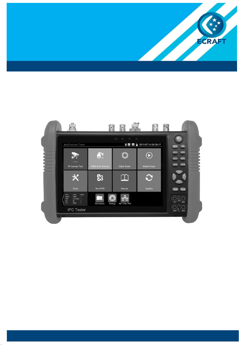
The 7 inch touch screen IP camera monitor is designed for maintenance and installation of IP cameras,
analog cameras,
8MP TVI,
8MP CVI,
8MP AHD,
8MP EX-SDI cameras,
as well as testing 4K H.264
/4K
H.265 camera via mainstream,
The 1920x1200 resolution enables it to display network HD cameras
and analog cameras in high resolution. The unit supports many ONVIF PTZ and analog PTZ control.
The combination of touch screen and key buttons make the IP camera tester very user-friendly.
The tester is also a great tool for Ethernet network testing. It can test PoE power voltage,
PING,
and IP
address searching. You can use the blue cable tracer to locate individual connected cables from a bundle
of cables. Test LAN cable for proper connection termination. Other functions include providing 25.5W
PoE power to your camera,
HDMI IN and OUT,
CVBS loop test,
testing IP and analog at the same time,
LED Flashlight,
DC 12V 3A, DC 24V 2A,
power output and much more. Its portability,
user-friendly
design and many other functions make the IP tester an essential tool for all installers or technicians.
Schmidt and Muller Telecommunications Pty Ltd trading as ELECTROCRAFT AUSTRALIA - ABN 79 067 000 426

Page.3.
2.2
Packing list
1). Tester
2). Adaptor DC12V 2A
3). Network cable tester
4).
Polymer lithium ion battery (7.6V DC 7500mAh)
5). BNC cable
6). RS485 cable
7). SC, ST connector(Only for optical power meter)
8). Multi-meter test leads one pair of red and black (only for the Multi-meter models)
9). Output Power
cable
10). Audio cable
11). TDR alligator clamp (only for TDR models)
12).
8GB SD card
13). Safety cord
14). Tool bag
15). Manual
Schmidt and Muller Telecommunications Pty Ltd trading as ELECTROCRAFT AUSTRALIA - ABN 79 067 000 426
Page.4.
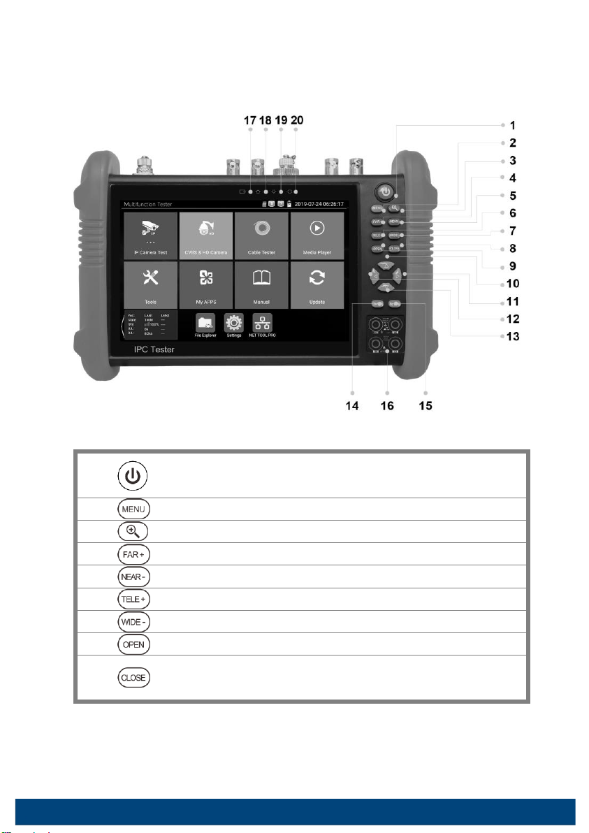
2.3
Function interface
1
Press more than 2 seconds, turn on or off the device, short press to turn on or off
the menu display
2 Menu key, press it to call short- menu.
3 4xzoom the image displays.
4 Far focus: Focus the image faraway
5 Near focus: Focus the image nearby
6 TELE: zoom in the image
7 WIDE: zoom out the image
8 Open/set, Confirm the setting of parameters, open or enlarge the aperture
9
Return/Close: Return or cancel while setting parameters of the menu, close or
decrease the aperture
Schmidt and Muller Telecommunications Pty Ltd trading as ELECTROCRAFT AUSTRALIA - ABN 79 067 000 426

Page.5.
10
Upward,
set function or add parameter. Tilt the PTZ upward
11
Rightward,
select the parameter whose value will be changed. Add the value of the
parameter. Pan the PTZ right
12
Downward,
set function or reduce the value of the parameter. Tilt the PTZ
downward
13
Leftward,
select the parameter whose value will be changed
14
Confirm key,(Long press it to capture screen interface)
15
Return/Close : Return or cancel while setting parameters of the menu,
close or
decrease the aperture
16
Multimeter interface (Optional)
17
The charge indicator: it lights red while the battery is being charged. As the
charging is complete,
the indicator turns off automatically
18
The RS485 data transmission indicator: it lights red while the data is being
transmitted
19
The data received indicator: it lights red while the data is being received
20
The power indicator: it lights green while the tester is powered on by the adapter
Schmidt and Muller Telecommunications Pty Ltd trading as ELECTROCRAFT AUSTRALIA - ABN 79 067 000 426
Page.6.
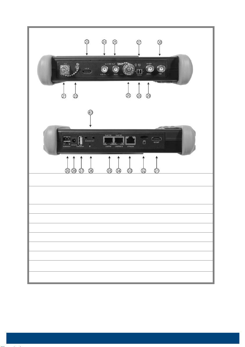
Top
interface
Bottom interface
21
Visible red laser source emits Interface (Optional)
22
DC12V3A power output,
for provisional DC power supply
23
HDMI IN (Optional )
24
CVBS IN/AHD /TVI/CVI Coaxial interface /(BNC interface)(AHD /TVI/CVI
(Optional)
)
25
Video signal output(BNC interface)/ cable tracer interface
26
Optical power meter interface (Optional)
27
LED lamp
28
RS485 Interface: RS485communication for the PTZ
29
HD-SDI/EX-SDI
input (BNC interface) ( Optional)
30
TDR cable test interface
(Optional)
Schmidt and Muller Telecommunications Pty Ltd trading as ELECTROCRAFT AUSTRALIA - ABN 79 067 000 426
Page.7.
31
HDMI output interface
32
Micro SD card moveable,(comes with 8GB,
supports up to 32GB)
33
UTP cable port: UTP cable tester port/ Cable tracer port
34
PSE power sourcing equipment. Tests PoE voltage/LAN test port
35
PoE power supply output or LAN test port (Using test PoE or non-PoE IP camera)
36
Microphone
37
USB 5V 2A power output, transmit data
38
DC 12V 2A charging interface.
39
DC 24V 2A output
40
Audio input/Audio output and earphone interface.
3. Operation
3.1 Installing the
Battery
The tester has built-in lithium ion polymer rechargeable battery. The battery cable inside battery
cabin should be disconnected for safety during transportation!
Prior to the use of the instrument,
the battery cables inside the battery cabin should be well
connected.
Usually it doesn't need to disconnect the cable at the normal use
Pressing the key continuously can power on or off the tester.
Notice:
Please
use the original adaptor and connected cable of the device!
When the battery icon
is full or the charge indicator turns off automatically,
indicate the battery
charging is completed.
Notice: When the Charge Indicator
turns off,
the battery is approximately 90%
charged.
The charging time can be extended for about 1 hour and the charging time within 12
hours will not
damage the battery.
Schmidt and Muller Telecommunications Pty Ltd trading as ELECTROCRAFT AUSTRALIA - ABN 79 067 000 426

Page.8.
Notice:
Press the key several seconds to restore the default settings when the
instrument works abnormally.
Multi-meter: the red and black multi-meter pen must insert the
corresponding
port.
Warnings:
Instrument
communication
port
is
not
permitted
access
circuit
voltage
over
6V,
otherwise
damage
the
tester.
Warnings:
Not
allow
insert
multi-meter
pen
in
the
current
terminal
to
measure
voltage.
3.2 Instrument connection
3.2.1 IP camera connection
Power an IP camera with an independent power supply, then connect the IP camera to the IPC tester's
LAN port, if the link indicator of the tester's LAN port is green and the data indicator flickers, it means
the IP camera and the IPC tester are communicating. If the two indicators don't flicker, check if the IP
camera is powered on or the network cable is not functioning properly.
Note:
1)If
the
IP
camera
requires
PoE
power,
then
connect
the
IP
camera
to
the
IP
tester's
LAN
port
.
The tester will supply PoE Power for the IP camera. Click the icon POE to turn the PoE Power off or on.
Schmidt and Muller Telecommunications Pty Ltd trading as ELECTROCRAFT AUSTRALIA - ABN 79 067 000 426

Page.9.
2) If use the tester's menu to turn off the tester's PoE power supply,
the PoE switch and the power
sourcing equipment are allowed to connect to the tester's PSE port,
and the PoE power will be supplied
to the IP camera by the tester's LAN port. On this condition,
the tester cannot receive data from IP
camera,
but the computer connected to the PoE switch can receive the data via the the tester.
Warning:
PoE
switch or PSE power sourcing equipment only can be connected to tester "PSE IN
"
port,
otherwise
will
damage
the
tester.
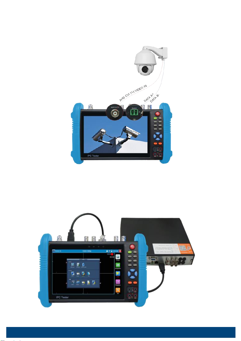
3.2.2 Analog camera connection
1)
Connect
the
camera's
video
output
to
the
IP
tester's
VIDEO
IN.
The
image
will
display
on
the
tester
after
pushing
the
PTZ
icon.
2)
CCTV
IP
Tester
"VIDEO
OUT"
interface
connect
to
the
Video
input
of
monitor
and
optical
video
transmitter
and
receiver,
the
image
display
on
the
tester
and
monitor.
3)
Connect
the
camera
or
the
speed
dome
RS485
controller
cable
to
the
tester
RS485
interface.(Note:
positive
and
negative
connection
of
the
cable)
Schmidt and Muller Telecommunications Pty Ltd trading as ELECTROCRAFT AUSTRALIA - ABN 79 067 000 426
Page.10.
3.2.3 HD Coaxial camera connection
* SDI,
CVI,
TVI,
AHD camera are classified as HD coaxial cameras. Hereby the following instruction
of how to connect SDI camera to the tester is also applied to CVI,
TVI,
and AHD camera.
1) Connect the SDI camera's video output to the IP tester's "SDI IN" interface, the image will display on
the tester. The tester only come with SDI input interface. There is no SDI output interface.
2) Connect the SDI camera or the speed dome RS485 controller cable to the tester RS485 interface.
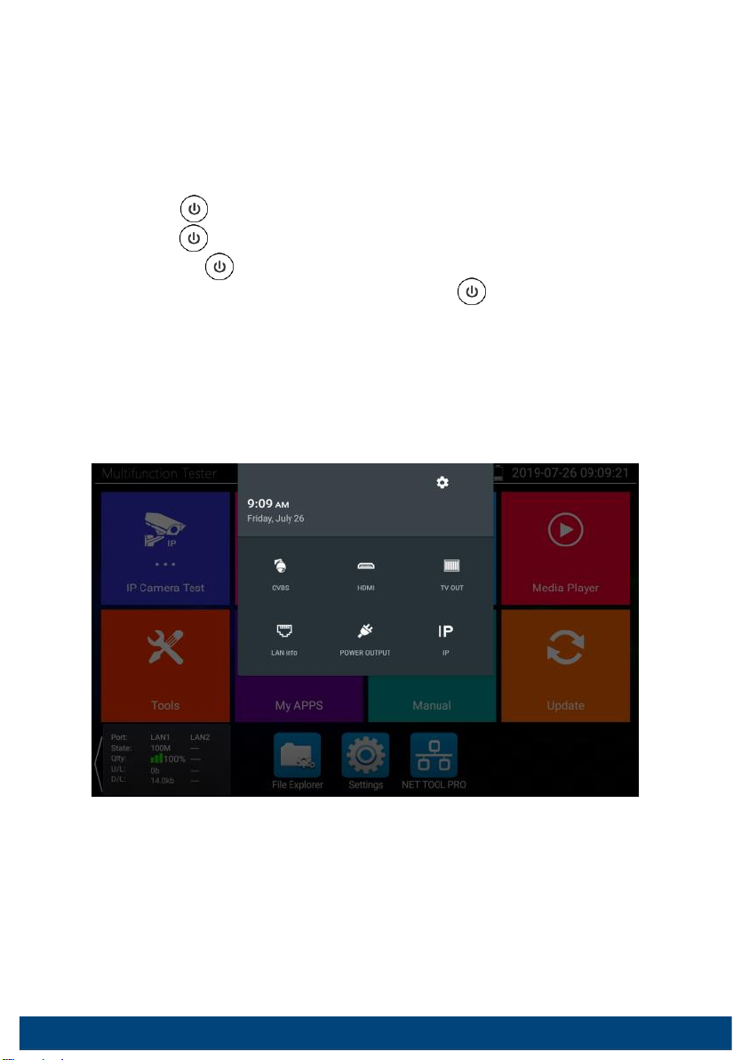
3.2.4 HDMI IN
DVR or other device's HDMI out
port connect to tester's HDMI in port,
the meter will display input image.
Schmidt and Muller Telecommunications Pty Ltd trading as ELECTROCRAFT AUSTRALIA - ABN 79 067 000 426
Page.11.
3.2.5
HDMI output
The built in HDMI output port can output live video from an analog or IP camera,
recorded files,
media
files and images to HDTV monitors. Connect an HDMI cable from the IP tester to an HDTV monitor at
any time. It supports up to 1080P resolution.
3.3 OSD menu
Press the key 2 seconds to turn on
Press the key again to turn off
short press the key to enter sleep mode,
press it again to test.
If tester works abnormally and cannot be turned off,
Press the key several seconds to turn off,
the
tester reset.
3.3.1
Drop-down
Menu
Press
and
slide
at
right
top
right
corner
twice
to
open
shortcut
menu.
The
shortcut
menu
includes
POE
power
output,
IP
settings,
Wi-Fi,
HDMI
IN,
CVBS,
Video
OUT,
LAN,
Brightness,
settings
etc.
HDMI: Click HDMI IN to enter, In HDMI
IN mode,
it can converter test from analog to digital with
dual test window IP & HDMI in
or Analog & HDMI in.
CVBS: Click icon "CVBS"to enter,
you can test IP and analog camera at the same time.
TV
OUT: Click TV
OUT to enter floating window,
connecting the BNC cable to tester and appears
analog video monitor interface,
it can test circuit and BNC cable whether normal.
LAN: Display network port or WIFI connection real-time upload and download speeds and other
Schmidt and Muller Telecommunications Pty Ltd trading as ELECTROCRAFT AUSTRALIA - ABN 79 067 000 426
Page.12.
network parameters.
Settings: Enter settings interface.
IP: Enter IP Settings interface.
POE power output: Turn on or off the tester "PoE power" app.
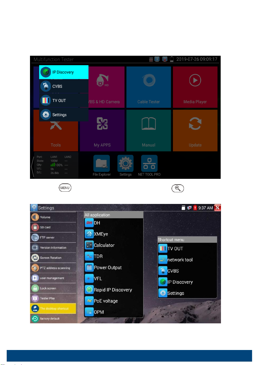
3.3.2
Short cut-menu
You can call shortcut –menu by press tester's "menu"
key,
you can self-
define shortcut -menu.
Press the key , you can turn on it, and switch functions, then press to enter app, tap other
area on the screen, to exit the menu.
You can long press any app in the all applications list, it will auto move to shortcut menu . If delete any
app in the shortcut menu, please select a app and press several seconds, it will be deleted.
Schmidt and Muller Telecommunications Pty Ltd trading as ELECTROCRAFT AUSTRALIA - ABN 79 067 000 426

Page.13.
3.3.3
Screen capture
Long press the key "enter",
can capture screen interface and save it in any time.
You can go file management to view "file Explorer
–sdcard-
Pictures—Screenshots".
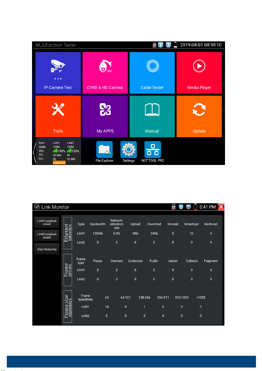
3.3.4
Link monitor
Tap icon
"Link Monitoring"
at
left corner on
the screen,
to
enter.
It can detect instrument port rate 10/100/1000M,
signal quality detection,
upload and download speed,
etc. in real time. It can be used to detect whether the network video access bandwidth of devices such as NVR
is normal.
Schmidt and Muller Telecommunications Pty Ltd trading as ELECTROCRAFT AUSTRALIA - ABN 79 067 000 426
Page.14.
When using a four-core cable to connect to a Gigabit device, would prompt "the link limited".
Advanced
link
monitor
It
is
for
monitoring
CVBS
loop,
Ethernet
statistics,
error
frame
statistics,
frame
length
etc
Schmidt and Muller Telecommunications Pty Ltd trading as ELECTROCRAFT AUSTRALIA - ABN 79 067 000 426

Page.15.
3.3.5
TesterPlay
Mobile
screen
projection
(Only
for
android
version)
The
meter
creates
WIFI
hotspot,
connect
mobile
phone
to
the
tester's
WIFI
hotspot,
or
the
tester
and
mobile
phone
connect
the
same
Wi-fi
network.
Download
and
install
Remote
control
app
to
mobile
phone, Tap icon "
",
select "TesterPlay"
app, Click "Start" will create the RTSP URL. Mobile
phone
enter
"Remote
control"
app,
please
click
"Auto
search
IP"
to
search
remote
host
IP,
then
click
"Play"
to
display
the
real-time
image
and
control
IPC
Tester.
If
can’t
find
the
IP
address,
can
click
"Manually
search
IP",
and
input
tester's
rtsp
url
to
remote
host
IP,
such
as
192.168.0.186,
then
click
"Play".
Please
contract
supplier
for
Remote
control
APP.
PC screen projection:
Install VLC player in the PC,
turn on the VLC player "Media -
Open Network Streaming",
and input the RTSP
address of on the top instrument two-dimensional code,
click "play" to view
the screen real-time projection.
Schmidt and Muller Telecommunications Pty Ltd trading as ELECTROCRAFT AUSTRALIA - ABN 79 067 000 426
Table of contents
Popular Test Equipment manuals by other brands


Timing
Timing TSC 5120A Operation and maintenance manual

Ferroli
Ferroli UT REC R+ Installation, use and maintenance manual

Extech Instruments
Extech Instruments TK32 owner's guide

Mocon
Mocon AMETEK Dansensor Lippke 5000 user guide

Powerfix Profi
Powerfix Profi PAWSB 12 A1 operating instructions

Bosch
Bosch BAT 131 Original instructions