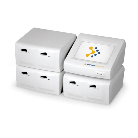
Response Biomedical RAMP READER User manual

WWW.RESPONSEBIO.COM | SPEED. PRECISION. ACCURACY.
24-HOUR TECHNICAL SUPPORT
Tel: 1-866-525-7267 (toll free) Tel: 1-604-219-
6119 (int’l)
Email:
techsupport@responsebio.com
RESPONSE CORPORATE OFFICE
Tel: 1-888-591-5577 (toll free) Tel: 1-604-456-
6010 (int’l)
Email:
customersupport@responsebio.com
C1100-1.5
OCTOBER 2019

Operator’s Manual, RAMP® Reader i
Table of Contents
1.0 INTRODUCTION ......................................................................................................................... 1
1.1 Overview .................................................................................................................................. 1
1.2 Intended Use ............................................................................................................................ 1
1.3 RAMP® System Description ..................................................................................................... 1
1.4 How the RAMP® System Works ............................................................................................... 3
1.4.1 RAMP® Reader ................................................................................................................. 3
1.4.2 RAMP® Assay/Test Kit Components ................................................................................ 3
1.4.3 Accessories ....................................................................................................................... 3
1.5 Warnings and Precautions ....................................................................................................... 4
1.5.1 Symbols and Definitions ................................................................................................... 4
1.5.2 Summary of Warnings and Precautions ........................................................................... 5
1.6 Unpacking and Installation ....................................................................................................... 6
1.6.1 Unpacking ......................................................................................................................... 6
1.6.2 RAMP® Reader Contents .................................................................................................. 6
1.6.3 Optional Accessories Contents ......................................................................................... 6
1.6.4 Installation ......................................................................................................................... 6
1.6.5 Initial Start-up .................................................................................................................... 7
1.6.6 Optional Accessories ........................................................................................................ 7
2.0 RAMP® SYSTEM OPERATION ................................................................................................ 10
2.1 Keypad Function and Use ...................................................................................................... 10
2.2 RUN/OPTIONS Menu ............................................................................................................ 12
2.3 Using Lot Cards ..................................................................................................................... 12
2.4 Running an Assay .................................................................................................................. 14
2.4.1 Entering User ID ............................................................................................................. 14
2.4.2 Entering User P.I.N. – “User Lock-out” Mode (P.I.N. Enabled) ...................................... 15
2.4.3 Entering Sample ID ......................................................................................................... 15
2.4.4 Inserting a Cartridge ....................................................................................................... 16
2.5 Using the OPTIONS Menu ..................................................................................................... 19
2.5.1 Output Results ................................................................................................................ 19
2.5.2 View Results ................................................................................................................... 22
2.5.3 Run Internal Quality Control (IQC) .................................................................................. 24
2.5.4 Run Liquid Quality Control (LQC) ................................................................................... 25
2.5.5 System Settings .............................................................................................................. 25
2.5.6 Exiting OPTIONS Menu .................................................................................................. 25
2.6 Using the SYSTEM SETTINGS Menu ................................................................................... 26
2.6.1 Accessing the SYSTEM SETTINGS Menu..................................................................... 26
2.6.2 Set Master P.I.N. ............................................................................................................. 27
2.6.3 Setting the System Clock ................................................................................................ 27
2.6.4 Enable User ID/P.I.N....................................................................................................... 28
2.6.5 Edit User ID/P.I.N. ........................................................................................................... 28
2.6.6 Print Settings ................................................................................................................... 29
2.6.7 Transfer Users ................................................................................................................ 31
2.6.8 Erase Memory ................................................................................................................. 32
2.6.9 Set IQC Timer ................................................................................................................. 33
2.6.10 Set LQC Timer ................................................................................................................ 33
2.6.11 Reset LQC Timer ............................................................................................................ 34
2.6.12 Test Counters ................................................................................................................. 35
2.6.13 Connectivity .................................................................................................................... 35
2.6.14 Enable Sound ................................................................................................................. 35
2.6.15 Exit Menu ........................................................................................................................ 36

Operator’s Manual, RAMP® Reader ii
3.0 MAINTENANCE ........................................................................................................................ 37
3.1 Overview ................................................................................................................................ 37
3.2 Cleaning and Decontamination .............................................................................................. 37
3.3 Battery Care ........................................................................................................................... 37
4.0 TROUBLESHOOTING GUIDE .................................................................................................. 38
4.1 Power-On Self-Test Messages / IQC Messages ................................................................... 38
4.2 Lot Card / Barcode Messages................................................................................................ 40
4.3 Transport Messages .............................................................................................................. 41
4.4 Test Run Messages ............................................................................................................... 42
4.5 General Messages ................................................................................................................. 44
5.0 READER SPECIFICATIONS .................................................................................................... 45
APPENDIX A ........................................................................................................................................ 47
Connecting the RAMP® Reader to Accessories ............................................................................... 47
Printer / Computer Connections ........................................................................................................ 47
Reader-to-Reader Connections ........................................................................................................ 47
Barcode Wand Connections ............................................................................................................. 47
APPENDIX B ........................................................................................................................................ 48
User Agreement and Warranty ......................................................................................................... 48
Return Policy ..................................................................................................................................... 48
Receipt of Delivery ............................................................................................................................ 48
Exchange Policy................................................................................................................................ 48
Warranty ............................................................................................................................................ 49
Exclusions ......................................................................................................................................... 49
Liability Limitations ............................................................................................................................ 49
Recall Policy ...................................................................................................................................... 49
End User License Agreement ........................................................................................................... 50
Software Updates.............................................................................................................................. 50
Feedback .......................................................................................................................................... 50
Governing Law .................................................................................................................................. 50
APPENDIX C ........................................................................................................................................ 51
Contact Information ........................................................................................................................... 51
Response Biomedical Customer Service ......................................................................................... 51
European Authorized Representative ............................................................................................... 51

Operator’s Manual, RAMP® Reader 1
1.0 INTRODUCTION
1.1 Overview
The RAMP® System is a rapid, quantitative immunochromatographic system for performing in vitro
diagnostic analyses on a variety of analytes. The System can be used for various applications, from
use in a clinical setting (point-of-care, central or STAT laboratory) to use for onsite screening of
environmental samples.
The System is comprised of the RAMP® Reader (“Reader”) and various RAMP® Assay/Test kits
(“Kits”). Optional accessories include a barcode wand, printer, and cabling required to connect the
Reader to a computer, printer or another Reader. Calibration and expiration information for Kits are
input to the Reader through Lot Cards enclosed with the Kits. The Reader only accepts Kits that are
designed specifically for use with this instrument.
To perform a test, the operator prepares the appropriate sample according to the Test Kit Instructions
for Use, places an aliquot of the sample into the sample well of the Test Cartridge and inserts the
Test Cartridge into the Reader.
Once the Cartridge has been inserted, no further intervention is required. A barcode on the bottom of
the Cartridge is read to determine the Kit lot number. Information loaded with the Lot Card identifies
lot-specific parameters and expiration date. This ensures that an expired Cartridge is not used.
Analysis time is analyte-specific and averages 15 minutes across Assays (Test-dependent). Results
may be viewed on the Reader LCD screen and/or output to a printer or computer. Operator input is
accepted from the Reader’s keypad or an optional barcode wand.
The RAMP® System should only be used by trained personnel.
1.2 Intended Use
The RAMP® Reader is a general use fluorometer that analyzes results produced by immunoassays
manufactured by Response Biomedical Corp.
1.3 RAMP® System Description
Each disposable, single-use Test Cartridge houses an analyte-specific, immunochromatographic strip
on which the Assay runs. The RAMP® System uses an internal calibrator incorporated into each test
strip to compensate for test-to-test variations.
To perform an assay, the operator transfers a sample into the sample well of a Cartridge and inserts
the Cartridge into the Reader. The sample is drawn by capillary action along the membrane. Analyte
present in the sample interacts and binds with the fluorescently-labeled antibodies forming an
antibody-antigen complex. The complexes and labeled antibodies are subsequently captured at the
detection and control zones. When the reaction in the Cartridge is complete, the Reader scans the
assay strip and detects fluorescence in the detection and the internal standard zones, then by
comparing fluorescence captured at the detection and internal standard zones, converts this ratio
(RAMP® Ratio) into an analyte concentration using lot-specific calibration data. Refer to Test Kit

Introduction
Operator’s Manual, RAMP® Reader 2
Instructions for Uses for more details. The use of the RAMP® Ratio significantly reduces variation
due to sample, operator and membrane differences.
The assay result is displayed on the Reader’s LCD (liquid crystal display) following test development.
The result is stored and can be printed, uploaded to a PC, or deleted.
Lot specific information for each Kit lot is entered using a pre-programmed Lot Card, included with
each Kit. Prior to running assays from a new Kit, the Lot Card is inserted into a slot on the front of the
Reader just below the keypad. The Reader automatically uploads information, including the lot
number, expiration (Use-by) date, and lot-specific parameters for that Kit.
The Reader scans the barcode graphic on the bottom of the Cartridge. This allows the Reader to use
the barcode information to select the lot-specific data stored in the non-volatile memory of the
instrument.
Built-in Internal Quality Control (IQC) performs an automated test of all Reader analytical systems at
start-up and on a scheduled or operator-determined basis to provide a record of proper Reader
functionality.

Introduction
Operator’s Manual, RAMP® Reader 3
1.4 How the RAMP® System Works
1.4.1 RAMP® Reader
The Reader is a scanning fluorometer and data analysis system used for the measurement of
fluorescence in various RAMP® immunoassay applications (Figure 1-1). The Reader can be
operated on battery power or powered via an AC adapter
1.4.2 RAMP® Assay/Test Kit Components
The Kits are used in conjunction with the Reader to detect the concentration of analyte in an aqueous
sample. There are several components associated with the Kits, including a Lot Card and applicable
sample handling supplies. For more information on the Kit, components, operation and sample
handling for the assay, refer to the Test Kit Instructions for Use.
NOTE: The Reader is only designed to be used with Kits manufactured by Response
Biomedical Corporation.
1.4.3 Accessories
There are a number of optional accessories that can be purchased for use with the RAMP® System.
All items are available from Response Biomedical. Please contact your local distributor or Response
Biomedical Customer Service (Appendix C) if you require any of the following accessories
1.4.3.1 Printer
A printer can be connected to the Reader via the RS-232 serial port on the back panel, and is used to
create a hard copy of the assay results. The recommended printer is the Citizen iDP 3110.
1.4.3.2 Barcode Wand
A barcode wand can be connected to the Reader via the back panel and used to enter sample
identification or operator identification into the Reader instead of using the Reader keypad. The
barcode wand is capable of reading UPC, Codabar, EAN, ISBN or similar barcode information.
1.4.3.3 Computer Connections
Detailed instructions for enabling assay results to be output to a computer can be obtained from
Response Biomedical Technical Support.
1.4.3.4 Reader to Reader Cable
By linking Readers together with the appropriate cables, User ID (user identification) and P.I.N.
(personal identification number) information can be transferred to another Reader. Appendix A
provides more details.

Operator’s Manual, RAMP®
Reader
1.5
Warnings and Precautions
1.5.1
Symbols and Definitions
Read all contents of this manual prior to use.
The following symbols are used on the RAMP
the text of this user manual:
WARNING!
Indicates a hazardous situation, which if not avoided, could result in death
or injury, e.g., fire, electrical shock or explosion.
WARNING!
Indicates an electrical shock hazard
CAUTION
Indicates a situation, which if not avoided, could result in damage to the
device.
Manufacturer
In Vitro
diagnostic medical device
Authorized representative in the European Community
Consult operat
On
(power supply)
Off
(power supply)
Reader
Warnings and Precautions
Symbols and Definitions
Read all contents of this manual prior to use.
The following symbols are used on the RAMP
® Reader, related components a
nd accessories, or in
WARNING!
Indicates a hazardous situation, which if not avoided, could result in death
or injury, e.g., fire, electrical shock or explosion.
WARNING!
Indicates an electrical shock hazard
CAUTION
!
Indicates a situation, which if not avoided, could result in damage to the
Manufacturer
diagnostic medical device
Authorized representative in the European Community
Consult operat
ing instructions
(power supply)
(power supply)
Introduction
4
nd accessories, or in
Indicates a hazardous situation, which if not avoided, could result in death
Indicates a situation, which if not avoided, could result in damage to the

Operator’s Manual, RAMP®
Reader
1.5.2
Summary of Warnings and Precautions
Observe the following precautions when operating the RAMP
1.5.2.1 WARNING!
Reduce the risk associated with hazardous voltage.
Unplug and power off the Reader before cleaning.
Do not immerse the Reader in water.
1.5.2.2 WARNING! R
educe the risk associated with potenti
Do not spill sample on the Reader
biohazard.
If a spill occurs, disinfect external surfaces only using a soft cloth containing a
solution of 0.5% bleach, 70% isopropyl alcohol or 70% ethanol.
Use appropriate precautions in the collection, handling and disposal of specimens,
including diluted specimens and
(Refer to analyte specific package insert for instructions).
Dispose of instrum
ent and accessories in accordance with federal, state, and local
requirements
for potential biohazards.
1.5.2.3
WARNING! Reduce the risk associated with inaccurate results.
Keep movement of the Reader to a minimum while an assay is in process, however sitting
t
he Reader in an idling or moving vehicle should not inh
1.5.2.4 CAUTION! R
educe the risk of
Do not spill sample
near
contact with electrical components inside the Reader may damage the Reader.
enters the Cartridge
port, power off the device immediately to prevent damage and no not
power on until any spill is dry.
Do not touch the gold contact pads
Store Lot Cards in the anti
Use only Response Biomedical
DO NOT connect the barcode wand to Reader
may result
in damage to the barcode wand
.
Reader
Summary of Warnings and Precautions
Observe the following precautions when operating the RAMP
® System.
Reduce the risk associated with hazardous voltage.
Unplug and power off the Reader before cleaning.
Do not immerse the Reader in water.
educe the risk associated with potenti
ally infectious patient samples.
Do not spill sample on the Reader
or the outside of a Cartridge
as they become a po
If a spill occurs, disinfect external surfaces only using a soft cloth containing a
solution of 0.5% bleach, 70% isopropyl alcohol or 70% ethanol.
Use appropriate precautions in the collection, handling and disposal of specimens,
including diluted specimens and
Test Kit contents
as these items are potential biohazards
(Refer to analyte specific package insert for instructions).
ent and accessories in accordance with federal, state, and local
for potential biohazards.
WARNING! Reduce the risk associated with inaccurate results.
Keep movement of the Reader to a minimum while an assay is in process, however sitting
he Reader in an idling or moving vehicle should not inh
ibit the development of a test.
educe the risk of
instrument or accessory damage.
near
the Reader Cartridge port
or on the outside of a
contact with electrical components inside the Reader may damage the Reader.
port, power off the device immediately to prevent damage and no not
power on until any spill is dry.
Do not touch the gold contact pads
on the Lot Cards.
Store Lot Cards in the anti
-static pouches provided.
Use only Response Biomedical
-
supplied or recommended accessories with the Reader.
DO NOT connect the barcode wand to Reader
while
the Reader is turned ON.
in damage to the barcode wand
.
Introduction
5
ally infectious patient samples.
as they become a po
tential
If a spill occurs, disinfect external surfaces only using a soft cloth containing a
Use appropriate precautions in the collection, handling and disposal of specimens,
as these items are potential biohazards
.
ent and accessories in accordance with federal, state, and local
Keep movement of the Reader to a minimum while an assay is in process, however sitting
ibit the development of a test.
or on the outside of a
Cartridge. Liquid
contact with electrical components inside the Reader may damage the Reader.
If a spill
port, power off the device immediately to prevent damage and no not
supplied or recommended accessories with the Reader.
the Reader is turned ON.
Doing so

Introduction
Operator’s Manual, RAMP® Reader 6
1.6 Unpacking and Installation
1.6.1 Unpacking
The Reader and/or optional accessories are packed in a cushioned container for maximum protection
during shipment. If the shipping container is damaged, inspect the Reader as it is unpacked. If the
Reader is damaged, notify the carrier and your distributor, or Response Biomedical Corporation to
arrange for immediate repair or replacement. Retain the shipping container and all packaging
material for repackaging.
To unpack the Reader, remove the packaging and carefully lift out the Reader. Place the Reader on
a dry, clean, level surface. Remove the AC Adapter and Power Cord and check the label to confirm
country-specific voltage requirements. Remove remaining contents and compare with the packing
slip or list below. If any of the contents are missing, contact your distributor or Response Biomedical
Corporation Customer Service (Appendix C).
1.6.2 RAMP® Reader Contents
Quantity Instrument
1 RAMP® Reader
1 Reader AC Adapter with adaptable plug
(region-specific)
1 Reader Operator’s Manual
1.6.3 Optional Accessories Contents
Quantity Optional Accessories
1 Printer (with associated accessories)
1 Barcode Wand
1 Computer Connection Cable
1 Reader-to-Reader Cable
1.6.4 Installation
The Reader should be plugged in prior to use in order to charge the battery. Connect the AC Adapter
to the Input Port on the back panel of the Reader (Figure 1-2) and plug into an AC outlet. It requires
24 hours to fully charge the battery but it can be used for testing while it is charging.
NOTE: Do not connect or disconnect the Reader from an AC outlet while a test is in
progress.
WARNING! Only use the charger provided with your RAMP® Reader.

Operator’s Manual, RAMP®
Reader
1.6.5 Initial Start-up
The power button is located on the back panel of the Reader (Figure
on, the Reader performs a Power
certain pre-
set parameters. The POST includes calibration verification, optical system verification,
real-
time clock test, transport movement test, and a bat
battery at the time of the POST). If the measured battery voltage is low, a warning message appears
on the LCD along with an audible alarm. If this occurs, the Reader should be plugged into an AC
outlet using t
he supplied Adapter.
NOTE: A fully-
charged battery will allow approximately 100 tests to be run before re
charging is required. In the event that a Reader is
low. It takes approximately 24 hours to fully rechar
may be operated with the AC Adapter during battery recharging. Refer to Section
recommended battery care.
NOTE: Ensure
that the battery is sufficiently charged or that the Reader is connected to an
AC outlet prior to performing a test.
outlet once the test has started
The Reader can also function in an enhanced control
function. This requires the setting of a Master P.I.N., which provides controlled access to the
SYSTEM SETTINGS Menu.
Functions available through the SYSTEM SETTINGS Menu include
changing the instrument clock, s
operator data, erasing data, selecting print settings, test counters, erasing memory, and setting QC
timers. The User Lock-
out mode ensures that only operators with a valid controlled P.I.N
to run tests on the Reader.
To operate the Reader with User Lock
by setting a Master P.I.N. (Section
(Section 2.6.4).
NOTE: Ensure that
operators have read and understood the Operator’s Manu
Test Kit Instructions for Use
1.6.6
Optional Accessories
If using a printer, connect it to the Reader via the RS
See Appendix A
for printer compatibility information.
If the Reader is connected to a computer or another Reader, ensure that the serial connect
properly secured. See
Appendix A
CAUTION!
If using the optional Barcode Wand accessory, ensure that it is properly
connected to the Reader via the Barcode Wand connector port on the
turning the Reader on. Failure to do so may result in damage to the Barcode Wand.
Reader
The power button is located on the back panel of the Reader (Figure
1-2
). When the power is turn
on, the Reader performs a Power
-On Self-
Test (“POST”) to ensure the system is operating within
set parameters. The POST includes calibration verification, optical system verification,
time clock test, transport movement test, and a bat
tery test (if the Reader is operating on the
battery at the time of the POST). If the measured battery voltage is low, a warning message appears
on the LCD along with an audible alarm. If this occurs, the Reader should be plugged into an AC
he supplied Adapter.
charged battery will allow approximately 100 tests to be run before re
charging is required. In the event that a Reader is
left
on for 24 hours, the battery may run
low. It takes approximately 24 hours to fully rechar
ge the battery, however, the Reader
may be operated with the AC Adapter during battery recharging. Refer to Section
recommended battery care.
that the battery is sufficiently charged or that the Reader is connected to an
AC outlet prior to performing a test.
Do not connect or disconnect the Reader from an AC
outlet once the test has started
.
The Reader can also function in an enhanced control
led
manner by enabling the “User Lock
function. This requires the setting of a Master P.I.N., which provides controlled access to the
Functions available through the SYSTEM SETTINGS Menu include
changing the instrument clock, s
etting and enabling User IDs and associated P.I.N.s, transferring
operator data, erasing data, selecting print settings, test counters, erasing memory, and setting QC
out mode ensures that only operators with a valid controlled P.I.N
To operate the Reader with User Lock
-
out, ensure the SYSTEM SETTINGS Menu has limited access
by setting a Master P.I.N. (Section
2.6.2
) and that a User ID and P.I.N. are defined for each operator
operators have read and understood the Operator’s Manu
Test Kit Instructions for Use
before attempting to perform a test.
Optional Accessories
If using a printer, connect it to the Reader via the RS
-
232 serial port on the back panel (Figure
for printer compatibility information.
If the Reader is connected to a computer or another Reader, ensure that the serial connect
Appendix A
for serial port compatibility information.
If using the optional Barcode Wand accessory, ensure that it is properly
connected to the Reader via the Barcode Wand connector port on the
back panel PRIOR to
turning the Reader on. Failure to do so may result in damage to the Barcode Wand.
Introduction
7
). When the power is turn
ed
Test (“POST”) to ensure the system is operating within
set parameters. The POST includes calibration verification, optical system verification,
tery test (if the Reader is operating on the
battery at the time of the POST). If the measured battery voltage is low, a warning message appears
on the LCD along with an audible alarm. If this occurs, the Reader should be plugged into an AC
charged battery will allow approximately 100 tests to be run before re
-
on for 24 hours, the battery may run
ge the battery, however, the Reader
may be operated with the AC Adapter during battery recharging. Refer to Section
3.3 for
that the battery is sufficiently charged or that the Reader is connected to an
Do not connect or disconnect the Reader from an AC
manner by enabling the “User Lock
-out”
function. This requires the setting of a Master P.I.N., which provides controlled access to the
Functions available through the SYSTEM SETTINGS Menu include
etting and enabling User IDs and associated P.I.N.s, transferring
operator data, erasing data, selecting print settings, test counters, erasing memory, and setting QC
out mode ensures that only operators with a valid controlled P.I.N
. are allowed
out, ensure the SYSTEM SETTINGS Menu has limited access
) and that a User ID and P.I.N. are defined for each operator
operators have read and understood the Operator’s Manu
al and the
232 serial port on the back panel (Figure
1-2).
If the Reader is connected to a computer or another Reader, ensure that the serial connect
ion is
If using the optional Barcode Wand accessory, ensure that it is properly
back panel PRIOR to
turning the Reader on. Failure to do so may result in damage to the Barcode Wand.

Operator’s Manual, RAMP®
Reader
Reader
Figure 1-1: RAMP® Reader
Introduction
8

Operator’s Manual, RAMP®
Reader
Figure
Reader
Figure
1-2: RAMP® Reader Rear Panel View
Introduction
9

RAMP® System Operation
Operator’s Manual, RAMP® Reader 10
2.0 RAMP® SYSTEM OPERATION
2.1 Keypad Function and Use
To interface with the RAMP® System, use the keypad (Figure 2-1) when prompted by the Reader
display.
The keypad consists of ten alphanumeric character keys and two function keys, [Options] and [Enter].
To input a specific letter or number, press the key to scroll through the choices until the desired
character is displayed. For example, to input the letter R, press the key marked [PQR 6] four times,
until the letter R is displayed. When the character of choice has been selected, press a different key
(other than the key initially pressed) to enter the character. The blank cursor will then move one
character position to the right and display the new character. Press [Enter] to accept the displayed
character string and proceed to the next step. Alternatively, a two-second pause after the desired
character is selected will automatically enter the character and move the blank cursor one space to
the right. This provides a means of entering multiple characters on the same key.
NOTE: When keying in a P.I.N., only the numerical character for each key (0-9) can be
selected.
Press [Options] to erase and move the cursor one step to the left. This provides a backspace or
correction function. Press [Options] again to erase the displayed character and move the cursor one
more step to the left. Pressing a new character key will overwrite the displayed character above the
cursor. If either [Options] or [Enter] key is pressed when no characters are shown on the display, this
step is aborted and the operator is returned to the RUN/OPTIONS Menu.
The character keys [ABC 1] and [GHI 3] also function as the up [▲] and down [▼] keys respectively,
allowing the operator to scroll through the OPTIONS menu or move the displayed “>” cursor to select
specific options. Holding down the [▲] or [▼] key causes the display to scroll through the available
choices. The “>” cursor points to the currently selected option. Whenever the OPTIONS Menu and
associated functions are used, the keypad is limited to using the [▲], [▼], [Options], and [Enter] keys.
All other character keys are inactive except when required for Editing User ID, User P.I.N., Master
P.I.N. and adding printout information.

Operator’s Manual, RAMP®
Reader
RAMP
® System Operation
Reader
Figure 2-1: RAMP® Reader Keypad
® System Operation
11

RAMP® System Operation
Operator’s Manual, RAMP® Reader 12
2.2 RUN/OPTIONS Menu
When the Reader is turned on, it initially performs a Power-On Self-Test and displays the following
animation on the display for one second while emitting two short beeps:
The following message scrolls across the screen from right to left and remains displayed for a few
seconds (X.XX corresponds to the software version):
NOTE: If errors are found during the Power-On Self-Test, see Section 4.1 for detail.
When the Reader is ready for operation, the RUN/OPTIONS Menu is displayed:
At this point, the following actions may be performed:
Insert a Lot Card to upload lot information (Section 2.3).
Run an Assay (Section 2.4).
Access the OPTIONS menu (Section 2.5).
NOTE: If a critical system failure is found during the Power-On Self-Test or during IQC, the
Reader will lock out the operator from running samples or Liquid Quality Control (LQC).
Pressing [Enter] at either the RUN/OPTIONS or RUN LQC/EXIT prompts will display this
message:
Press any key to return to the menu. The OPTIONS Menu is still accessible to output, print or view
results.
2.3 Using Lot Cards
Each Kit includes a Lot Card that is individually packaged in an anti-static pouch. The Lot Card
provides information, including lot-specific data and the expiration (Use-by) date of each Kit. Use the
Lot Card to input the specific lot information into the Reader before using the Cartridges. This step is
only required once prior to the use of a new lot.
SERVICE REQUIRED
PRESS KEY TO PROCEED
RUN TEST: <Enter>
OPTIONS: <Options>
*** RAMP READER ***
*** Version X.XX ***
■■■■■■■■■■■■■■■■■■■■
■■■■■■■■■■■■■■■■■■■■

Operator’s Manual, RAMP®
Reader
To load the lot information, hold the Lot Card by the label with the arrow / text facing up, then insert
the L
ot Card with the arrow pointing toward the Reader, contact end first
the keypad on the front of the Reader (Figure
CAUTION!
Do not touch the
The Lot Card must
be inserted before the accompanying new
not inserted prior to running the first
appropriate Lot Card (Section
4.2
Refer to the following steps for loading Lot Card information
At the RUN/OPTIONS Menu prompt
emitted and the screen displays the following message:
When the Lot Card is accepted, indicating that the Lot information has been successfully uploaded,
the following message is displayed:
After the Lot Card data has been stored in memory, the Reader beeps twice and prompts the
operator with the following instruction:
When the Lot Card is removed
, the Reader will beep once.
CAUTION!
The Lot Card should be kept in the anti
and retained for the life of the
NOTE:
Lot Card information will only upload successfully if it is inserted when either the
RUN/OPTIONS or RUN LQC/EXIT Menus are displayed. The Reader will not acknowledge
Lot Card insertion at any other time. It is only necessary to insert the Lot Card once p
l
ot as the lot information is retained even when the Reader power is switched off. The
Reader can store data for up to 50 separate lot numbers. When the memory is full, the
oldest data is overwritten when a new Lot Card is inserted. If a Lot Card
can
not be read, the following message is displayed:
4.2)
The Reader verifies the expiry (Use
expiry date, the Reader emits an audible alarm and displays the error message:
EXPIRED! (Section 4.2) Dat
a from an expired lot is not copied into the Reader’s memory.
RAMP
® System Operation
Reader
To load the lot information, hold the Lot Card by the label with the arrow / text facing up, then insert
ot Card with the arrow pointing toward the Reader, contact end first
,
into the slot located under
the keypad on the front of the Reader (Figure
1-1).
Do not touch the
gold contact pads on the Lot Card.
be inserted before the accompanying new
Kit lot
can be used. If the Lot Card is
not inserted prior to running the first
Cartridge
for a new lot, the operator will be prompted to inser
4.2
).
Refer to the following steps for loading Lot Card information
.
At the RUN/OPTIONS Menu prompt
, insert the Lot Card. Afte
r the Lot Card is inserted, a beep is
emitted and the screen displays the following message:
When the Lot Card is accepted, indicating that the Lot information has been successfully uploaded,
the following message is displayed:
After the Lot Card data has been stored in memory, the Reader beeps twice and prompts the
operator with the following instruction:
, the Reader will beep once.
The Lot Card should be kept in the anti
-
static pouch provided for safe storage
and retained for the life of the
Kit.
Lot Card information will only upload successfully if it is inserted when either the
RUN/OPTIONS or RUN LQC/EXIT Menus are displayed. The Reader will not acknowledge
Lot Card insertion at any other time. It is only necessary to insert the Lot Card once p
ot as the lot information is retained even when the Reader power is switched off. The
Reader can store data for up to 50 separate lot numbers. When the memory is full, the
oldest data is overwritten when a new Lot Card is inserted. If a Lot Card
not be read, the following message is displayed:
LOT CARD READ-
ERROR!
The Reader verifies the expiry (Use
-by) date against its i
nternal clock. If the current date exceeds the
expiry date, the Reader emits an audible alarm and displays the error message:
LOT CARD
a from an expired lot is not copied into the Reader’s memory.
REMOVE LOT CARD
LOT DATA VERIFIED
SAVING DATA...
READING LOT CARD
PLEASE WAIT...
® System Operation
13
To load the lot information, hold the Lot Card by the label with the arrow / text facing up, then insert
into the slot located under
can be used. If the Lot Card is
for a new lot, the operator will be prompted to inser
t the
r the Lot Card is inserted, a beep is
When the Lot Card is accepted, indicating that the Lot information has been successfully uploaded,
After the Lot Card data has been stored in memory, the Reader beeps twice and prompts the
static pouch provided for safe storage
Lot Card information will only upload successfully if it is inserted when either the
RUN/OPTIONS or RUN LQC/EXIT Menus are displayed. The Reader will not acknowledge
Lot Card insertion at any other time. It is only necessary to insert the Lot Card once p
er Kit
ot as the lot information is retained even when the Reader power is switched off. The
Reader can store data for up to 50 separate lot numbers. When the memory is full, the
is defective or
ERROR!
(Section
nternal clock. If the current date exceeds the
LOT CARD
a from an expired lot is not copied into the Reader’s memory.

RAMP® System Operation
Operator’s Manual, RAMP® Reader 14
2.4 Running an Assay
2.4.1 Entering User ID
If the User ID option is enabled, the following screen is displayed after pressing [Enter] at the
RUN/OPTIONS prompt:
If the User ID option is disabled, this screen does not appear and the test proceeds to Sample ID
entry after pressing [Enter] (Section 2.4.2).
NOTE: The default for the User ID option is ENABLED. For information on how to enable /
disable the User ID via the SYSTEM SETTINGS Menu, see Section 2.6.4.
When the “>” cursor is pointing to the SELECT USER ID prompt, press [Enter]. The following prompt
is displayed:
Use the [▲] or [▼] keys to display the appropriate User ID and press [Enter] to select. The Reader
then progresses to the ENTER SAMPLE ID: (Section 2.4.3). The Reader provides up to 250 USER
ID’s of up to 20 characters each. The default entries for User ID’s are USER001, USER002, through
to USER250. To edit the User ID’s, see Section 2.6.5.
To return to the SELECT USER ID/ENTER USER ID screen without selecting a displayed User ID,
press [Options].
To enter a User ID from the keypad, press [▼] to move the “>” cursor to ENTER USER ID and press
[Enter]. The following screen is displayed:
Use the keypad to enter up to 20 alphanumeric characters. The screen limits the number of
characters to a maximum of 20.
Alternatively, use the optional Barcode Wand to enter the User ID. If the Barcode Wand is attached,
a loud beep will sound when the ENTER USER ID prompt is displayed.
Press [Enter] to accept the information entered by the keypad or Barcode Wand. This will link the
User ID to the Sample ID entered in the next step.
If there no characters entered, pressing [Options] returns the screen to the SELECT USER ID menu.
ENTER USER ID:
_
SELECT USER ID:
USER001
> SELECT USER ID
ENTER USER ID

RAMP® System Operation
Operator’s Manual, RAMP® Reader 15
2.4.2 Entering User P.I.N. – “User Lock-out” Mode (P.I.N. Enabled)
If the User ID and P.I.N. options are enabled, the following screen is displayed after pressing [Enter]
to select the appropriate User ID:
If the User P.I.N. option is disabled, this screen does not appear and the Reader progresses to
ENTER SAMPLE ID screen (Section 2.4.3).
NOTE: The default for the User P.I.N. option is DISABLED. For information on how to
“enable / disable” the User P.I.N. via the SYSTEM SETTINGS Menu, see Section 2.6.4.
Use the keypad to enter the numeric User P.I.N. required and press [Enter]. The following screen is
displayed briefly:
If the User P.I.N. is recognized, the Reader progresses to the ENTER SAMPLE ID screen (Section
2.4.3).
If the User P.I.N. is not recognized, the following screen is displayed:
Press any key to restore the screen to the RUN/OPTIONS prompt. Press [Enter] to retry, or consult
supervisor.
2.4.3 Entering Sample ID
After the USER ID and/or P.I.N. is entered (if enabled), a beep is emitted and the following prompt is
displayed:
NOTE: If the USER ID is disabled, the above prompt will be displayed after pressing
[Enter] from the initial RUN/OPTIONS screen.
ENTER SAMPLE ID:
_
P.I.N. IS INCORRECT!
PRESS KEY TO PROCEED
VERIFYING P.I.N.
PLEASE WAIT...
ENTER USER P.I.N.:
_ ***************

RAMP® System Operation
Operator’s Manual, RAMP® Reader 16
A Sample ID of up to 20 alphanumeric characters can be input using the letter, number and space
keys (Section 2.1).
When all characters have been entered, press [Enter] to store the displayed Sample ID into memory.
If a letter or number has been inadvertently entered, press [Options] to clear the entry.
Alternatively, the optional Barcode Wand may be used to enter the Sample ID. If the Barcode Wand
is attached, a loud beep will sound when the ENTER SAMPLE ID prompt is displayed.
Swipe the Barcode Wand across the barcoded information in either direction. A beep will sound if the
swipe is successful. Accept the displayed information by pressing [Enter]. To erase the entry, press
[Options].
NOTE: If the Reader is operating on the internal battery and a Sample ID is not entered
within 30 seconds, the screen returns to the RUN/OPTIONS Menu. Pressing [Options] or
[Enter] after clearing all letters or numbers also returns the screen to the RUN/OPTIONS
Menu.
Once the Sample ID has been accepted and entered, the system proceeds to the ADD SAMPLE,
THEN INSERT CARTRIDGE prompt (Section 2.4.4).
2.4.4 Inserting a Cartridge
After accepting a Sample ID, the Reader activates an internal barcode detector and prompts the
operator to:
NOTE: The Reader will remain on this screen for 5 minutes or until a Cartridge is inserted.
If the sample is not available at this time or if the test is to be aborted, press [Options] to
return to the RUN/OPTIONS Menu.
Prepare a Cartridge with sample following the procedure described in the appropriate Assay Package
Insert.
Insert the Cartridge into the Cartridge Insertion Port (Figure 2-2A) by gently pushing the Cartridge
until firm resistance is felt (Figure 2-2B). Do not attempt to force the Cartridge all the way into the
slot. The Reader will automatically guide the Cartridge while reading the barcode graphic on the
bottom. The barcode contains the assay lot number and graphic markings to indicate to the Reader
that the Cartridge has been correctly inserted.
ADD SAMPLE, THEN
INSERT CARTRIDGE
ENTER SAMPLE ID:
R_

Operator’s Manual, RAMP®
Reader
Figure
2-2A
CAUTION!
To prevent damage to internal components of the Reader, it is important to
prevent excess sample from getting onto the
Clean any spills before inserting the
NOTE:
For most assays,
Reader following sample addition. If the
seconds of sample addition, the
displayed. This will
abort
If the Reader is unable to detect the
CARTRIDGE, THEN RE-
INSERT is displayed (Section
When the inserted Cartridge
is detected, the Reader automatical
displays the following:
Once the Cartridge
barcode is successfully read, the Reader searches its memory for the
corresponding lot-
specific data. If the matching data cannot be found, the operator is prompted to
INSERT LOT CARD FOR LOT #Mxxxxx (Section
If the Reader’s memor
y contains the corresponding lot information for the
prompts indicating the progress of the analysis are displayed, as shown in the following example of a
Troponin test:
Running time is displayed as a count
RAMP
® System Operation
Reader
Figure
2-2: Inserting a Test Cartridge
2-2B
To prevent damage to internal components of the Reader, it is important to
prevent excess sample from getting onto the
Cartridge
or spilling out of the sample well.
Clean any spills before inserting the
Cartridge into the Reader.
For most assays,
it is important to IMMEDIATELY insert the
Cartridge
Reader following sample addition. If the
Cartridge
is not inserted into the Reader within 30
seconds of sample addition, the
Cartridge may be rejected and
an error message
abort
the test and require another test to be performed (Section
If the Reader is unable to detect the
Cartridge
a beep is emitted and the error message REMOVE
INSERT is displayed (Section
4.4).
is detected, the Reader automatical
ly pulls the
Cartridge
barcode is successfully read, the Reader searches its memory for the
specific data. If the matching data cannot be found, the operator is prompted to
INSERT LOT CARD FOR LOT #Mxxxxx (Section
4.2).
y contains the corresponding lot information for the
Cartridge
prompts indicating the progress of the analysis are displayed, as shown in the following example of a
Running time is displayed as a count
-up timer until sample flow is detected.
TEST: TnI mm:ss
RUNNING: 00:00
TEST: TnI
BEGINNING TEST
TEST IN-PROGRESS,
READING BARCODE...
® System Operation
17
To prevent damage to internal components of the Reader, it is important to
or spilling out of the sample well.
Cartridge
into the
is not inserted into the Reader within 30
an error message
the test and require another test to be performed (Section
4.4).
a beep is emitted and the error message REMOVE
Cartridge
inside and
barcode is successfully read, the Reader searches its memory for the
specific data. If the matching data cannot be found, the operator is prompted to
, a series of
prompts indicating the progress of the analysis are displayed, as shown in the following example of a
Table of contents
Other Response Biomedical Laboratory Equipment manuals
Popular Laboratory Equipment manuals by other brands

Leica
Leica RM2235 Instructions for use

Hermle
Hermle Z 207 MK user manual

Kojair
Kojair Golden Line Series user manual

Rice Lake
Rice Lake TP Series Technical manual

Scientific Industries
Scientific Industries MULTIPLATE GENIE SI-4100 operating instructions

Haufftechnik
Haufftechnik MIS 100/VT63-ND Assembly instruction

Omicron
Omicron NG LEED Technical reference manual

Beckman Coulter
Beckman Coulter Optima LE-80K instruction manual

Kassutronics
Kassutronics Quantizer user manual

Steinberg Systems
Steinberg Systems SBS-MR-2000 user manual

Sanuvox
Sanuvox SABER MAGNET instruction manual

VERDER
VERDER Carbolite Gero HT 5/220 Installation, operation and maintenance instructions