Retrax EQ User manual

1
2
3
4
5
6
7
8
9
0
Any damaged or missing parts?
Partswill be shipped to you directly.
Call 800-206-4070 Mon - Fri, 8:00 a.m. - 5:00 p.m. CST
or emailretrax@retrax.com
PLEASE READ INSTRUCTION CAREFULLY
BEFORE STARTING THE INSTALLATION.
INSTALLATION SHEET
QUICK START
Physically install the Retrax EQ cover on the truck
and make all necessary wired connections.
Refer to the next page for full EQ installation instructions.
Open the installer app and follow prompts
CABIN module.
Physically install
the cabin module
inside the truck.
In the installer app follow
the COVER module.
Pair accessory controls
such as keypad and
phone (optional). Refer to
the instructions shipped with
accessories.
iOS
Android
1 2
3 4 5
Retrax • 917S. 46th St., Grand Forks,ND58201 • 800-206-4070 © Retrax Holdings,LLC, 20234000-148 Rev. 9-19-23

Retrax • 917S. 46th St., Grand Forks,ND58201 • 800-206-4070 © Retrax Holdings,LLC, 2023
INSTALLATION SHEET
Any damaged or missing parts?
Parts will be shippedtoyou directly.
Call 800-206-4070 Mon - Fri, 8:00 a.m. - 5:00p.m. CST
4000-148 Rev. 9-19-23
1 T-harness (not pictured)
PARTS FROM BOX
1Passengerside cover rail
1Driver side cover rail
1 Cover rolled into canister
1Clamp kit (4 clamp assemblies)
6Canistermounting bolts
2Drain tubes
A
C
G
B
E
D
F
2 Lock nuts
H
1Main wiring harness (with jumper wire)
I
10 zip ties
1 Allen wrench - 6mm
J
1 Cabin Module
K
L
1 T-slot seal
M
1 T25 Torx bit
N
G H
FI J K
IMPORTANT: You will need to download
the RealTruck EQ Installer and
RealTruck EQ user apps to complete
this installation.
C
A
B
D
E
G
H
JF
I
LM
K
TOOLS REQUIRED
#2 Philips screwdriver
9/16” Wrench or Socket
3/8” Wrench or Socket with 1/4” drive
Drill and/or Impact driver
Scissors or Utility knife
Tape measure
1/4” Drive ratchet
Deep well socket set & rachet
Bit extension for Drill/Impact driver
1 Driver side canister water shield
O
1 Passenger side canister water shield
P
OP
OP
Step drill bit or 11/16” Drill bit (Optional)

2
1
Remove the screws and shipping brackets, one of each from both sides of the cover (C). Retain the shipping brackets
for use in Step 11.
Pull the tail panel of the cover out of the canister approximately 4 - 6” (203 - 254 mm). While holding the passenger side
cover rail (A) near the front, guide the drive carriage into the rail channel as shown. Do this also on the driver
side cover rail (B). NOTE: Be sure the seal at the front of each rail does not curl under, as shown in the section below.
Canister
Tail Panel
FRONT
Side cover rail
View shown without tail panel for clarity.
Drive Carriage
Rail channel
Drive carriage
Drive cable
Side
cover rail
Rear section view
3
Retrax • 917S. 46th St., Grand Forks,ND58201 • 800-206-4070 © Retrax Holdings,LLC, 20234000-148 Rev. 9-19-23
ATTACH
FIRST
ATTACH
FIRST
If you purchased the optional Passenger Side LED Light Kit, do NOT plug the connector into the cover module yet. Instead
please refer to the one-pager installation sheet provided with that harness, then proceed with Step 5 below. NOTE: You must
attach the rearmost bolt, along with the lock nut and canister water shield FIRST. Then attach the other two bolts. Align the 3 holes in
the rail to the corresponding cover holes. Attach the passenger rail (A) to the cover with three canister mounting bolts (H), using a T25
torx bit (K) and a drill or an impact driver with bit extension. Attach the lock nut (I) and passenger side canister water shield (P) to the
bolt that is closest to the tailgate side of the cover with a 3/8” (10mm) socket with a 1/4” (6mm) driver. Do this also on the driver side
cover rail (B) with the driver side canister water shield (O).
Passenger Side Driver Side
Tighten the
bolts to:
35 in-lbs
4,0 N-m
Tighten the
bolts to:
15 in-lbs
1,7 N-m
Rear section view Rear section view

Retrax • 917S. 46th St., Grand Forks,ND58201 • 800-206-4070 © Retrax Holdings,LLC, 20234000-148 Rev. 9-19-23
4
5
5
6
Route the main wiring harness (E) along the frame rails located on the underside. Maintain a wiring route that keeps the
wire as high as possible to prevent damage when driving. Keep the wires away from moving parts and exhaust.
The driver side LED wiring harness with light comes attached to the rail (B), with extra harness tied at the front of the rail,
as shown. Remove the tie and continue to route the LED wiring harness around the back of the cover. Route the harness
towards the cover module, securing the harness to the two plastic clips. Plug the LED wiring harness connector into the cover
modules’ connector.
Cover
Module NOTE: Tidy up excess wire with
two of the provided zip ties (F).
Before routing the main wiring harness (E) from the bed to the battery, first locate your battery in the engine compartment.
Determine which side of the vehicle the battery is on - passenger or driver side - and then route the main wiring harness
on the same side as your battery. Feed the battery terminal connection end of the main wiring harness (E) into the available
pickup bed hole. Bring the wire down between the bed and the cab.
NOTE: Makesure
to leave enough
wire harness in the
bedtoattachtothe
cover module later
in Step 16.
NOTE: If there is not a suitable hole in the bed, one
may be drilled, but take great caution to be aware
of lines and anything else behind where the hole
is drilled. Keep the wires away from moving parts
and exhaust.

Retrax • 917S. 46th St., Grand Forks,ND58201 • 800-206-4070 © Retrax Holdings,LLC, 20234000-148 Rev. 9-19-23
7
8
Remove all of the protective film from the cover (C). Then with two people, lift the assembly onto the truck bed.
9
When placing on the truck bed with two people, place the canister portion of the cover (C) near the bulkhead. The front
seal of the cover should lay forward towards the cab and lay flat.
Finish routing the main wiring harness up to the vehicle’s battery, then secure the harness near the battery with a zip tie (F).
With the ratchet and necessary socket, connect the negative terminal on the harness to the ground on or near the battery.
Next, connect the ring terminal on the positive jumper wire to the positive terminal on the battery. Then connect the jumper wire to the
main power harness with the inline connector. Lastly, working from the battery back to the cover, neatly organize and secure the main
wiring harness with the provided zip ties. Keep wires away from moving parts and areas that may become hot, such as the
exhaust.
Cab

Retrax • 917S. 46th St., Grand Forks,ND58201 • 800-206-4070 © Retrax Holdings,LLC, 20234000-148 Rev. 9-19-23
Cab
14
10
11
12
1/8” (3.2 mm)
Tailgate
With the cover (C) in place, the front seal lays flat on the bulkhead, but must not extend past the bed rail cap. Trim the
seal as needed to ensure that it lays flat.
Move the cover (C) back toward the tailgate and position both rails (A & B) to be 1/8” (3.2mm) from the tailgate, using a
shipping bracket for spacing. NOTE: The lower rail flange should touch the lower portion of the shipping bracket when
spaced properly, as shown below.
Position the clamps (G) between the adjustment screws both front and back on the passenger side rail (A). The
adjustable top jaw of the clamp must be tucked firmly to the top and inside corner of the sheet metal on the truck bed
rail. If the jaw does not contact firmly into the corner of the bed flange, remove the clamp and loosen the screws to adjust the
jaw. Re-tighten the screws to fully engage the lock washers. Do this also on the driver side rail (B). Always make sure that two
sets of teeth are fully engaged.

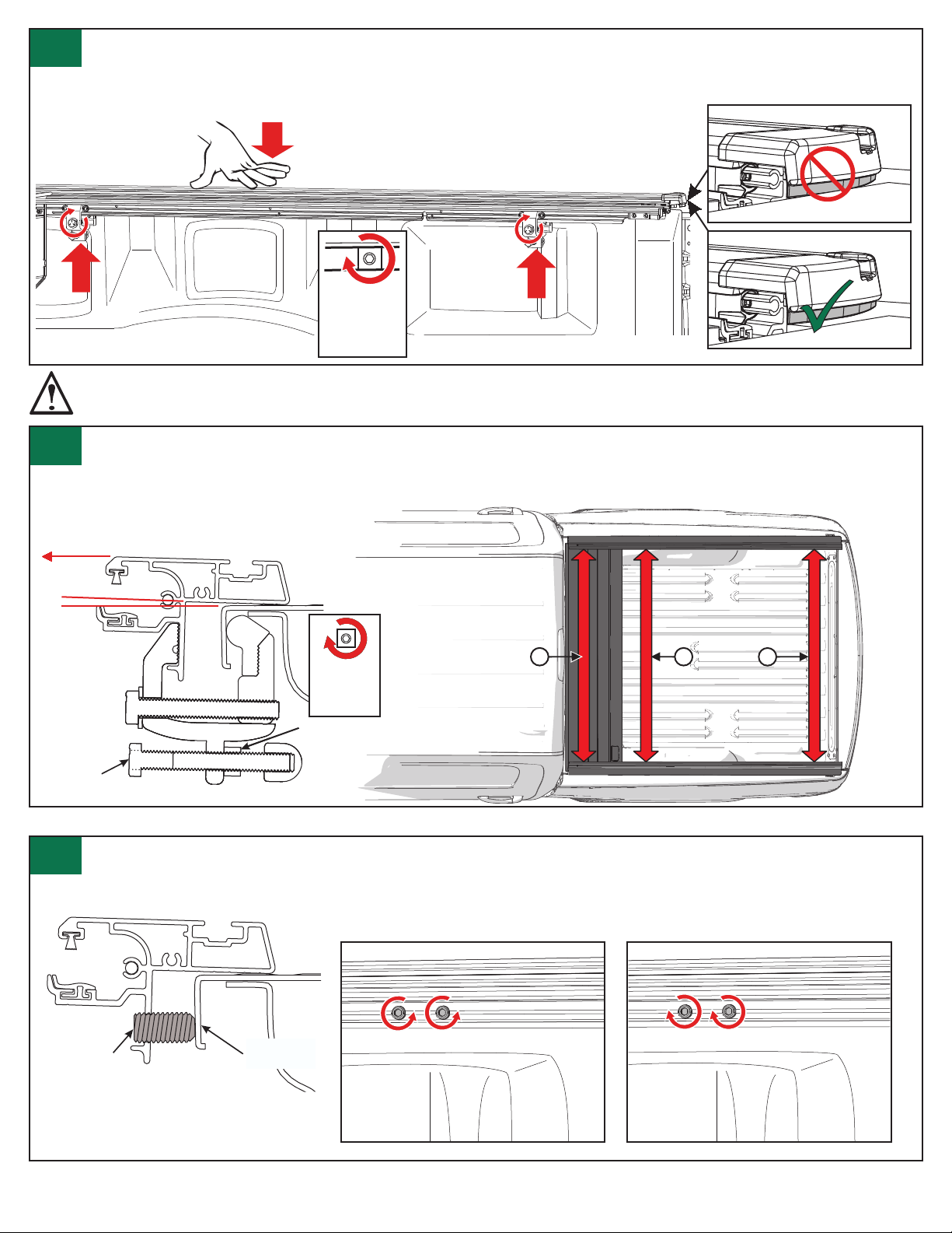
Measure the distance at point A (on top of the cover (C) near the cab). Then measure the distance at points B & C (above
each clamp). They must measure the same +/- 1/16” (1.6 mm) as at point A. It is important that the rails are parallel. If
they are NOT, proceed to step 15. If the measurements are correct, tighten each stand-o bolt on each clamp, so that there
is approximately a 2 degree upward tilt to each rail, as shown in the section below. Then proceed to step 16.
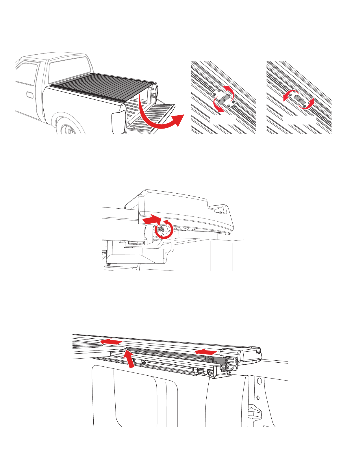
Using a 9/16” wrench, tighten the clamps (G). It is important to push down on the passenger side cover rail (A) while
tightening. The pushing down of the rail will position the rail best to minimimze water intrusion, but Do Not push down too
close to the top of the tailgate because it will interfere with opening and closing of the tailgate. Do this on the driver side cover
rail (B) as well.
13
14
Remove the clamps (G) and turn the white adjustment screws with the 6mm Allen wrench (J) to move the rails.
One complete turn = 1/16” (1.6 mm). Turn both screws. When properly adjusted, reposition and tighten the clamps as in
steps 12-13, then proceed to step 16.
15
Tighten the
clamp bolts
to 6.7 ft/lbs
(9.1 Nm)
BC
A
Measurements are taken
from the top inside of the rails
REAR SECTION
If the rails measure to be too close together,
turn the screws counter clockwise.
If the rails measure to be too far apart,
turn the screws clockwise.
REAR SECTION
Adjustment
screw Truck bed
rail
Retrax • 917S. 46th St., Grand Forks,ND58201 • 800-206-4070 © Retrax Holdings,LLC, 20234000-148 Rev. 9-19-23
Approximately
2°
Stand-o
bolt
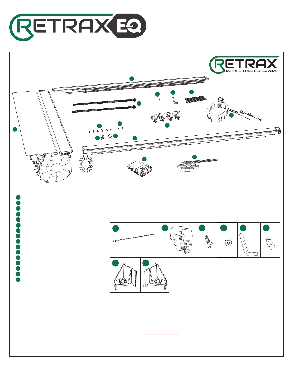
NOTE: Due to variations in vehicle designs, the clamps may fit dierently on your truck than on our test vehicles.
Retrax is not responsible for cover-to-vehicle installation, nor is Retrax liable for any damages resulting from
attachment, installation, or use.
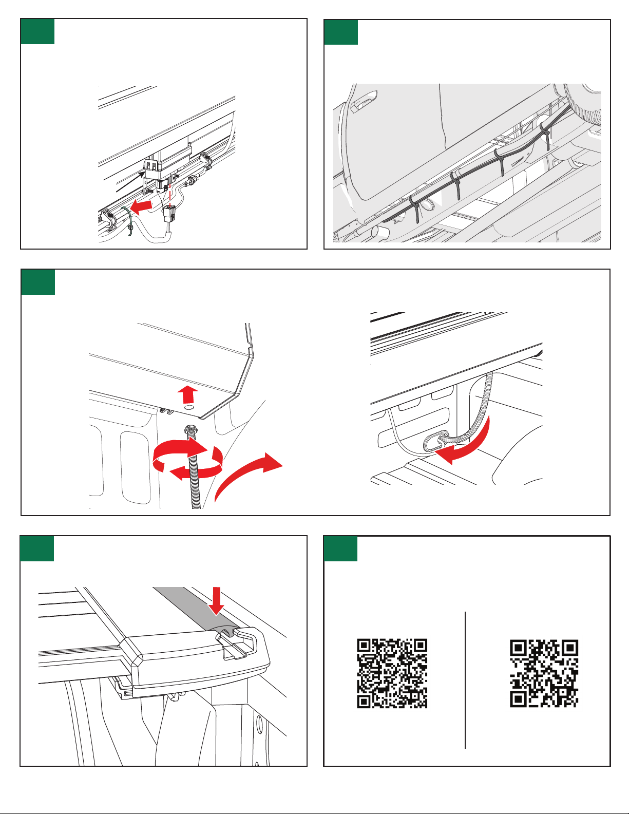
Jam nut
Tighten the
jam nuts to:
6.7 ft-lb
9,1 N-m
Tailgate
Contacting/interfering with the tailgate
Tailgate
Small gap between the end cap & tailgate

Go back underneath the vehicle where the main wiring
harness (E) was zip-tied and pull out all the extra slack in
the harness. Neatly organize and secure the extra slack, using
another zip tie (F). Keep the wires away from moving parts
and exhaust.
Retrax • 917S. 46th St., Grand Forks,ND58201 • 800-206-4070 © Retrax Holdings,LLC, 20234000-148 Rev. 9-19-23
NOTE: For better water drainage, be sure to route the drain
hose out of the truck in the most direct line as possible.
18
Locate the main wiring harness (E) that was installed
previously in steps 5-7. Attach the connector on the wiring
harness to the connector on the cover module on the back of the
cover (C). Once a connection is made, secure the main wiring
harness to the cover (C) with the provided zip tie (F), as shown.
16 17
Cover
Module
Set up the cabin module (L) and T-harness (N).
20
Scan this QR code for a link to your specific
vehicle’s cabin module installation instructions.
Android iOS
Use a scissors or a utility knife to cut the T-slot seal (M)
into two pieces, to the length of the rail minus the end
caps, as shown. Insert the seal into the T-slot on each rail from
the top.
19
Insert a drain tube (D) into the cover on both driver and passenger sides. Rotate to the right; clockwise. The fitting will
click twice when secure. Generally the drain tubes (D) will be routed out through a hole drilled in the factory bed plug,
otherwise a suitable existing hole must be utilized. Alternately, a new hole can be drilled, but take great caution to be aware of
lines and anything else behind where the hole is drilled.

Retrax • 917S. 46th St., Grand Forks,ND58201 • 800-206-4070 © Retrax Holdings,LLC, 20234000-148 Rev. 9-19-23
MANUAL DISCONNECT GUIDE
AUTOMATIC COVER CONNECTION
Disengaged
Engaged
TROUBLESHOOTING
Manual disconnect is operated by first locating the knob on the underside of the cover. Next, rotate the knob 1/4 turn to
disengage the cover from the drive system. While holding the knob in the retracted position, push or pull the cover. This should
allow the cover to move freely. To re-engage the cover to the drive system, push or pull the knob 1/4 turn again and manually
push the cover back into engagement with the drive system. Alternatively, you can follow the steps below for the automatic cover
connection.
To create more of a seal between the cover (C) and the tailgate, back the set screws out. NOTE: It is paramount to move each
set screw the same amount of turns. For example, to bring the cover 1/8” (3.2 mm) closer to the tailgate, back each set screw out
2.5 revolutions. IMPORTANT: Make sure the set screws are not backed out too far, or else the cover will make contact with the
cover stops, which is not advised.
With the cover in the disengaged state, operate the cover electronically, with either the keyfob, keypad, or phone, so that the
drive system brings the carriage in both rails toward the stationary cover. Once the carriages reach the tail slat end of the cover,
the cover will start moving and snap into engagement. Cycle the cover to the fully open or fully closed position to ensure proper
cover engagement.

Retrax • 917S. 46th St., Grand Forks,ND58201 • 800-206-4070 © Retrax Holdings,LLC, 20234000-148 Rev. 9-19-23
HOW TO CALIBRATE YOUR TONNEAU COVER SYSTEM
This step must be performed after the cover is installed, firmware updates are made, and the module programming sequence is
complete.
The calibration process will automatically occur every time the system enters Pairing Mode, or if the power is reset to the Cover
Module.
The calibration process can be performed if at any time the carriages become unaligned with one another.
To calibrate the drive cables, they must traverse the length of the rail in both directions. While in calibration mode, the cover
and/or drive cables will travel at a slower than normal speed.
1. Ensure the cover is disconnected from the carriages in each rail and press the lock button 3X on the OEM key fob to send the
carriages down to the tailgate end of the rails.
While performing the calibration process, the Anti-Pinch feature of the cover will not function.
The calibration process can be completed with or without the cover connected to the drive carriages. It is recommended to perform
the initial calibration cycle with the cover disconnected from the carriages.
a. The calibration process can be initiated from any of the user options; OEM Keyfob, User App, and 5-Button Keypad.
3. As the carriages reach the tail panel of the cover, they will engage and the calibration process will be complete.
STEP 1 STEP 2
2. Once the cables have reached the tailgate end of the rails and have stopped moving, press the unlock button 3X on the OEM fob
to bring the carriages all the way back to the cab end of the cover.
Tailgate
Cab

Retrax • 917S. 46th St., Grand Forks,ND58201 • 800-206-4070 © Retrax Holdings,LLC, 20234000-148 Rev. 9-19-23
All large and heavy cargo must be secured by straps.
NEVER allow children or pets to occupy the truck bed while the cover is closed.
The cover is not airtight. Special care is required to keep cargo clean and dry.
Tonneau covers won’t prevent theft of contents inside the truck box.
CLOSE
COVER CARE AND MAINTENANCE
Clean with mild automotive soap and water only. Do NOT use any strong chemicals or cleaners.
Do NOT wax your Retrax cover. The weather-stripping on your cover may absorb soapy residue from a car wash, so we
recommend wiping down the inside of your rails from time to time.
It is recommended that you periodically check that the cover is securely attached to your truck bed. Inspect the clamps and front
mounting bolts to ensure they were properly installed and have not come loose or knocked out of adjustment during operation.
Covers that are used with high frequency or that are subject to the vibrations and impact from rough roadways can cause the
cover to require adjustment.
USE
USE OF COVER WITH OEM KEY FOB
Press the lock button three times to close.
Press the unlock button three times to open.
SAFETY INSTRUCTIONS
Do NOT tow your vehicle from the rear with the cover on your vehicle. If towing from the rear is required, the cover MUST be
removed from the vehicle and properly stored.
ACCESS
CODE
#####
800-206-4070
UNLOCKALL DOORS: Press the 3/4 key within
5 seconds of entering the 5-digit access code.
LOCKALLDOORS: Press and hold 7/8 and 9/0
buttons simultaneously for at least 2 seconds.
OPEN COVER: Press 1/2 key within 5 seconds of
entering the 5-digit access code.
CLOSE COVER: Press 9/0 key within 5 seconds of
entering the 5-digit access code.
OPERATE THE TAILGATE:*Press the 5/6 key within
5 seconds of entering the 5-digit access code.
*Powered tailgates only.
USE OF COVER WITH PHONE APP
Press the open icon to open the cover.
Press the close icon to close the cover.
5-BUTTON KEYPAD INSTRUCTIONS (OPTIONAL)
CLOSE
OPEN
OPEN
To enter “Cinch” mode to secure loose cargo in place against the tailgate, press the lock button three times. The cover will meet
resistance and retract a couple inches. Press the lock button three times again and the cover will retract and cinch the object in
place.
Android iOS
Scan this QR code for a
link to your specific
vehicle’s User App.
If the vehicle is driven frequently in dusty conditions, it is recommended to periodically clean dirt and dust from inside the rails
and spiral canister with a wet towel. To further improve cover performance, it is acceptable to apply a thin film of plastics safe,
silicon based lubricant.

Retrax • 917S. 46th St., Grand Forks,ND58201 • 800-206-4070 © Retrax Holdings,LLC, 20234000-148 Rev. 9-19-23
When calling or emailing,
please be prepared to
reference your part number
and serial number. The serial
number is located under the
cover next to the lock
assembly on the tailgate
extrusion. The serial number
is 8 - 14 digits and may or may
not include a letter in it.
Limited Warranty
WARRANTY COVERAGE
This truck bed cover is warrantied against defects in materials or workmanship as follows. This warranty is void if the product
has been damaged in an accident, or due to neglect, unforeseeable use, improper installation, improper servicing, or other
cause not arising out of defects in material or workmanship.
WARRANTY IS NOT TRANSFERABLE
The warranty is to the initial consumer purchasing the truck bed cover and it is not transferrable to a subsequent end user. Proof
of purchase may be required to enforce these warranty rights.
WARRANTY CONDITIONS
Failure to follow these care and use instructions will void the warranty::
• Clean with mild automotive soap and water only. Do not use any strong chemicals or cleaners. Lubrication
of the rails or sealed ball bearings will void the warranty.
• Cargo must be secured at all points when the vehicle is in motion. Failure to adequately secure the cover or
tether strap can result in damage and will void the warranty.
• Check all clamps and retention mechanisms for tightness after a week of driving following installation (or
re-installation) ofthe cover and periodically thereafter.
• Before opening, the cover must be free ofall foreign materials including snow and ice.
• Do NOT tow your vehicle from the rear with the cover on your vehicle. If towing from the rear is required,
the cover MUST be removed from the vehicle and properly stored.
WARRANTY PERFORMANCE
If all warranty conditions are met, a defective truck bed cover or hardware component will either be repaired or replaced (at our
option). We reserve the right, for any warranty, to substitute a newer model or bed cover having a similar form and function, to
oer a warranty discount on an entire replacement system, and/or provide remedies other than those mentioned in this document.
WARRANTY RETURN
A Return Material Authorization number must be obtained from our Customer Service Department prior to returning any product.
We may require the original item to be returned postage prepaid for final determination. Shipping charges will apply for any repair
or replacement. Other than postage or shipping charges, no charge will be made for repair or replacement under this warranty.
This warranty gives you specific legal rights. As a consumer, you may also have additional rights and remedies under the laws
of your state.
The truck bed covers carries a limited warranty for five (5) years from the original dateofpurchase, subject to the terms below.
REGISTER
YOUR
WARRANTY
ONLINE
WARRANTY REGISTRATION
Warranty registration must be on file and/or proof of original purchase (detailed and dated receipt) required for warranty to be
eective.
Register online at https://retrax.com/warranty-registration.
Other manuals for EQ
1
Table of contents
Other Retrax Automobile Accessories manuals
Popular Automobile Accessories manuals by other brands

Mobidick
Mobidick SuperTooth Light manual

Whelen Engineering Company
Whelen Engineering Company Traffic Advisor TA8852H installation guide

ULTIMATE SPEED
ULTIMATE SPEED 113032 Assembly and Safety Advice

Metra Electronics
Metra Electronics 95-6513B installation instructions

D-Flector
D-Flector D600 installation guide

GMC
GMC A2D-GM2 installation guide

Ranger design
Ranger design 1530-MM installation guide

Safe Fleet
Safe Fleet Prime Design PCR-6000 Assembly instructions

Metra Electronics
Metra Electronics 99-8218 installation instructions

BrandMotion
BrandMotion F Series installation instructions

Nokia
Nokia CARK-91US installation guide

Sanji
Sanji EasyVOX manual