REVELL Ultima Sub30 User manual

®
Revel
®
Ultima™Sub 30

WARNING: TO REDUCE THE RISK OF FIRE OR ELECTRIC SHOCK,
DO NOT EXPOSE THIS PRODUCT TO RAIN OR MOISTURE.
REVEL ULTIMA SUB 30
Owner’s Manual
2
CAUTION
RISK OF ELECTRIC SHOCK
DO NOT OPEN
CAUTION: TO REDUCE THE RISK OF ELECTRIC SHOCK,
DO NOT REMOVE COVER (OR BACK).
NO USER-SERVICEABLE PARTS INSIDE.
REFER SERVICING TO QUALIFIED SERVICE PERSONNEL.
The lightning flash with arrowhead symbol, within an equi-
lateral triangle, is intended to alert the user to the presence of
uninsulated “dangerous voltage” within the product’s enclosure
that may be of sufficient magnitude to constitute a risk of elec-
tric shock to persons.
The exclamation point within an equilateral triangle is
intended to alert the user to the presence of important operat-
ing and maintenance (servicing) instructions in the literature
accompanying the product.

IMPORTANT SAFETY INSTRUCTIONS
Please read all instructions carefully and completely before
operating your REVEL®ULTIMA™SUB 30 powered subwoofer
system.
1. Always disconnect ac power before connecting or disconnecting
any cables, or when cleaning any component.
2. This product uses a three-conductor power cord, which
includes an earth-ground connection. To prevent shock hazard,
always connect it directly to a grounded outlet.
3. Never use any ac extension cord with this product.
4. Never use flammable or combustible chemicals for cleaning
audio components.
5. Never operate this product with any covers removed.
6. Never wet the inside of this product with any liquid.
7. Never pour or spill liquids directly onto this unit.
8. Never block air flow through ventilation slots or heatsinks.
9. Never bypass any fuse.
10. Never replace any fuse with a value or type other than specified.
11. Never attempt to repair this product yourself. If a problem
occurs, contact your Revel retailer.
12. Never expose this unit to extremely high or low temperatures.
13. Never operate this product in an explosive atmosphere.
14. Always keep electrical equipment out of the reach of children.
15. Always consider manual and safety instructions in any end
use application.
Before connecting this product to an ac power line, verify the voltage
shown in the voltage selector switch (on the rear panel) matches the ac
line voltage where the unit will be operated. Never attempt to operate
or connect this product to an ac line voltage that is different from the
one indicated in the voltage selector switch. Using a different setting
can damage the unit and will void your warranty!
REVEL ULTIMA SUB 30
Owner’s Manual 3
WARNING

TABLE OF CONTENTS
INTRODUCTION.........................................................5
ABOUT THE MANUAL AND WARRANTY...................................................5
DESCRIPTION............................................................6
SUBWOOFER ......................................................................................6
AUXILIARY BASS RADIATOR ......................................................................7
ELECTRONICS.....................................................................................7
CABINET.............................................................................................7
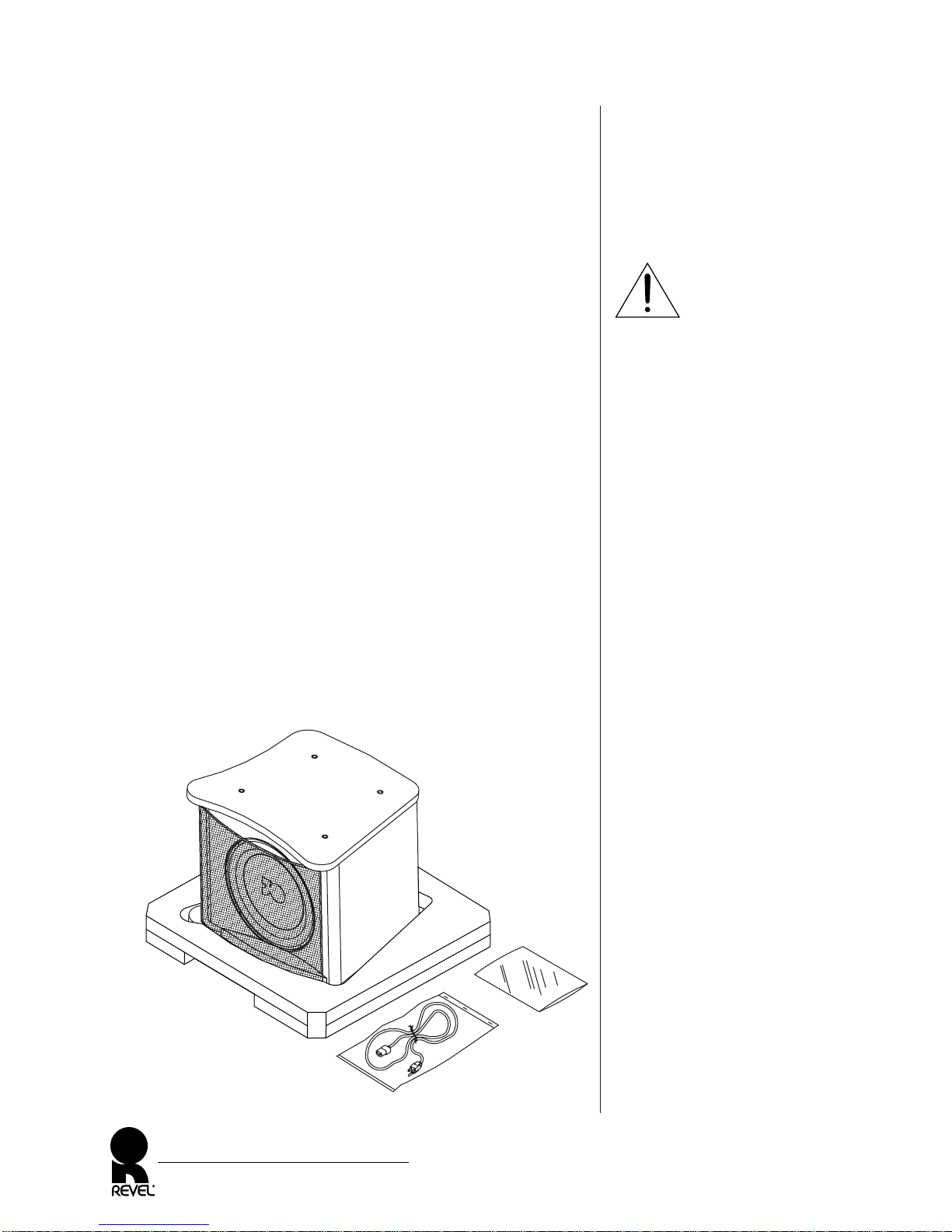
UNPACKING..............................................................8
INSPECTING THE REVEL ULTIMA SUB 30...............................................9
ADJUSTING THE SPIKE FEET ................................................................9
REAR PANEL LAYOUT...............................................10
CONNECTIONS........................................................12
APPLICATIONS.........................................................13
MULTI-CHANNEL CONTROLLER WITH CROSSOVER AND
A REVEL ULTIMA SUB 30 ................................................................14
MULTI-CHANNEL CONTROLLER WITH CROSSOVER AND
MULTIPLE REVEL ULTIMA SUB 30 SUBWOOFERS..............................15
MULTI-CHANNEL CONTROLLER AND
A REVEL ULTIMA SUB 30 WITH CROSSOVER ....................................16
SURROUND-SOUND PROCESSOR WITH CROSSOVER AND
REVEL ULTIMA SUB 30 SUBWOOFERS IN STEREO.............................17
MULTI-CHANNEL CONTROLLER AND REVEL ULTIMA SUB 30
SUBWOOFERS WITH CROSSOVERS IN STEREO.................................. 18
STEREO POWER AMPLIFIER AND
A REVEL ULTIMA SUB 30 WITH CROSSOVER....................................19
MULTI-CHANNEL CONTROLLER AND MULTIPLE REVEL ULTIMA SUB 30
SUBWOOFERS WITH CROSSOVERS.....................................................20
STEREO POWER AMPLIFIER AND
A REVEL ULTIMA SUB 30 WITHOUT HIGH-PASS CROSSOVER.............21
SYSTEM OPTIMIZATION............................................22
PLACEMENT OVERVIEW.....................................................................22
GENERAL PLACEMENT GUIDELINES....................................................23
SOUND MEASUREMENT GUIDELINES...................................................25
SELECTING CROSSOVER POINTS AND SLOPES ....................................26
CABINET CARE........................................................27
TROUBLESHOOTING ................................................27
OBTAINING SERVICE................................................28
SPECIFICATIONS......................................................29
SUBWOOFER ....................................................................................29
AMPLIFIER........................................................................................29
REVEL ULTIMA SUB 30
Owner’s Manual
4

INTRODUCTION
The REVEL ULTIMA SUB 30 powered subwoofer system
combines an outstanding 15" subwoofer with a 1,000-watt (rms)
amplifier, capable of 1,400-watt peaks, for stupendous bass output.
Moreover, the REVEL ULTIMA SUB 30’s stylistic form and
compact size provide a surprisingly prodigious output and unprece-
dented tonal accuracy, even in the deepest octaves. Impressive fea-
tures include three independent parametric equalizers and an
adjustable crossover so you can customize and adapt this system for
a wide variety of applications.
This tremendous flexibility results in superb integration with any
Revel loudspeakers, or even with other manufacturers’ speakers.
ABOUT THE MANUAL AND WARRANTY
To begin enjoying your REVEL ULTIMA SUB 30, first read and
then perform the instructions in this owner’s manual. Maximum
performance is dependent on following all instructions described
here, as well as those found in the owner’s manuals of
associated components in your audio system. Save these instructions
for future reference.
The REVEL ULTIMA SUB 30 is covered by a limited warranty, so
save the bill of sale to protect your purchase and aid in any service-
related questions.
REVEL ULTIMA SUB 30
Owner’s Manual 5
Figure 1.The REVEL
ULTIMA SUB 30
powered subwoofer system.

Figure 2.Transducer and connec-
tion locations for the REVEL
ULTIMA SUB 30 powered
subwoofer system.
DESCRIPTION
The REVEL ULTIMA SUB 30 powered subwoofer system features
a unique transducer that combines brute-force capabilities unprece-
dented in home loudspeakers with a new level of low frequency
nuance and refinement. Combined with the huge internal power
capability, the result is a new standard of bass performance and
adaptability for home entertainment systems.
SUBWOOFER
To ensure uncompressed dynamic range, each REVEL ULTIMA
SUB 30 features a subwoofer with the following attributes:
•A3-inch (76 mm) diameter, four-layer voice coil with 23-gauge
copper wire is wound on a dual-laminated Kapton®former for
extraordinary power handling and freedom from compression.
•Extremely long-throw voice coil is capable of 2.5 inches (64 mm)
of peak-to-peak linear excursion, and 3 inches (76 mm) of maxi-
mum excursion for uncompressed reproduction of deep sustained
bass notes.
•Amassive, 130-ounce (3.7 kg) magnet system produces
1.4 tesla of flux in the gap.
•Ultra-rigid Kevlar®pulp and alloy composite cone with an
inverted metal dome operate as a perfect piston under all
reproduction conditions.
•Modulation rings and a machined “T” pole-piece for extremely
low distortion.
•The heavy-wall, cast-aluminum frame maintains alignment
between the magnet structure and the moving elements, while
offering excellent rigidity to eliminate basket resonances.
REVEL ULTIMA SUB 30
Owner’s Manual
6
3O
REVEL ULTIMA SUB 30
Front (without grille) REVEL ULTIMA SUB 30
Rear

AUXILIARY BASS RADIATOR
Each REVEL ULTIMA SUB 30 also includes an auxiliary bass radi-
ator (on the cabinet bottom) with the following attributes:
•15-inch (381 mm) cast frame
•Produces up to 2.2-inch (55.9 mm) peak-to-peak excursion that
serves to dramatically increase output at the lowest frequencies,
while reducing distortion
ELECTRONICS
Each REVEL ULTIMA SUB 30 contains an electronics section with
the following attributes:
•An extremely low-distortion, 1,000-watt (rms) amplifier with
1,400-watt burst capability produces peak bass output up to
126 dB at 30 Hz in a standard listening room.
•Inaudible protection circuit to guard against overload.
•Three independent parametric equalizers, each with variable fre-
quency, bandwidth, and level controls, to allow you to precisely
tailor the room response and tame unwieldy acoustic anomalies.
•2-way crossover with variable frequency and selectable slopes
allows ideal response matching with other audio components.
NOTE: For details on controls and connections, see “Rear Panel Layout”
on page 10.
CABINET
The REVEL ULTIMA SUB 30’s cabinet is constructed of 1-inch
(25 mm) thick MDF wall, optimally designed and internally braced
with the aid of laser interferometry, for unshakable performance.
REVEL ULTIMA SUB 30
Owner’s Manual 7

Figure 3.The REVEL ULTIMA
SUB 30 with its inner packing
materials.
UNPACKING
To avoid personal injury and possible product damage, we strongly
urge you to enlist additional help before unpacking the REVEL
ULTIMA SUB 30. Also, be sure to observe the following precau-
tions and procedures:
•Do not attempt to lift the product from its packing carton
alone. To unpack a product properly, at least two strong people
will be needed.
•To avoid injury, use extreme care during unpacking.
•Do not lift a product while bending from the waist.
•Always stand as straight as possible and use leg muscles to lift a
product.
1. At the final placement choice (see System Optimization on
page 22), set the packaged REVEL ULTIMA SUB 30 on a rug
or other soft material in the upright position. Open the top
flaps and set aside the cardboard filler. It contains the power
cord, the owner’s manual, test CD, and 3 ⁄ 16" hex key.
2. With the top flaps folded back, roll the carton over onto its
exposed end pad. Open the bottom flaps and fold them back.
Remove the other exposed end pad.
3. Lift the carton off the unit and set it aside, being careful not to
damage the contents (see Figure 3 below).
REVEL ULTIMA SUB 30
Owner’s Manual
8
IMPORTANT
End Pad
Warranty Card,
Owner’s Manual,
Test CD, and
3 ⁄ 16" Hex Key
Power Cord

INSPECTING THE REVEL ULTIMA SUB 30
After unpacking, carefully inspect the REVEL ULTIMA SUB 30 for
possible damage due to shipping. If you discover any damage,
immediately contact your Revel dealer for further assistance. Keep
all packing materials for future shipping. In the unlikely event a
product will need repair, Revel will only accept a unit in its origi-
nal shipping carton. Using any other packing materials may result
in damage to the product and is not covered by the warranty. See
Obtaining Service on page 28 for additional details.
ADJUSTING THE SPIKE FEET
NOTE: The four spike feet are already set at the factory for a level hard
floor. However, if the floor is uneven or an extra-thick carpet is in place,
you’ll need to adjust them further to compensate.
ADJUSTMENT FOR UNEVEN HARD FLOORS
1. Set the unit in its desired location. Turn the REVEL ULTIMA
SUB 30 onto its feet. Remove the end pad.
2. Loosen the locking ring of the foot that is not in contact with
floor by rotating it counter-clockwise.
3. Adjust the foot until it firmly touches the floor. Make sure
there is about a 1 ⁄ 4" clearance between the bottom edges of
the side panels and the floor. Tighten the locking ring by
rotating it clockwise.
ADJUSTMENT FOR CARPETED FLOORS
1. Remove the spike foot covers by turning them counter-clockwise,
and then store them for possible future use.
2. Loosen each locking ring by rotating it counter-clockwise.
Adjust each spike to extend past the thickness of the carpet
and add about a 1 ⁄ 4" for clearance.
3. Set the unit in its desired location. Turn the REVEL ULTIMA
SUB 30 onto its spikes. Remove the end pad.
4. Verify that there is about a 1 ⁄ 4" clearance between the bottom
edges of the side panels and the carpeted floor. If not, turn the
unit back on its side and repeat steps 2 to 4 as necessary.
5. Tighten each locking ring by rotating it clockwise.Turn the
REVEL ULTIMA SUB 30 onto its spikes and try rocking the
unit to make sure all spikes contact the floor.
If not, adjust the spikes as necessary.
REVEL ULTIMA SUB 30
Owner’s Manual 9

Figure 4.The REVEL
ULTIMA SUB 30’s rear panel
layout shows locations of controls,
as well as audio
and power connectors.
REAR PANEL LAYOUT
❶EQ ALL: Use this control to bypass all three parametric equalizers
for an audible demonstration of the equalization effect. It can
also prove valuable during the equalization process. For example,
to hear the effect of only one or two of the equalizers, set the
level controls of the remaining equalizer(s) at the “12 o’clock”
position.
❷EQ 1~ EQ 3: The three parametric equalizers include variable
controls for Frequency, Bandwidth, and Level. Use these controls
to modify the frequency response at three points, adjustable
from 18 to 80 Hz, across a bandwidth from 0.1 to 1.0 octaves,
with level boost up to 6 dB or level cut to -14 dB.
REVEL ULTIMA SUB 30
Owner’s Manual
10
3O

❸CONTOUR: This control provides access to two different overall
system responses: Music or Film. Selecting Music does not alter
the subwoofer's response. Selecting Film provides a tailored
boost at the lowest frequencies that many find desirable for film
sound reproduction.The response contour can be selected
either manually by changing the switch position to Music or
Film, or automatically by selecting External Trigger to accept a
trigger voltage from an external device, such as a multi-channel
controller, applied to the TRIGGER Music/Film input terminals.
❹LOW PASS/HIGH PASS:The LOW PASS filter has In/Out and
24/48 dB slope switches, and variable controls for Frequency,
Phase, and Level.The HIGH PASS filter is always on and has a
variable Frequency control and 12/24 dB slope switch. Use the
filter controls to precisely set a two-way crossover point from 30
to 80 Hz, with symmetrical 24 dB slopes or asymmetrical 24/12
or 48/12 dB slopes, and low-pass phase shift from 0 to 180
degrees. Use the LOW PASS Level control to set the subwoofer
system’s output level. When using a multi-channel controller,
the LOW PASS Level control is normally set to the “0” position.
❺INPUT: Use stereo XLR (balanced) connectors or RCA (unbal-
anced) jacks to connect from preamplifier outputs, or front
outputs of a multi-channel decoder. Both inputs are 0 dBv
(nominal)/+20 dBv (maximum). The XLR input is pin 2 high.
❻AUX OUTPUT: Use stereo XLR (balanced) connectors or RCA
(unbalanced) jacks to loop input audio signals to additional
REVEL ULTIMA SUB 30 subwoofers (if present). Both out-
puts are 0 dBv (nominal)/+20 dBv (maximum).The XLR out-
put is pin 2 high.
❼HIGH PASS OUTPUT: Use stereo XLR (balanced) connectors or
RCA (unbalanced) jacks for (high-pass) connection to the main
amplifier’s left input. Both outputs are 0 dBv (nominal)/
+20 dBv (maximum). The XLR output is pin 2 high.
❽POWER ON MODE: Select Auto to turn on automatic power
when the POWER switch is set to ON. Internal sense circuits will
continually detect the presence of audio signals and fully turn
on the power supply when needed. After some time, when
audio is no longer present, the same circuits will instruct the
power supply to enter the standby mode to conserve energy.
Or select 12V Trigger to turn on/off power via a remote 12 Vdc
supply. A 12-volt trigger voltage is available from some multi-
channel audio/video controllers, as well as from integrated
remote control systems. Continued on the next page...
REVEL ULTIMA SUB 30
Owner’s Manual 11

REAR PANEL LAYOUT (Continued)
❾TRIGGER Power and Music/Film: When POWER ON MODE is set
to 12V Trigger, applying a steady 12 Vdc voltage to the TRIGGER
Power terminals will turn on the REVEL ULTIMA SUB 30.
When CONTOUR is set to External Trigger, applying a steady
12 Vdc voltage to the TRIGGER Music/Film terminals will auto-
matically select the Film contour response. A 12-volt trigger
voltage is available from some multi-channel audio/video con-
trollers, as well as from integrated remote control systems.
➓POWER ON/OFF Switch, AC Voltage Selector, and Fused Power
Connector for (enclosed) Detachable IEC Power Cord:
If needed, replace the fuse with same type, as follows:
• For 115 Vac @ 60 Hz, use a T6.3AL, 250V slow-blow fuse.
• For 230 Vac @ 50 Hz, use a T6.3AL, 250V slow-blow fuse.
The ac voltage selector sets the subwoofer system for 115 or 230Vac
operation.Verify the switch setting matches the ac line voltage where
the unit will be operated.
RISK OF ELECTRICAL SHOCK! Only use a qualified
technician to change the ac voltage setting. Make sure the subwoofer
system is turned off and unplugged from the
ac line prior to changing the switch.
CONNECTIONS
Audio interconnection to your main amplifier or home theater
controller can be any combination of unbalanced or balanced
terminations, with full balanced connections offering the best
noise suppression.
Please read the Applications section (starting on the next page)
before proceeding with the actual connections. For clarity, power
connections are not shown. Also, be sure to observe the following:
•Turn off all audio system power before making any connections.
•Read the owner’s manuals that were included with your audio
components to confirm their connection procedures.
REVEL ULTIMA SUB 30
Owner’s Manual
12
IMPORTANT
WARNING

APPLICATIONS
The REVEL ULTIMA SUB 30 powered subwoofer system is very
flexible and can be configured for use in various applications with
associated external components.
As an aid, use the chart below to quickly locate an application with
configuration characteristics that is closest to your desired system.
The most common ones are Figures 5 and 6 (on pages 14 and 15),
where one or more REVEL ULTIMA SUB 30 subwoofers are
connected to a multi-channel controller and use the controller’s
internal crossover.
NOTE: If your multi-channel controller has both SUB and LFE
Outputs, use the SUB Output for the subwoofer system(s) connections.
NOTE:When using the multi-channel controller’s crossover, the crossover
frequency is typically set to 80 Hz for the center, surrounds and back
channels. See “Selecting Crossover Points And Slopes” on page 26.
REVEL ULTIMA SUB 30
Owner’s Manual 13
ULTIMA SUB 30 CONFIGURATION CHARACTERISTICS
APPLICATION
# of Channels Crossover on # of Subs.
High-Pass Out
(Figure #, page #) 2 Multi. Contrl. Sub. 1 Multi. Yes No
Figure 5, page 14 ✔✔ ✔ ✔
Figure 6, page 15 ✔✔ ✔ ✔
Figure 7, page 16 ✔✔✔✔
Figure 8, page 17 ✔✔ ✔ ✔
Figure 9, page 18 ✔✔✔✔
Figure 10, page 19 ✔✔✔✔
Figure 11, page 20 ✔✔✔✔
Figure 12, page 21 ✔✔✔✔

Figure 5. How to connect
the REVEL ULTIMA
SUB 30 to a home
theater multi-channel controller
using the controller’s crossover.
APPLICATIONS (Continued)
MULTI-CHANNEL CONTROLLER WITH CROSSOVER
AND A REVEL ULTIMA SUB 30
In this application, the REVEL ULTIMA SUB 30’s internal filter
is bypassed and the multi-channel controller’s crossover is used
instead, as shown in Figure 5.
REVEL ULTIMA SUB 30
Owner’s Manual
14
ULTIMA SUB 30 Rear Panel (split view)
*To SUB/LFE Output
(if using optional Y-adapter)
Use L or R Input and Increase
Low Pass Level to +6 dB;
Multi-Channel Controller (Decoder)
(rear)
Left Output
FRONT/MAIN
Right Output
Left Output
REAR
Right Output
Left Output
SURROUND/SIDE
Right Output
CENTER Output
SUB/LFE Output
NOTE: Set Controller to
SUB “On” and all speakers
to cross over (typically)
at 80 Hz. Main Amplifier
(rear)
To Main Speakers
Left Input
Left Right
Right Input
or or
or
or or

Figure 6. How to connect
multiple REVEL ULTIMA SUB
30 subwoofers to a home
theater multi-channel controller
using the controller’s crossover.
MULTI-CHANNEL CONTROLLER WITH CROSSOVER
AND MULTIPLE REVEL ULTIMA SUB 30 SUB-
WOOFERS
Multiple REVEL ULTIMA SUB 30 subwoofers can be connected
in a “daisy-chain” with a multi-channel controller (using its
crossover) and power amplifier, as shown in Figure 6.
REVEL ULTIMA SUB 30
Owner’s Manual 15
#1 ULTIMA SUB 30 Rear Panel
(split view)
#2 ULTIMA SUB 30 Rear Panel
(split view)
Use L or R Input and Increase
Low Pass Level to +6 dB;
*Or Use Optional
Y-adapter, If Desired.
Main Amplifier
(rear)
To Main Speakers
Left Input
Left Right
Right Input
Multi-Channel Controller (Decoder)
(rear)
Left Output
FRONT/MAIN
Right Output
Left Output
REAR
Right Output
Left Output
SURROUND/SIDE
Right Output
CENTER Output
SUB/LFE Output
NOTE: Set Controller to SUB
“On” and all speakers to cross
over (typically) at 80 Hz.
or or
or
RCA cables
to #2 sub.
INPUT
or
(Optional)
RCA cables
to #3 sub.
INPUT
(Optional)
XLR cables
to #3 sub.
INPUT
or
RCA cables
to #1 sub.
AUX OUTPUT
or
or
or
*To SUB/LFE Output
(if using optional Y-adapter)
*To SUB/LFE Output
(if using optional Y-adapter)

Figure 7. How to connect
the REVEL ULTIMA
SUB 30 to a home theater
multi-channel controller using
the subwoofer’s internal
crossover.
APPLICATIONS (Continued)
MULTI-CHANNEL CONTROLLER AND A REVEL ULTIMA
SUB 30 WITH CROSSOVER
In this application, the REVEL ULTIMA SUB 30’s
internal crossover is used to interconnect a home theater
multi-channel controller, as shown in Figure 7.
REVEL ULTIMA SUB 30
Owner’s Manual
16
ULTIMA SUB 30 Rear Panel (split view)
Multi-Channel Controller (Decoder)
(rear)
Left Output
FRONT/MAIN
Right Output
Left Output
REAR
Right Output
Left Output
SURROUND/SIDE
Right Output
CENTER Output
SUB/LFE Output
NOTE: Set Controller outputs to
full-range L/R Front and no SUB.
If applicable, set all other channels
to pass 80 Hz (typically) and above.
Below 80 Hz (typically), signals will
route to the ULTIMA SUB 30.
Main Amplifier
(rear)
To Main Speakers
Left Input
Left Right
Right Input
or
or
or or

Figure 8. How to connect two
REVEL ULTIMA SUB 30
subwoofers to a Surround-Sound
Processor using the processor’s
internal crossover for stereo bass.
SURROUND-SOUND PROCESSOR WITH CROSSOVER
AND REVEL ULTIMA SUB 30 SPEAKERS IN STEREO
Two REVEL ULTIMA SUB 30 speakers can be used for stereo
bass with a surround-sound processor after it is configured for left
and right subwoofer outputs, as shown in Figure 8.
REVEL ULTIMA SUB 30
Owner’s Manual 17
Right ULTIMA SUB 30 Rear Panel
(split view)
Left ULTIMA SUB 30 Rear Panel
(split view)
Surround-Sound Processor
(rear)
NOTE: On some Surround-Sound Processors,
the SUBWOOFER Outputs may be labeled AUX.
Set the crossover to route low-frequency signals
(typically below 80 Hz) to the SUBWOOFER or
AUX outputs.
Left Output
FRONT/MAIN
Right Output
Left Output
REAR
Right Output
Left Output
SUBWOOFER
Right Output
Left Output
SURROUND/SIDE
Right Output
CENTER Output
SUB/LFE Output
or
or

Figure 9. How to connect
two REVEL ULTIMA SUB 30
subwoofers to a home theater
multi-channel controller using
the subwoofers’ internal
crossovers.
APPLICATIONS (Continued)
MULTI-CHANNEL CONTROLLER
AND REVEL ULTIMA
SUB 30 SUBWOOFERS WITH CROSSOVERS IN
STEREO
Using internal crossovers, two REVEL ULTIMA SUB 30 subwoofers
can also be set up for stereo bass with a multi-channel controller, as
shown in Figure 9.
REVEL ULTIMA SUB 30
Owner’s Manual
18
Right ULTIMA SUB 30 Rear Panel
(split view)
Left ULTIMA SUB 30 Rear Panel
(split view)
Main Amplifier
(rear)
To Main Speakers
Left Input
Left Right
Right Input
Multi-Channel Controller (Decoder)
(rear)
Left Output
FRONT/MAIN
Right Output
Left Output
REAR
Right Output
Left Output
SURROUND/SIDE
Right Output
CENTER Output
SUB/LFE Output
NOTE: Set Controller outputs to
full-range L/R Front and no SUB.
If applicable, set all other channels
to pass 80 Hz (typically) and above.
Below 80 Hz (typically), signals will
route to the ULTIMA SUB 30 subwoofers. or or
or
or
(Optional)
To SUB/LFE Output
(use Y-adapter)
(Optional)
To SUB/LFE Output
(use Y-adapter)

Figure 10. How to connect
the REVEL ULTIMA SUB 30
(with its internal high-pass
crossover) between a stereo
preamplifier and main power
amplifier.
STEREO POWER AMPLIFIER AND A REVEL SUB 30
WITH CROSSOVER
The most common two-channel application is interconnecting the
REVEL ULTIMA SUB 30 between a stereo preamplifier and the
main power amplifier, as shown in Figure 10.
REVEL ULTIMA SUB 30
Owner’s Manual 19
ULTIMA SUB 30 Rear Panel
(split view)
Preamplifier
(rear)
Left Output Right Output
Main Amplifier
(rear)
To Main Speakers
Left Input
Left Right
Right Input
or or
oror

Figure 11. How to connect
multiple REVEL ULTIMA SUB
30 subwoofers to a home
theater multi-channel controller
using the subwoofers’ crossovers.
APPLICATIONS (Continued)
MULTI-CHANNEL CONTROLLER
AND MULTIPLE REVEL
ULTIMA SUB 30 SUBWOOFERS WITH CROSSOVERS
Multiple REVEL ULTIMA SUB 30 subwoofers (using their inter-
nal crossovers) can be connected in a “daisy-chain” with a multi-
channel controller and power amplifier, as shown in Figure 11.
REVEL ULTIMA SUB 30
Owner’s Manual
20
#1 ULTIMA SUB 30 Rear Panel
(split view)
#2 ULTIMA SUB 30 Rear Panel
(split view)
Multi-Channel Controller (Decoder)
(rear)
Left Output
FRONT/MAIN
Right Output
Left Output
REAR
Right Output
Left Output
SURROUND/SIDE
Right Output
CENTER Output
SUB/LFE Output
NOTE: Set Controller outputs to
full-range L/R Front and no SUB.
If applicable, set all other channels
to pass 80 Hz (typically) and above.
Below 80 Hz (typically), signals will
route to the ULTIMA SUB 30.
Main Amplifier
(rear)
To Main Speakers
Left Input
Left Right
Right Input
or
or
or or
or
(Optional)
RCA cables
to #3 sub.
INPUT
or
RCA cables
to #2 sub.
INPUT
(Optional)
XLR cables
to #3 sub.
INPUT
XLR cables
to #2 sub.
INPUT
On all subs.
XLR cables
from #1 sub.
AUX OUTPUT
or
RCA cables
from #1 sub.
AUX OUTPUT
Table of contents
Other REVELL Subwoofer manuals

REVELL
REVELL Performa B15a User manual

REVELL
REVELL Ultima Sub15 User manual

REVELL
REVELL Concerta B120 User manual

REVELL
REVELL B28w User manual

REVELL
REVELL Performa B15 User manual

REVELL
REVELL Concerta B1 User manual

REVELL
REVELL Concerta B12 User manual

REVELL
REVELL CONCERTA 2 B10 User manual

REVELL
REVELL B8 User manual

REVELL
REVELL Performa3 B112 User manual