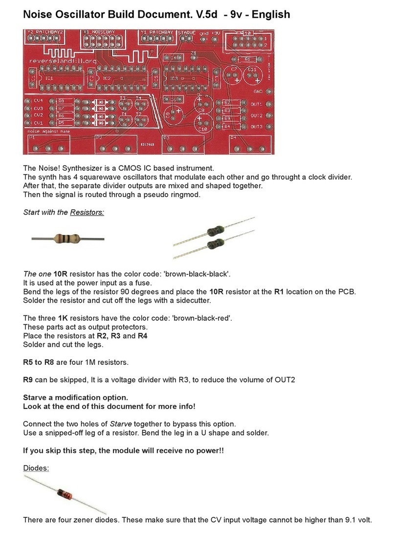
On the PCB you can see this markin as well. Place the 16-pin IC socket in IC2.
Flip over the PCB and solder two le s, on in the upper row, one in the lower row, dia onally from each other.
Flip the PCB back to the other side to check if the IC-socket is flat to the PCB.
If not, push the socket li htly to the PCB and reheat the two solderd le s. It should click to the PCB.
Place the 14 pin IC socket in IC1 and use the same method as before to solder it in.
Solder all remainin le s.
Transistors:
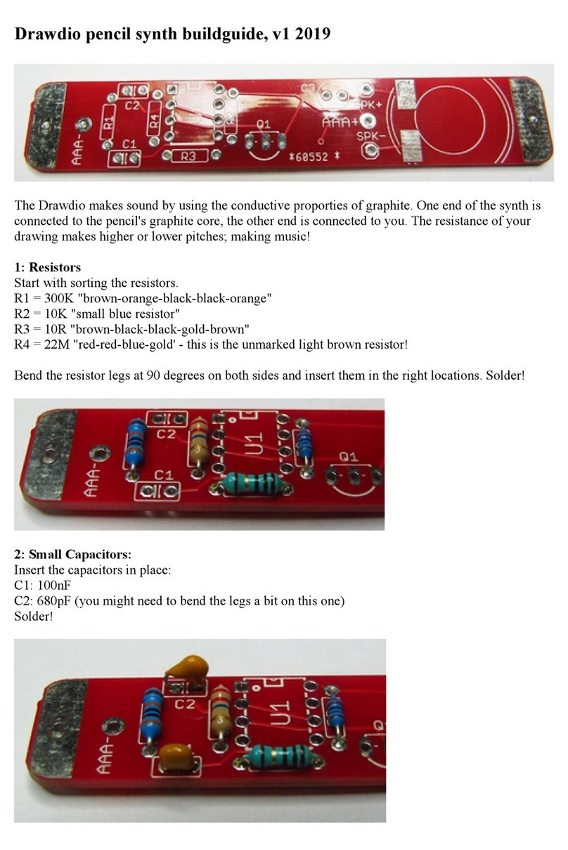
Q1 to Q4 are the 2n3904 transistors. They act as cv input buffers. Carefully bend the le s in the ri ht shape
solder them in.
Capacitors!
There are a lot of capacitors in the kit.
They determine the frequency ran e of the oscillators and stabilise the power and outputs.
We start with the three oran e disk-shaped capacitors.
C1, C2, C are 100nF (104)
The 100pF oes in C3. This is a sli htly smaller oran e disk with the code "101".
C5 = 1uF . This part is a blue blob with lon le s.
Now for the bigger capacitors:
These parts have a polarity. The lon le is the PLUS, The short le is MINUS.
The value of these components is printed on the side as well.
Start with the one lar er 7uF.
(take care to et the ri ht one, there are also four .7uF capacitors!)
Place the one 7uF capacitors in C7. Lon le oes into the PLUS!!
Now we do the four .7uF. These o in C6, C8, C9 and C10.
E pansion header:
For this expansion bay I've included a 16pin shrouded header.
There are 12 " reen" outputs that can be patched into the 3 "yellow" inputs.
The hole with the cross over it is a GND connection, so don't patch there!
This patch will define the sound of OUTPUT3. Use the female pin cable to make a connection.
I'm desi nin a expansion module that will allow for flexible automated switchin of these patchpoints.
This module will be connected to this expansion bay with a ribbon cable.
The Potentiometers:
These parts are variable resistors. With these you can adjust the frequency of the oscillators.
You have four of these.
P1 = B100K
P2 = B100K
P3 = B100K
P = B100K
Solder one le , check if the potmeters are strai ht in.Reheat to ali ned them correctly, then solder the rest.
