Revox PR99 User manual


sruDtrm neVox PR99 REPRODUCE ONIY
BEDIENUNGSANLEITUNG
OPERATI NG INSTRUCTIONS
MODE D'EMPIOI
SCHATTUNGSSAMMTUNG
SET OF SCHEMATICS
RECUEIT DE SCHEMAS
rqd/ex m6fiöx
tär * "',
n#cx
qü
t
I
E
*
&
I
@
@
@

STIJDtrR REVOX PR99 REPRODUCE ONLY
I NHALTSV ERZE I CHN I SCONTENTS REPERTO I RE
Blockdiagramm REV0X PR99 4 Block diagram REVOX PR99 4 Schdma bloc REVOX PR99 4
Al'lgemeines 5 General 5 Gdndral it6es 5 -
Bedienungselemente 6 0perating controls 6 0rganes de commande 6
I. BEDIENUNG 1/1 1. OPERATION 1/1 1. MODE D'EMPLOI 1/1
1.1 Band einlegen 1/1 1,1 Reel mounting 1/1 1.1 P.lacement de la bande 1/1
1.2 Laufwerk-Bedienungselemente 1/3 1.2 Tape drive controls 1/3 1,2 0rganes de commande du
mdcanisme 1/3
1.3 Wiedergabe-Bedienungs- 1.3 Reproduce control s 1/5 1.3 0rganes de commande de
elemente 1/5 lecture 1/5
2. E.O.M. INTERFACE UND INTERFACE- 2. E.O.[4. INTERFACE AND INTER- 2. E.O.M. INTERFACE ET PRISE D'
STECKER 2/1 FACE CONNECTOR 2/1 ]NTERFACE 2/1
2.1 Blockschaltbild 2/1 2.1 Block diagra^ ,,, 2.1 Schdma bloc 2/1
2,2 Interface-Stecker 2/2 2.2 Interface connector 2/2 2.2 Prise d'interface 2/2
3. TECHNISCHER ANHANG 3/1 3. TECHNICAL APPENDIX 3/1 3. SUPPLEI4ENT TECHNIQUE 3/1
3.1 Pflege und lnJartung 3/1 3.1 Care and maintenance 3/t 3.1 Soins et entretien 3/1
3.2 Einmessen 3/2 3.2 Cal ibration 3/? 3.2 Rdglages 3/2
3.2.1 Wiedergabekopfspalt- 3.2.1 Azimuth adjustment of 3.2.1 R6glage de l'azimut de la
Einstellung 3/2 reproduce head 3/2 t6te de lecture 3/2
3.2.2 Wiedergabe- und Ausgangs- 3.2.2 Adjustment of reproduce and 3.2.2 Rdglage de I'amplificateur --
Verstärker ab Testband ein- output level from test tape 3/3 de lecture et de sortie 3/3
stel I en 3/3
3.2.3 Ummessen auf anderen Leitungs- 3.2.3 Recalibration of the PR99 to 3.2.3 Rdglage d'un nouveau niveau
Pegel mit NF-Generator 3/4 another line level 3/q de sortie 3/4
3.2.4 Frequenzgangkontrol 1e 3/5 3.2.4 Checking of frequency 3.2.4 Contröle de la rdponse en
response 3/5 frequence 3/5
3.3 Einstellen der E.0.M. Regler 3/5 3.3 Adjusting the E.0.M. poten- 3.3 R6glage des potentiomötres
tiometers 3/5 de I 'interface E.0.M. 3/5
3.3.1 E.0.M. Stop Delay Time ein- 3.3.1 Adjusting the E.0.M. Stop 3.3.1 Rdglage du potentiomötre
stellen 3/6 Delay Time 3/A E.O.M. Stop Delay Time 3/6
4, SCHALTBILDER 4. SCHEMATICS 4, RECUEIL DES SCHEMAS
5. TECHNISCHE DATEN 5. TECHNICAL DATA 5. CARACTER]STIQUESTECHNIQUES
Prepared and edited by
STU DER- REVOX
Technical documentation
Al thardstrasse 1 0
CH-81 05 Regensdorf-Zuri ch
Swi tzerl and
We reserve the right to make alterations
Copyri ght by Wi 1 1 i Studer
Printed in Switzerland
Order number 18.656.1282

5TT[JDtrR Rd/OX PR99 REPRODUCE ONLY
BEDIENUNGSANLElTUNG PR99 OPERATING INSTRUCTIONS REVOX PR99 MODE D'EMPLOI REVOX PR99
I^jICHTIGE HINl,.lEISE
Schützen Sie Ihr Gerät vor übermässi-
ger Hitze und Feuchtigkeit. Stellen
Sie es so auf, dass die Lüftungsschlit-
ze nicht verdeckt werden.
Vor dem 0effnen des Gerätes unbedingt
den Netzstecker ausziehen. Das Gerät
darf nur an Wechselspannungsnetze an-
geschlossen werden (50. . .60H2).
Die Netzspannung kann Liber ein Span-
nungskarussell im Bereich 110/120/ 140U
und 20A/220/ 240V der örtlichen Strom-
versorgung angepasst werden.
IMPORTANT NOTES
Protect your tape recorder from ex-
cessive heat and humidity. Install it
in a manner which ensures the free
convection of a'ir through the ventil-
ati ng 1 ouvers.
There are no user serviceable parts
'inside the equipment, however, should
it become necessary to open the tape
recorder, it must first be disconnect-
ed from the electrical current supply.
Be sure to connect the unit to AC
(50...60H2) mains supplies on1y. For
operation on different supply volt-
ages, a voltage selector has to be
set to cover the nominal voltages of
110/120/ 140',1 or ?00/2?0/240V .
AVIS IMPORTANTS
Protdgez votre appareil d'un excös de
chaleur et d'humid'it6. Placez-le de
maniöre ä ne pas obstruer les fentes
d'adration. I1 est impdratif de re-
tirer la fiche secteur avant toute
intervention ä I'int6rieur de 1'appa-
reil. Ce dernier doit ötre aliment6
qu 'en cou rant al ternati f ( 50. .60H2 ) .
La tension peut Ctre adapt6e au rdseau
local -100/120/ 140vo1ts et 200/220/
240volts- par un carrousel de tension.
GARANTI E
Den Geräten, welche in Belgien, Bundes-
republ ik Deutschland und Frankreich
verkauft werden, 1 i egt ei ne spezi e1 1 e
Garantieanforderungskarte bei. Entweder
befindet sich die Karte in der Verpak-
kung oder in einer Plastiktasche an der
Verpackungsaussenseite. Sollte die Kar-
te fehlen, wenden Sie sich an Ihr REVOX
Fachgeschäft oder an thre REV0X-Landes-
vertretung.
Für in der Schweiz und 0esterreich ge-
kaufte Geräte gibt der Fachhändler die
Garantiebescheinigung ab. Bitte beach-
ten Sie, dass die Garantie nur im Ver-
kaufsland gü1t'ig ist. Ausserdem machen
wir Sie darauf aufmerksam, dass die
Garantie erlischt, wenn am Gerät unsach-
gemässe Eingriffe oder nicht fachmänni-
sche Reparaturen vorgenommen worden
sind.
l^IARRANTY
For equipment purchased in Belgium,
the Federa'l Republic of Germany and
France a special warranty card is
either contained in a plastic enve-
'lope attached to the outside of the
packi ng carton oli s encl osed with
the equipment. If this card is missing
please request it from your dealer.
Complete the warranty application card
and return it to your national distri-
buter who will then send you your
warranty card.
For equipment purchased in Switzer-
land and Austria, the warranty respon-
sibil ity rests with your dealer. Please
note that the warranty is not valid
outside the country of purchase.
The warranty will be voided if the
unit is tampered with or serviced by
unauthorized personnel .
GARANTI E
Tous les appareils vendus en France,
en Belgique et en RFA sont accompagn6s
d'un formulaire de demande de garantie
qui se trouve soit ä I'intdrieur de
I'emballage, soit dans une pochette en
plastique fixde ä I'extdrieur. Si ce
formulaire devait manquer, votre four-
nisseur REV0X ou 1'agent officiel
REVOX du pays d'achat vous 1e procurera
vol onti ers.
Pour les appareils vendus en Suisse et
en Autriche, la garantie est ddl ivr6e
par 1e distributeur officiel. Cette
garanti e n'est val abl e que dans 1 es
limites du pays d'achat. D'autre part,
nous vous rendons attentif au fait que
toute intervention non autoris6e ou
toute reparation non conforme nous l i-
böre automatiquement de toute obliga-
tion relative ä la garantie.
VERPACKUNG
Bewahren Sie die 0riginal-Verpackung
auf, Bei einem Transport ist diese
Spezialverpackung der beste Schutz für
Ihr wertvolles Gerät.
PACKING MATERIAL
Do not destroy the original packing.
If you ever have to transport your
equipment, this special packing will
provide the best possible protection
for your valuable tape recorder.
EMBALLAGE
Conservez soigneusement 1'emba1 lage
original. En cas de transport u1t6-
rieur, i1 constitue la meilleure pro-
tection pour votre appareil.

sTUDtrR REVOX PR99 REPRODUCE ONLY
BLOCK DIAGRAM REVOX PR99
REPRODUCE
HEAD
BEPFODUCE
H€AD
TFEBLE AOJ
I/2 REPRODUCE AMPLIFIER
DELAY TIME
LEVEL ADJ
+
+
LlNE
OUTPUT CHl
PHONES
OUTPUT CH1
nn
ALl
yI
PHONES
OUTPUT CA2
L NE
OUTPIJT CH?
=l
rr
BEPRODUCE AUDIO
AMPLIFIEB EOUALIZER SWITCH
LOW PASS MUTING
-t
OUTPUT
serecron I DRTvFR
L€VEL CH1 HEADPHONE
AMPLI FI E F
0,775V = 0VU
HEADPHONE
LEVEL CH2 AMPLIFIEF
L NE
$i,l'i',o
J
i
I
f-*-äl
+I
MUTING
SWITCH
-1I
I
MUTING
SWITCH
-I.*R'MAMPLFER
I '*,"' , on,
l*@
Ä
L- :J
I
L_
E.O.M.
INTERFACE
+ MOVE
STATUS

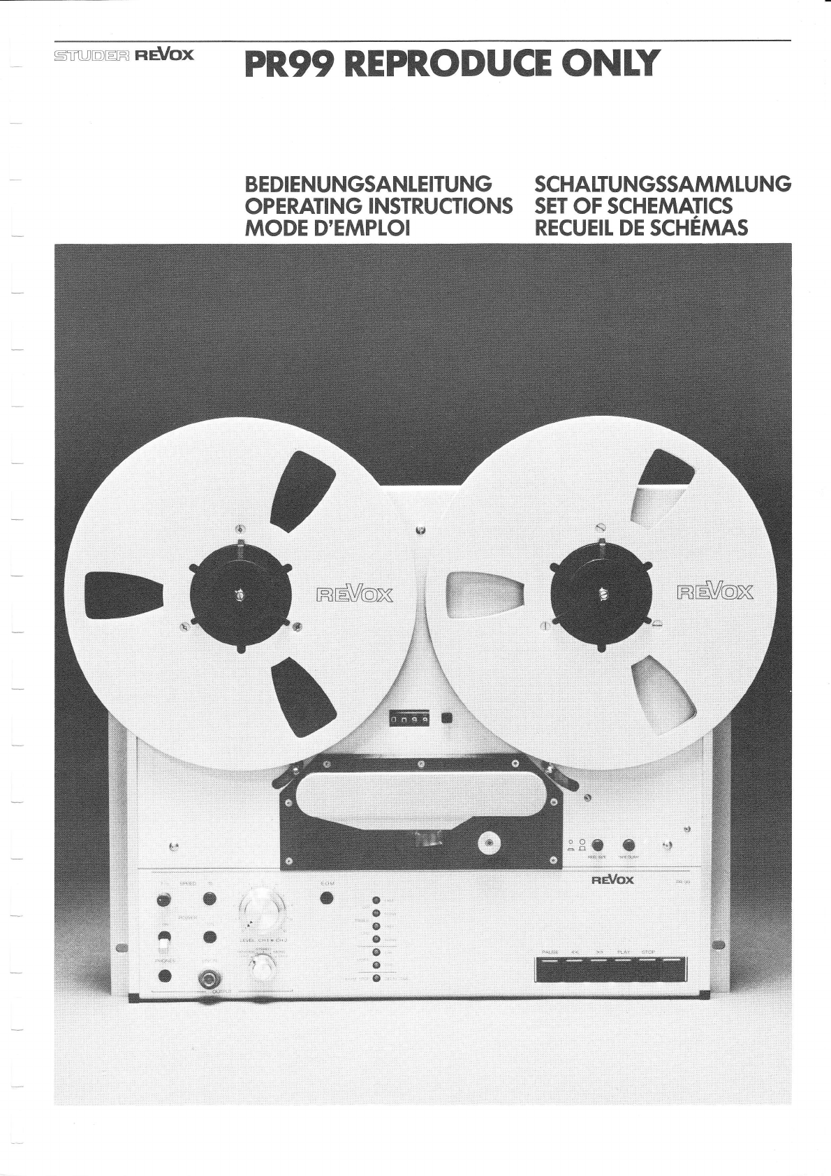
sTruDtrR neVox PR99 REPRODUCE ONLY
TONBANDMASCHINE REVOX PR99 REPRO ONLY
Die REVOX PR99 zeichnet sich durch
einfache Bedienung und viel seitige
Anwendungsmö91 ichkeiten im profes-
sionellen wie im Amateursektor aus.
Wartungsarbei ten oder Ei nmessvorgän-
ge sind ohne grossen Aufwand mög1ich,
da die entsprechenden Anschlüsse und
Regler von aussen zugängl ich s'ind.
Die PR99 ist fernsteuerbar und kann
über Fader gestartet werden.
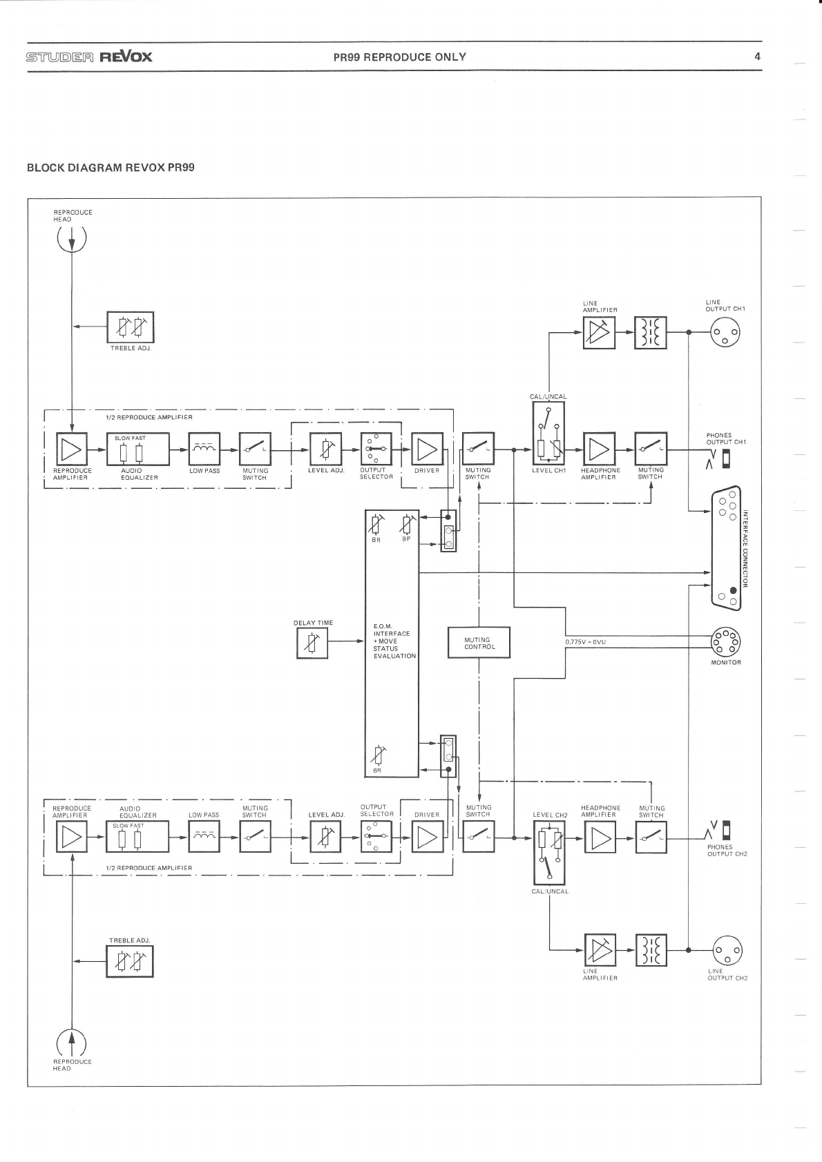
Die vorl iegende Version "REPRODUCE
0NLY" ist vor allem für die Rund-
funkautomatisation konzi piert wor-
den. Ein eingebautes End of message
(E.0.M.) Interface detektiert 25Hz
Impulspakete, die vom Anwender an
beliebiger Stelle auf dem Band auf-
gezeichnet worden sind und kann da-
rauf bel iebige externe Peripherie-
Geräte ansteuern mit einer einstell-
baren Verzögerungszeit von wenigen
ms bi s zu ca. 1 5s.
Kon zept
- 19" Normgehäuse oder l9" Einbaukorb
für Rackei nbau.
- Metallfrontplatte für Laufwerk und
Verstärkerteil.
- 3-Motoren-Di rektantrieb-Laufwerk.
- Der Bandzug kann den Spulenkern-
durchmessern entsprechend gewäh1 t
werden.
- Erhöhter Bandzug bei schnellem Um-
spulen, dadurch können freitragende
l,Jickel verwendet werden.
- Tonkopfträger auf der gleichen Ebene
wie das Bedienungsfeld, dadurch frei
zugäng l i ch.
- Edit- und Papierkorbbetrieb (Dump
Editing) wählbar.
- Fernsteueranschllisse für:
Faderstart (Bedienungsfeld verrie-
gel t)
Laufwerkfernsteuerung für alle Funk-
ti onen
Variable Bandgeschwindigkeitssteue-
rung (+7 Halbtöne).
- Symmetrische Ausgänge, können im Be-
darfsfal 1 auf Pegel regl er geschal tet
werden.
- Die Serviceregler sind von aussen
zugäng1 i ch .
- Der Kopfhörerausgang ist auch bei
kal ibriertem Ausgangspegel regelbar.
Fernsteuerungen sind als Zubehör er-
häl tl ich.
TAPE DECK REVOX PR99 REPRO ONLY
The REV0X PR99 series is an easy to
operate tape deck, designed for the
multiple needs of the broadcast stud.io
or demanding non professional use.
Maintenance and calibration are easy
to perform because the corresponding
connections and controls are accessi-
ble from the front. Fader start opera-
tion and remote controls are available
as options for the PR99.
The version "REPR0DUCE ONLY" was de-
signed especial1y for automatical
broadcast stations. A built-in end of
message interface (E.0.M.) detects
25Hz pulses that have been recorded
by the user at any required tape
position and controls any peripheral
equipment with an adiustable delay
of a few ms up to about 15s after
the 25Hz signal has stopped.
Design concept
- 19" standard
mounting. chassis case for rack
- Hardened aluminium front plate for
tape transport and ampl ifier.
- 3-motor direct drive tape transport
system.
- Tape tension switchable to match hub
d iameter.
- Increased tape tension during fast
wind allows use of single sided
spool s.
- Headblock assembly mounted on the
same plane as controls, hence more
eas i1y accessible.
- Edit and dump editinq accessible.
- Remote control connectors for:
Fader-start (front-panel controls
i nterl ocked )
All tape transport functions re-
motely control lable
Tape speed variable (+7 semitones).
- Balanced outputs switchab'le via
level control.
- Audio adjustments external)y acces-
s ibl e.
- Headphones volume adjustable even
with calibrated output 1eve1
The remote control units are
as options.
MAGNETOPHONE REVOX PR99 REPRO ONLY
Le REV0X PR99 se distingue par une
dtonnante facilitd d'emploi et par
un champ d'app1 ications aussi vaste
que vari6.
Les travaux d'entretien ou les op6ra-
tions de rdglage ne posent aucun pro-
b1Eme, car 1es prises et les instru-
ments correspondants sont accessibles
de l'extdrieur. Le PR99 peut ötre
command6 ä d.istance.
La version en question "REPRODUCE
0NLY" est sp6cialement constitu6e
pour 1'automatisation des 6missions
radio.
Un interface fin d'emission est in-
corpor6 pour 1a ddtection de blocs
d'impulsions de 25H2. I1s sont mis
par 1'uti lisateur sur divers en-
droits desirds de la bande.
Apräs chaque bloc d'impulsions
l'interface peut commander des
appareils externes avec un temps
de retard 169lable de quelques ms
jusqu'ä envi ron 15s,
Concepti on
- Boitier normalisd 19 pouces ou cor-
beille de montage 19 pouces pour
l'utilisation en rack,
- Plaque m6tallique frontale pour
m6cani sme et ampl i ,
- Entrainement direct par 3 moteurs.
- La tension de la bande peut 6tre
s6l6ct.ionnde en fonction du dia-
mötre du noyeau de la bobine.
- Tension de bande augmentde lors du
bobinage rapide, ce qui permet
d'utiIiser des bobines libres.
- Supports des t6tes magnetiques au
mOme niveau que le tableau de com-
mande pour en faciliter l'accös.
- Ddbit I ibre de la bande en lecture
( I ape Dump) .
- Prises de commande ä distance pour:
Fader Start (organes de commande
vdrouill6s),
'la commande de toutes Ies fonctions
m6can i ques
Ia commande de Ia variation de Ia
vitesse de d6filement de la bande
( J7 demi - tons ) .
- Suivant 1e besoin, les sorties
symdtriques peuvent ätre raccorddes
aux potentiomötres,
- Les potentiomötres de service sont
accessibles de I'extdrieur.
- La sortie casque est 6galement 16-
glable lorsque le niveau de sortie
est cal ibr6.
available Les commandes ä distance sont dispo-
nibles comme accessoi res.

Beigepacktes Zubehör:
Netzkabel, Bedienungsanleitung +
Schemasatz, Sicherungssatz (50OmAT,
B00mAT, 1AT, 1.6AT), je ein Stecker
für Kapstansteuerung, Tape Drive, Fa-
derstart, Monitor und Interface aus-
gang.
KONTROLLEN VOR DER INBETRIEBNAHME
- Ist das Spannungskarussell an der
Geräterlickseite auf die örtl iche
Netzspannung ei ngestel I t?
- D'ie Feinsicherung herausnehmen und
kontrollieren ob sie mit dem ange-
gebenen Wert (Technische Daten)
tibereinstimmt. Falls das Spannungs-
karussell umgestellt werden musste,
i st d i ese Kontrol 1 e unbedi ngt durch-
zuführen.
- t,lickelteller von Hand kurz drehen
um zu prijfen ob die Bremsbänder
nicht blockiert sind.
INBETRI EBNAHME
NF-(Tonfrequenz-) Leitungen anschl ies-
sen (Uebersichtsbild auf der Innen-
seite des ausklappbaren Blattes).
Alle Kippschalter müssen nach unten
gekippt werden. Die einrastenden
Schalter werden, fa11s gedrückt, durch
nochmal iges Drücken gelöst.
Das Gerät kann jetzt ans Netz ange-
schl ossen werden.
Standard accessories:
Power cord, operating instructionso
set of diagrams, set of fuses (500mAT,
BOOmAT, 1AT, 1.6AT), one connector
each for capstan control, tape drive,
fader start, monitor and interface.
PRE-OPERAT]ONAL CHECKS
- Does the setting of the voltage se-
lector at the rear panel match the
I ocal ma i ns vol tage?
- Remove fuse and check whetheri t
matches the technical spec ifications
This check is mandatory if the volt-
age selector needs to be adiusted.
- Briefly turn reel support to make
sure that the brake bands are not
bl ocked.
PUTTlNG INTO OPERATION
Establish AF (audio frequency) connec-
tions (general plan on the inside of
the fold-out page).
All toggle switches must be flipped
down, Any lock-down button which has
been depressed, will return to its
off position when'it is depressed
again.
The machine can now be connected to
the mains.
Accessoi res I i vrds avec I 'apparei I
Cäble secteur, mode d'emploi, jeu
de fusibles (500mAT, B00mAT, 1AT,
1.6AT), schdmas, 4 fiches pour:
Capstan speed, Tape Drive, Fader
Start, Monitor et Interface.
CONTROLES AVANT LA |\,IISE AU SERVICE
- La position du carrousel de ten-
sion situd au dos de 1'appareil,
correspond-elle ä la tension du
16seau 6l ectri que I ocal ?
- Sortez le fusible et contrölez
s'i1 correspond ä la valeur in-
diqu6e (caract6ri stiques tech-
niques). Si la position du car--
rousel de tension doit ötre mo-
difi6e, ce contröle est indis-
pensabl e.
- Faites tourner 1es plateaux ma-
nuellement pour vous assurer que
les bandes de freinage ne sont
pas b1 oqudes.
MISE EN SERVICE
Raccordez les sources BF (tableau
synoptique ä I 'intdrieur du ddpl i-
ant).
Tous les interrupteurs basculants
do i vent 6tre di ri gds vers l e bas.
Les interrupteurs ä maintien sont
I ibdr6s par une nouvelIe pression.
L'appareil peut maintenant Ctre rac-
cordd au secteur.

] sT[JDtrR Fld/OX PR99 REPRODUCE ONLY
LAUFWERK TAPE DECK MECANISME
WIEDERGABE REPRODUCE
ffiEre
ANSCHLÜSSE CONNECTORS RACCORDEMENTS

LAUFWERK
l1l linker hlickelteller
l2l rechter Wickelteller
t3l Bandzähler
t4l Bandzähler-Rückstel l taste
t5l I inker Banduml enkbol zen
t6l rechter Bandumlenkbolzen
17l Cutter-Sch i ebetaste
lBl Bandgeschwi ndi gkei tswah l tasten
t9l Netzschalter POI^JER+Kontrollampe
[10] Drucktaste flir Spulengrösse
REEL SIZE
l'l1l Drucktaste für Papierkorbbetrieb
[12] Pausentaste
[13] Rückspultaste
[14] Vorspultaste
l15l t,Jiedergabetaste
[16] Stopptaste
TAPE DECK
t1l Left-hand reel support
12) Right-hand reel support
t3l Tape counter
t4l Reset-button for tape counter
t5l Left-hand guide pin
t6l Right-hand guide pin
17J Cutter sl ide
t8l Tape speed selector buttons
i9l AC POWER switch+indicator lanrp
t10l REEL SIZE selector button
t11l TAPE DUMP button for dump editing
[12] Pause key
[13] Fast rewind key
[14] Fast forward key
[15] PLAY key
[16] ST0P key
MECANISME
l1l plateau de bobine gauche
l2l plateau de bobine droit
t3l compteur de bande
t4l touche de remise ä 0 du compteur
t5l guide de bande gauche
t6l guide de bande droit
l7l poussoir de montage
t8l touches de sdlection de vitesse
tgl interrupteur principal POt^lER+
l ampe tdmo i n
[10] touche pour diamötre de bobine
REEL SIZE
[11] touche pour 1e d6videment libre
de la bande
[12] touche de pause
[13] touche de rebobinage
[14] touche d'avance rapide
[15] touche de lecture
[16] touche stop
WEDERGABE
[ 1 7] Wi edergabepegel regl er
[ 1B] Kopfhöreranschl uss
[19] Wiedergabepegel -Umschal ter
[20] Ausgangswah l schal ter
t21l E.0.M. Kontrollampe
REPRODUCE
l17l Reproduce level control
[18] Headphone jack
[19] Playback level change-over button
[20] Mode selector
t21l E.0.M. indicator lamp
LECTURE
[ 1 7] rdgl age de n i veau en
[18] prise pour casque
[19] commutateur de niveau
[20] selecteur de sortie
[21] t6moin E.0.M.
I ectu re
de lecture
ANSCHLÜSSE
Tonmotors teu erung
Laufwerkfernbedi enung
Fern s ta rt
Moni tor-Ausgang
I n terface- Stec ke r
Lei tungsausgänge (symmetri sch )
CONNECTORS
Capstan speed remote control
Tape drive remote control
Fader start remote control
Monitor output
Interface connector
Symmetrical line outputs
RACCORDEMENTS
[1] variateur de vitesse
[2] commande ä distance du mdcanisme
l3l tdl6commande de d6part (Fader
Sta rt )
[4] sortie moniteur
[5] prise interface
[6] sorties 1 igne (symdtriques)
t1l
l?l
t3l
t4l
t5l
t6l
t1l
t2J
t3l
t4l
t5l
t6l


sTTJDtrR rlEVOX PR99 REPRODUCE ONLY sEcTtoN 1/1
1. BEDIENUNG
1.1
Band ei nl egen
Dreizackspule (DIN)
Vo11e Bandspule auf den linken l,^lickel-
telIer auf1egen. Die Dreizackführung
herausziehen und mit einer 60o Drehung
verriegeln (siehe Fig. 1.1).
NAB Spule
I'IAB-Adapter auf di e l^li ckel tel I er auf -
legen und Dreizackführung verriegeln.
NAB-Spu1e auf den Adapter auflegen
und das Adapteroberteil im Uhrzeiger-
sinn bis zum Einrasten verdrehen
(siehe Fig. 1.2).
1. OPERATION
1.1
Reel mounting
Three-pronged reel (DIN)
I'lount supply reel on left-hand reel
support and empty take-up reel on
right-hand reel support. Pull out
three-pronged guide and lock it with
a 60'rotation (see fig. 1.1).
NAB reel s
Mount NAB adaptor and reel support
and lock three-pronged guide.
Mount NAB reel on adaptor and turn top
section of adaptor clockwise until it
locks in place (see fig. 1.2).
1 . MODE D'EMPLOI
1.1
Placement de la bande
Bobine type cindma (DIN)
Placez la bobine pleine sur 1e plateau
gauche et la bobine vide sur'le p1a-
teau droit.
Soulevez la tige d'arr€t ä trois en-
coches et verrouillez-la en la fai-
sant pivoter de 60' (voir fig. 1.1).
Bobine NAB
Placez les adaptateurs sur les plateaux
et verroui I I ez I es ti ges d'arr€t ä
tro i s encoches. Posez ensui te l es bobi -
nes et tournez 1a partie sup6r'ieure des
adaptateurs, dans'le sens des aiguilles
d'une montre jusqu'au blocage (voir
fig. 1.2).
Plateau AEG (bobine ouverte)
Placez le disque adaptateur sur 1e p1a-
teau et verroui l l ez .la tige d'arr€t
ä trois encoches. Posez ensuite la
bobine pleine ä gauche (voir fig.1.3),
soulevez 1a languette et tournez ä
90" jusqu'ä ce qu'elle recouvre les
deux goujons de guidage. De.la möme
maniöre, placez ä droite un noyeau
de bobinage vide (voir fig. '1 .4).
Fig. 1.1 Fig. 1 .2
AEG-Bandtel I er (Offenwickel )
Adapterscheibe auf den l^Jickeltel ler
auflegen und Dreizackführung verrie-
geln (siehe F'i g. 1.3).
Auf der linken Seite den vollen Band-
wickel auflegen, die Lasche anheben
und um 90" verdrehen,bis sie auf den
beiden Führungsstiften aufl iegt. In
der g'l eichen l^iejse auf der rechten
Seite einen leeren l.^Jickelkern auf-
legen und verriegeln (siehe Fig. 1.4).
Fis. 1.3
AEG reel fl ange
Mount adaptor disk on the ree1 support
and lock three-pronged guide (see
f is. 1.3).
Itlount ful I reel on I ef t-hand reel
support; lift up cover plate and ro-
tate by 90' until it rests on the two
guide pins. After completing the pre-
ceding'instructions, mount an empty
core on the right-hand reel support
(see fig. 1.4).
Fis. 1.4

sIITJDtrR ]rEVOX PR99 REPRODUCE ONLY sEcTroN 1/2
Band einfädeln
Das Tonband nach untenstehender Ab-
bildung (Fig. 1.5) einfädeln. Das
Band muss sauber um die beiden Band-
umlenkbol zen l5l/t6l gelegt werden.
Der Bandanfang wird auf der rechten
Spule eingefädelt und durch einige Um-
drehungen im Gegenuhrzeigersinn ge-
sichert. Falls das Band mit einem
transparenten Vorspann beginnt, vor-
spulen, bis die Magnetschicht beginnt.
Den Zähler durch Drücken der Taste[4]
auf Null stellen.
Threading of tape
Thread tape according to the subsequent
illustrat'ion. The tape must be threaded
neatly around the two tape guide pins
l5l/t61. Thread leading tape end onto
right-hand reel and manual ly rotate
take-up reel in a counterclockwise
di recti on unt i I the tape i s I ocked.
Tape fitted with a .transparent leader
should be wound forward until the start
of the magnetic surface has passed the
heads. Set tape counter to zero by de-
pressing the reset key [4].
Enrou'lement de la bande
Enroulez la bande magn6tique selon
I'illustration suivante (fig. 1.5).
Avec pr6caution, faites passer 1a
bande autour des guides de bande [5]
et [6]. Enroulez l'amorce sur la bo-
bine de droite et assurez Ia prise
par quelques rotations dans le sens
contra i re des ai gui I I es d'une montre.
Si la bande est dotde d'une amorce
transparente, bobinez jusqu'ä ce que
apparaisse la couche magndtique. Re-
mettez 1e compteur ä zdro en pressant
I a touche [4].
Fig. 1.5

srt DtrR nd/ox PR99 REPRODUCE ONLY SECTION 1/3
1.2
Laufwerkbedi enungsel emente
CUTTER-SCHI EBETASTE [7]
Durch Betätigen dieses Schiebers wird
das Band an die Tonköpfe angelegt. Da-
durch ist es möglich, Schnittstellen
durch Drehen der Bandwickel von Hand
zu suchen. Diese Funktion kann mit der
Taste PLAY [15] oder durch leichtes
Drücken der Andruckrolle gegen die Ton-
we11e aufgehoben werden.
GISCHI^IINDIGKEITSWAHLTASTEN SPEED IB]
Die gewünschte Bandgeschwindigkeit
wird durch Drücken der entsprechenden
Taste ( ei nrastend ) angewähl t. Di e
Bandgeschwindigkeit kann in jedem be-
I iebigen Betriebszustand der Maschine
umgeschaltet werden.
NETZSCHALTER POI,IER [9]
Vor dem Einschalten sollte der Span-
nungswäh1er auf der Rückseite des Ge-
rätes kontrol I i ert werden I
Kippen des Schalters POWER [9] auf 0N
schaltet das Gerät ein. Im eingeschal-
teten Zustand leuchtet die Kontroll-
lampe rechts vom Netzschalter.
SPULENGROESSENSCHALTER REEL SIZE t1O]
Bei Verwendung von kleinen Bandspulen
(18cm oder kleiner) ist die Taste
REEL SIZE zu drücken. Bei einem Kern-
durchmesser von mehr als 60mm braucht
diese Taste nicht gedrückt zu werden.
DRUCKTASTE TAPE DUMP [1 1]
Wird diese Taste gedrückt, so ist der
rechte |^Jickelmotor ausser Betrieb. In
dieser Betriebsart können unbrauchba-
re Bandabschnitte durch Drücken der
Taste PLAY [15] "in den Papierkorb"
gespielt werden (daher auch der viel
verwendete Ausdruck Papierkorbbetrieb).
TASTE PAUSE [12]
Im Gegensatz zur Taste STOP [16] ist
es mit dieser Taste möglich, einge-
schal tete Betri ebszustände jederzei t
zu unterbrechen. Sobald die Taste
PAUSE t12l losgelassen wird,1äuft
das Gerät im eingegebenen Betriebs-
modus weiter. Für 1ängere Pausen kann
die einrastende Taste der Fernbedienung
verwendet werden.
1.2
Tape drive controls
CUTTER SLIDE i7]
When operating this s1 ide, the tape
will be pressed against the sound
heads. Thus, the cutting position
can be searched by manually turning
the reels. This function can be can-
celled by depressing the PLAY key t15l
or by slightly pushing the pressure
rol I er aga i nst the capstan,
SPEED SELECTORS SPEED TB]
Select desired tape speed by depressing
the corresponding button (self-locking)
The tape speed may be changed in any
operating mode.
I,{AINS SWITCH POWER 19]
Before switching on the tape deck,
check the setting of the voltage
selector at the rear of the tape deckl
The tape deck is switched on by set-
ting the POWER switch [9] to the 0N
position. When power is appl ied, the
indicator lamp right-hand from the
P0tlER switch wi 1 1 .l i ght up.
REEL SIZE BUTTONS [10]
When using small-diameter tape reels
(18cm or smaller), the REEL SIZE but-
ton [10] should be depressed. If the
hub diameter is larger than 60mm, this
button does not need to be depressed,
TAPE DUMP BUTTON [11]
The right-hand spool ing motor remains
disabled as long as this button is de-
pressed. In this mode, obsolete tape
sections can be played.into the "waste
paper basket" by depressing the PLAY
kev [15].
PAUSE KEY [12]
In contrast to the ST0P key [16], the
currently active operating modes can
be suspended at any time by depressing
the PAUSE key t121. As soon as the
key is released, the tape deck reenters
the previously establ ished operating
mode. For longer pauses, the self-
locking PAUSE key of the remote control
can be used.
1.2
0rganes de commande du mdcanisme
POUSSOIR CUTTER t7]
Permet de mettre la bande en contact
avec les tötes magndtiques. I1 sert
au repdrage acoustique des coupures
ä effectuer, en faisant tourner la
bande manuellement. Cette fonction
peut €tre annu'llde par 1a touche
PLAYI15] ou par une 169öre pression
du galet presseur sur I'axe de ca-
bestan.
TOUCHES DE VITESSE SPEED tB]
La s6lection de la vitesse de d6file-
ment de la bande se fait en pressant
la touche ä maintien correspondante.
Cette vitesse peut ötre modifi6e en
tout temps.
INTERRUPTEUR PRINCIPAL POI^IER T9]
Avant d'enclencher votre magndtophone
vdrifiez 1a position du carrousel de
tens ion, situ6 au dos de I 'appareil .
L'enclenchement se fait en plagant
f interrupteur POl^lER [9] sur 1a po-
sition 0N. Le tdmo.in ä droite de
I 'interrupteur s'al lume.
COMMUTATEUR REEL SIZE T1O]
S i vous uti I .i sez des bob i nes pl us pe-
tites que le diamötre standard ('lBcm
ou moins), pressez la touche REEL
SIZE t101. Cette opdration n'est pas
ndcessaire si le diamötre du noyeau
ddpasse 6Omm.
TAPE DUMP [11]
Cette touche d6clenche le moteur de
bobinage droite. En pressant ensuite
sur la touche PLAY 1151, cette fonction
permet le d6videment libre de la bande
dans une corbe i l l e ä papi er par exempl e,
pour 1 '61 iminatjon des segments inuti-
I i sabl es.
PAUSE [ 1 2]
Contrairement ä la touche STOP [']61,
el ) e permet d'i nterrompre en tout
temps une fonction sans la modifier.
Dös que la touche PAUSE t12l est re-
1ächde, la fonction in.i tia.l ement
choisie se poursuit. Pour des pauses
prolong6es i1 est possible d'util iser
la touche ä maintien de la commande ä
d i stance.

srrrotrR neVox PR99 REPRODUCE ONLY sEcTloN 1/4
TASTE t13l (Rückspulen) FAST REWIND KEY t13l T0UCHE ['13] (Rebobinage)
Diese Taste bewirkt sofortiges Rück- Depressing this key results in immedi- Cette touche commande 1e rebobinage
spulen des Bandes. Sie kann aus je- ate rewinding of the tape. This func- immddiat de la bande, en prioritd sur
der anderen Laufwerkfunktion gedrückt tion can be selectesd directly from les autres fonctions du m6canisme.
werden. Abgebrochen wird diese Funktion any other operating mode. The rewind Le rebobinage est interrompu soit par
entweder durch Drücken der Taste ST0P function terminates if the ST0P key[16] la touche ST0P [16], soit par le choix
[16], einer neuen Laufwerkfunktion is depressed, a new command is entered d'une nouveile fonction, soit par
oder am Bandende durch Ansprechen des or when the optical tape end sensor 'l'intervention du ddtecteur de fin de
optischen Bandendsensors. Befindet detects the end of the tape. bande. Lorsque 1e poussoir l7l est en
sich die Schiebetaste [7] in Cutter- llJith slider [7] in cutter position; the position cuttero la touche de rebobi-
Position, so reagiert diese Taste nur rewind function remains active only as nage [13] rdagit aussi longtemps
solange sie gedrijckt bleibt. Auf die- long as this key stays depressed, thus qu'elle est sollicitde, ce qui permet
se Art kann eine Schnittstelle moto- allowing motorized search of a cutting d'effectuer 1e repdrage des points de
risch gesucht werden. position. coupure sans intervention manuelle.
HINWEIS NOTE MISE EN GARDE:
Längere Bandabschnitte sollten nicht To reduce wear on the soundheads, long Afin de mdnager'les t6tes magndtiques,
in der Cutterposition umgespult wer- tape sections should not be wound in il est vivement recommandd de ne pas
den, da sonst die Tonköpfe zu stark ab- th cutter position, bobiner de longes segments de bande
genutzt werden. en position cutter.
TASTE t14l (Vorspulen) FAST F0RWARD KEY t14l T0UCHE ['14] (Avance rapide)
Diese Taste bewirkt sofortiges schnel- This key causes immediate fast forward Cette touche commande le ddfilement
1es Umspulen des Bandes. Die Anwen- winding of the tape. It is used in the rapide et immddiat de la bande. Ses
dungsmöglichkeiten sind die gleichen same manner as key [13]. possibilitds d'utilisation sont iden-
wie bej Taste ['13]. tiques ä celles de la touche de re-
bobinage 1131.
TASTE PLAY t15] PLAY KEY T15] TOUCHE PLAY T15]
Die Wiedergabefunktion wird durch diese The reproduce function is initiated by Cette touche commande la fonction de
Taste ausgelöst. Sie darf auch während depressing the PLAY key. It may also lecture. E11e peut 6tre sollicitde si-
dem schnellen Umspulen eingegeben wer- be depressed whi'le fast forward or re- multandment avec le bobinage et
den. wind is active. l,avance rapide de la bande
TASTE STOP [16] STOP KEY [16] TOUCHE STOP [16]
Diese Taste löscht den eingegebenen This key cancels the current mode of Cette touche permet d'interrompre
Betriebsmodus. Das Gerät bleibt be- operation. The tape deck is ready to et d'annuler toute fonction.
triebsbereit, accept a new command. L'appareil reste cependant pr6t ä
fonct i onner.

STUDtrR lrd/Ox PR99 REPRODUCE ONLY sEcTloN 1/5*
l.l i edergabebedi enungseI emente
PEGELREGLER LEVEL [17]
Die Funktion des Reglers ist abhängig
von der Stellung des Schalters UNCAL
[19]. Ist d.ieser Schalter gelöst, so
beeinf'lusst der Regler nur den Kopf-
hörerausgang [18], ist er gedrlickt,
beeinflusst er den Kopfhörerausgang
und den Leitungsausgang.
BeT der Stereoausführung ist der Reg-
'ler mit einem Doppelpotentiometer be-
stückt. Der innere Regei ist dem Ka-
nal 'l (links), der äussere Regler dem
Kanal 2 (rechts) zugeordnet.
Die Regler sind über eine Rutschkupp-
lung miteinander verbunden und kön-
nen für Balanceeinstellungen gegen-
einander verdreht werden.
KOPFHOERERAUSGANG PHONES I1B]
6.3mm Klinkenbuchse für einen Kopf-
hörer (Impedanz mind. 200 Ohm). Der
Kopfhörerausgangspegel ist mit dem
Regler LEVEL [l7l einste] lbar.
SCHALTER UNCAL T19]
In ge1östem Zustand ist der kalibrier-
te Ausgangspegel direkt auf die Aus-
gänge geschaltet. Bei gedrijcktem
Schalter UNCAL t19l wird der Ausgangs-
pegel ijber den Regler LEVEL t17l be-
einflussbar.
BETRI EBSARTENSCHALTER [ 2O]
Ueber den Betriebsartenschalter l20l
kann die Wiedergabebetriebsart ange-
wählt werden (schaltet Kopfhörer-
und Leitungsausgänge) :
STERE0 beide Kanäle werden getrennt
wi edergegeben
M0N0 beide Kanäle werden gemischt
wiedergegeben (prüfen der
Monokompati bi 1 i tät )
REVERSE wie STERE0, jedoch mit ver-
tauschten Kanälen
CH1/CHz nur der angewäh1te Kanal wird
auf beiden Ausgängen wieder-
gegeben
E.0.M. K0NTROLLAMPE [21]
leuchtet auf sobald das E.0.M. Inter-
face ein 25Hz Pulspaket auf dem Band
detektiert hat.
1.3
Reproduce control s
LEVEL C0NTR0L t17l
The function of this control is de-
pendent on the setting of switchl19].
When this button is in the released
position, this control only affects
the Ievel of the headphone. If but-
ton l21l is locked in place, LEVEL
control [17] regulates the headphone
as well as the line outputs.
tn-sf6ieo models, this control is
implemented by a dual-operated poten-
tiometer. The inner control is assign-
ed to channel 1 (left), the outer con-
trol to channel 2 (right).
The controls are interconnected with
a slip friction clutch and thus can
be individually adjusted for balancing.
HEADPHONE JACK T1B]
Jack socket for one set of headphones
(impedance min. 200 ohms). The output
level of the headphone iack can be ad-
justed with LEVEL control [17].
UNCAL St^JTTCH [19]
When this button is released, the cali-
brated fine output level is connected
directly to the outputs. if the UNCAL
button il91 is locked in place, the
output level can be adiusted with
LEVEL control t171.
MoDE SELECToR [20]
The reproduce mode is determined by
the setting of the mode seiector
(switches phones and l ine outputs):
STERE0 individual reproduction on
both channels
MONO
REVERSE
reproduction is intermixed
on both channels (check mo-
no compati bi I i ty )
same as STERE0, however,
channel s are reversed
CHl/CHz The channel selected will be
reproduced on both channels
E.0.M. INDICAToR LAMP [21]
fights up as soon as the E.0.M. inter-
face has detected a 25Hz signal on
the tape.
1.3
0rganes de commande de lecture
REGLAGE DE NIVEAU LEVEL t17]
Les fonctions de 169lage de niveau de-
pendent directement de 1a position
du commutateur [19]. Si ce commutateur
n'est pas sol l icit6, le rdglage n'agit
que sur la sortie du casque. Dans le
cas contraire, 1e rdglage agit ä la
fois sur la sortie du casque et sur la
!6Ffie I isne.
Dans l'exdcution st6r6o, 1e 169lage
est en fait un double potent'iomötre,
I'un ä f intdrieur, pour 1e canal I
(gauche), l'autre ä l'extdrieur, pour
le canal 2.
Accoupl6s, les potentiomötres peuvent
mutuel lement servir au rdglage de 1a
ba I ance .
soRTrE CASQUE PHoNES t18l
Pnise jack pour un casque d'dcoute
(impddance au moins 200 ohms). Le
niveau de sortie du casque se rögle
ä I'a.ide du potentiomötre LEVEL ['17].
COMMUTATEUR UNCAL TI9]
Non soll icit6, le niveau de ligne ca-
librd ag'it directement sur'les sorties.
Lorsque le commutateur UNCAL [19] est
enfoncd, le niveau des sorties peut
ötre influencd par l' intermddiaire
du rdgulateur LEVEL [17].
SELECTEUR DE MODE [20]
Le s6lecteur de mode permet de choisir
1e genre de lecture (commande les sor-
ties de ligne et de casque):
STEREO lecture sdparee des deux ca-
na ux
M0N0 lecture mixte des deux ca-
naux (contrö1e de compatibi-
I i td mono)
REVERSE lecture stdrdo avec canaux
'inversds
CHI/CHZ lecture sur les deux sorties
du seul cana'l choisi.
TEMotN E.0.M. t21l
S'al lume lorsque un bloc d'impulsions
de 25Hz a 6t6 ddtect6 par 'l'interface
E.0. M.


sTTUDtrR REVOX PR99 REPRODUCE ONLY SECTION 2/1
2. 2. 2.
E.O.M. INTERFACE UND INTERFACE-STECKER E.M.O. INTERFACE AND INTERFACE CONNEC- E.O.M. INTERFACE ET PR]SE D'INTERFACE
TOR
2.1 2.1 2.1
E.0.M. Interface-Blockschaltbild Block diagram E.0.M. interface Schdma bloc de l'interface E.0.M.
I
eo.ü. NrE-iFAcE Boano Fr.-
--{_
T
Y. LOW
Y. PLAY
Y - STSTL (TAPE MODE)
AMPLI F I ER
TO INTERFACE
CONNECTOR
*i
Fig.2.1
CUE TONE
l25Hzl
B-EOM
K2
DELAY CI RCUIT
K1 ms... approx. 15s
approx. 80ms
Fig.2.2

S]TIJDtrR rrEVOX PR99 REPRODUCE ONLY sEcTtoN 2/2*
2.2
I nterface -Stec ker 2.2
Interface connector 2.2
Prise d'interface
I13
aoooooooooooo
oooaoooooooa
25
't4
PINOUT INTERFACE CONNECTOR
1 ALLPASS OUTPUT CHANNEL 1 (UNBALANCED)
2 ALLPASS OUTPUT CHANNEL 2 (UNBALANCED)
3 AUDIO GROUND
4 S-STOP-2
5 S-STOP-1
6 S-E0M-2
7 S-EoM-1
B Y-PLAY (OPEN COLLECTOR)
9 Y-STSTL (OPEN COLLECTOR)
1O LINE OUTPUT CHl (BALANCED) OUT-1B
11 LINE OUTPUT CH1 (BALANCED) OUT-1A
12 +24,0Y
13 S-ST0P
14 LINE OUTPUT CHz (BALANCED) OUT-28
15 LINE OUTPUT CHz (BALANCED) OUT-2A
16 SCREEN
17 S-STOP-O
1B B-EoM (oPEN COLLECTOR)
19 S-E0M-0
2O Y-LOWSPD (OPEN COLLECTOR)
21 LOGIC GND
22
23
24 S-PLAY-D
25
I max. for all open collector outputs = 100m4
For further information see
section 4 (E.0.M. PCB)
Fi 9. 2.3


sru@trR neVox PR99 REPRODUCE ONLY SECTION 3/1
3. TECHNISCHER ANHANG
3.I
Pflege und Wartung der REVOX PR99
Die Wartung der REVOX PR99 beschränkt
s i ch auf das Rei n i gen und Entmagneti -
sieren der Bandführungselemente.
H i nwei s:
Bei der Reinigung der Kapstanachse
darf keine Reinigungsflüssigkeit in
die Lager gelangen.
Für die Pflegearbeiten verwendet man
am besten das REVOX Reinigungsset
(Best.-Nr. 39000). Es enthält alle
zur Reinigung notwendigen Utensilien
und eine spezielle Reinigungsflüssig-
keit. Das Schmieren der Sinter- und
Kugel l ageli st aus der Servi ce-Anl e i-
tung zu entnehmen,
Vorgehen:
Ein Filzstäbchen mit der Reinigungs-
f l üss i gkei t benetzen und al I e Band-
führungselemente damit reinigen. Da-
nach m'it einem neuen,trockenen Filz-
stäbchen die gereinigten Stellen trock-
Entmagneti sieren:
Ungefähr al I e 1 00 Betri ebsstunden
sollten die Tonköpfe und Bandfüh-
rungen entmagnetisiert werden. Dazu
wi rd eine Entmagnetisierungsdrossel
(Best.-Nr. 10.042.002.01 ) verwendet.
3. TECHNICAL APPENDIX
3.1
Care and maintenance of the
3. SUPPLEMENT TECHNiQUE
a,
J.I
REVOX PR99 Soins et entretien du PR99
The maintenance work is reduced to
cleaning and demagnetizing the tape
guidance elements.
Note:
During the cleaning, take care that
no cleaner comes into the bearing of
the capstan axle.
For optimum cleaning use the REV0X
cleaning set (0rder No. 39000).
It contains al I utens il s necessary
for cleaning the machine and a special
cleaning fluid. Lubrication of the
sintered bearing bushes and of the
ball bearing is described in the ser-
vice instructions.
Procedure:
Dip a felt swap into the cleaning
fluid and clean al l tape guidance
elements. Dry the cleaned surface
wjth a new, dry felt swap.
Demagnetizing:
After approx. every 100 hours of ope-
ration demagnetize the sound heads
and tape guidance elements. Use a
demagnetizer (Order No. 10.042.002.01).
L'entretien du REV0X PR99 se limite
au nettoyage et ä la d6magn6tisation
des organes de guidage de la bande.
Attenti on:
Lors du nettoyage de I'axe de cabestan
veillez ä ce qu'aucun produit liquide
ne pdnötre dans les paliers.
Pour I es travaux d'entreti en uti I i sez
de prdf6rence le set de nettoyage
REV0X (No de com. 39000). Il contient
tous les utensiles ndcessaires ainsi
qu'un 1 iquide sp6cial . Pour le
graissage des roulements, r6fdrez-
vous aux instructions de service.
Proc6dez comme suit:
Munissez-vous d'un bätonnet de feutre;
trempez-1e dans le 1 iquide spdciai et
nettoyez tous les organes de guidage
de la bande. Sdchez ensuite ä I'aide
d'un bätonnet de feutre neuf et sec.
Ddmagndti sati on:
Nous recommendons de ddmagn6tiser 1es
tCtes magn6tiques et 1es guides de
bande toutes les 100 heures de service.
Pour ce fai re, uti i i sez un ddmagndti -
seur (No. de com. 10.042.002.01 ).
Reinigung an Kopfträger und Bandführungen
Cleaning of head block and tape guides
Nettoyage du bloc de tAtes et des guides de bande
Losch kopl
Erase head Wiedergabekopf
Feproduci ng head
Täte de lecture
Tonwelle
Capstan shaft
Axe de cabestan
Tete d'eff actement
Linke Umlenkrolle
Left-hand tape guide
gurde de band qauche
Bandausgleichshebel Rechter Umlenkbolzen
Right hand tape guide
Guide de band droit
And ruckro lle
Pinch roller
Galet presseur
Bandführu ng
Tape gu ide
Guide de bande
Tape tension arm
Tendeur de bande
I nf rarot Lichtschranke
lnfrared light-barrler
Barriäre lu mineuse inf rarouge
Ban dabhebebo I zen
Tape lift pins
Goulon de retrait de bande
Fi g. 3. '1
Other manuals for PR99
1
Table of contents
Other Revox Tape Deck manuals