Filterbausatz BLII Nachrüstung/ englisch DORW2133 14. 1.2 1 3/4
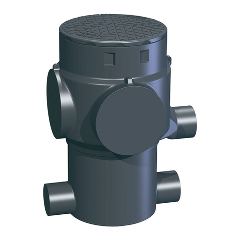
Overview
A Inflow pipe section DN1
B Inflow bend DN1 67°
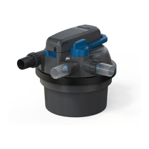
C Filter body
D Moulding in-/overflow DN1
E Gasket
F Inflow pipe in the tank DN1 (on side)
G Calmed Inlet
H Safety screw for inflow clamed inlet
(on side)
I Connection service pipe
Notes:
•Existing pipelines in the tank need to be attached on the side
with double sleeves DN1 with B and D (D may need to be
shortened). Then the position of the filter will be in the middle of the tank opening.
•The pre-mounted gaskets in a new tank, delivered from factory, may, under certain
circumstances, need to be dismantled and reinserted again, according to the
directions given.
Mounting:
1. The inflow pipes A and B are inserted.
2. 1.2. The inflow pipe in the tank F is cut to the correct length (i.e. lower edge opening
B vertically to the bottom of the tank) and joined to the calmed inlet with safety
screw H. Then attach to the down pointing opening of the filter body C.
3. Place moulding D with the gasket E to the filter connection and then pass through the
gasket.
4. Connect filter body C with the inflow pipe F and the calmed inlet G in the tank, then
insert in the sleeve of B and afterwards into the filter connection from D (gasket E).
5. Once the inflow pipe is vertically straight in the tank and the calmed inlet is on the
bottom of the tank, the assembly is finished. If not, the length of the inflow pipe
needs to be adjusted. (points 2, 4, 5).
Rewatec GmbH January 2 1
Technical changes and rights reserved. No liability for misprints.
The contents of the technical documentation are a component of the guarantee terms
