Rewatec Maxi User manual
Vorfilter Maxi/Prefilter Maxi DORW3106 08.03.2014 1/10
Einbau- und Montageanleitung
Vorfilter Maxi
Seite 2 –5
Assembly instructions and mounting guide
Prefilter Maxi
Page 6 –10

Vorfilter Maxi/Prefilter Maxi DORW3106 08.03.2014 2/10
Technische Dokumentation
1. Einsatzbereich
Der Filter Maxi wird für die mechanische Reinigung des
Regenwasserzulaufs für Regenwasseranlagen,
Versickerungsanlagen und Teiche eingesetzt.
Die Durchlassweite der Maschen beträgt 0,9 mm, so dass
eine feine Filterung erfolgt.
Die maximal anschließbare Fläche (Dach, Terrasse) beträgt
ca. 350 m². Der Filter enthält in der Grundausstattung einen
Deckel, der für den Einbau in Verkehrsflächen der Klasse A
(Radfahrer, Fußgänger) geeignet ist. Der Einbau bei höheren
Verkehrslasten (PKW, LKW) ist ebenfalls möglich.
Inhalt Seite
1.
Einsatzbereich
3
2.
Funktionsweise, Anschlussvarianten/Vormontage
4
3.
Betrieb/Wartung
4
4.
Hauptabmessungen
5
5.
Einbau, allgemeine Hinweise
6
5.1
Einbau begehbare Version
6
5.2
Einbau befahrbare Version PKW
7
5.3
Einbau befahrbare Version LKW
8
Hinweis:
Die Befolgung und Berücksichtigung der in dieser technischen Dokumentation und
der Dokumentationen der mit diesem Produkt in Verbindung stehender
Komponenten enthaltenen Angaben sind Bestandteil der Garantiebedingungen.
Vorfilter Maxi/Prefilter Maxi DORW3106 08.03.2014 3/10
Lamellendichtung
DN100
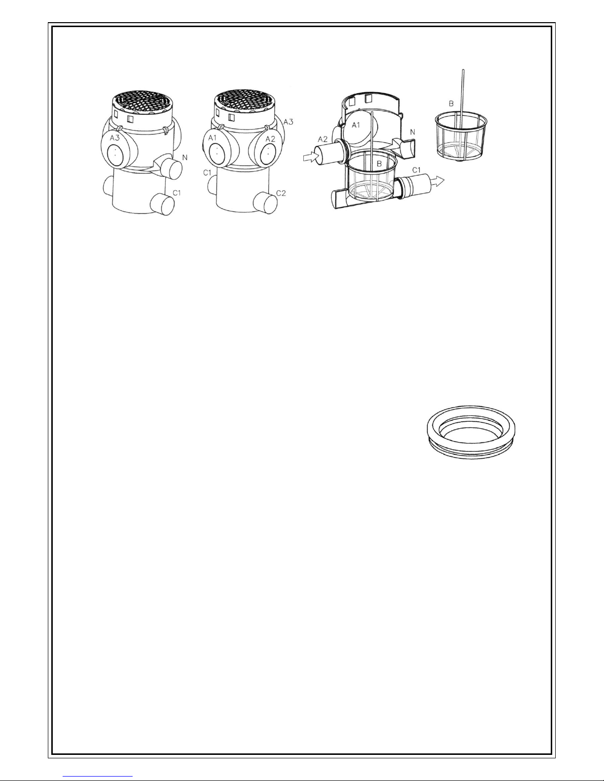
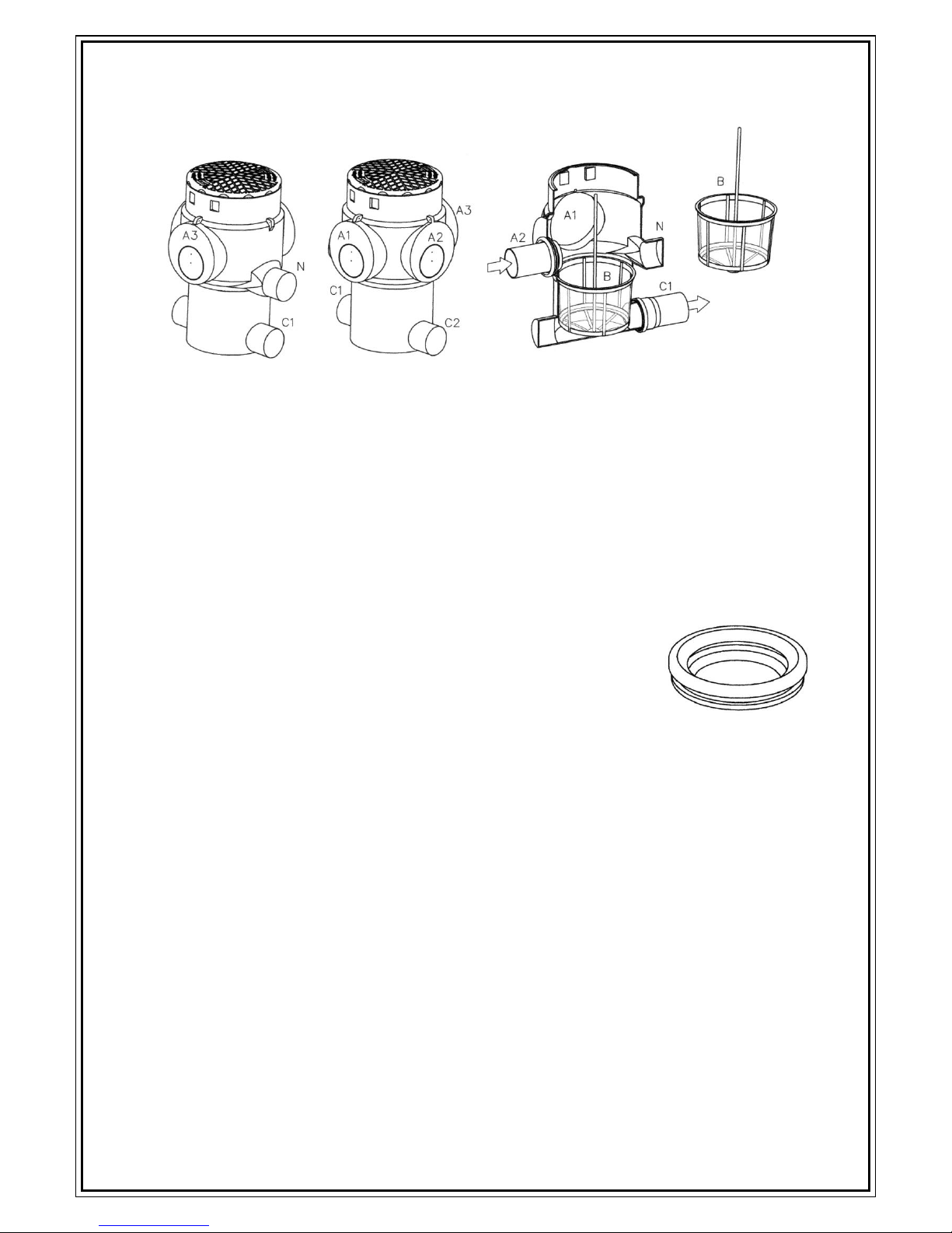
2. Funktionsweise, Anschlussvarianten/Vormontage
Funktionsweise
Das zu filternde Regenwasser fließt durch einen oder mehrere Zuläufe (A,A2,A3) in den
Filterkorb (B), dessen Maschen mit einer Durchlassweite von 0,9 mm durch Zurückhalten
mechanische Verschmutzungen entfernen. Das gefilterte Regenwasser verlässt den Filter
durch einen oder beide Abläufe (C1 und/oder C2).
Anschlussvarianten/Vormontage
Der Zulauf oder die Zuläufe kann/können aus drei verschiedenen
Richtungen angeschlossen werden, siehe Anschlussflächen A1, A2
und A3. Die Anschlussflächen enthalten kreisförmige Nuten als
Sägemarkierung, passend zur mitgelieferten Lamellendichtung
DN100. Die gewünschte Anschlussfläche ist an der Markierung
auszusägen, zu entgraten und dann die Dichtung einzusetzen. Bei
mehreren Zuläufen sind zusätzliche Lamellendichtungen
erforderlich, siehe Zubehör.
Für die gewünschte Ablaufrichtung gibt es zwei gegenüberliegende
Stutzen (C1 und C2). Um einen Stutzen als Ablaufleitung nutzen
zu können, muss er etwa 10 mm vor dem Ende abgesägt werden;
es kann dann eine Muffe DN 100 aufgeschoben werden.
Der Stutzen „N“ kann als Notüberlauf genutzt werden.
3. Betrieb/Wartung
Um eine störungsfreie Funktion zu gewährleisten muss der Filterkorb regelmäßig entleert
und gegebenenfalls gereinigt werden. Die Reinigungsintervalle sind für jede Installation
durch regelmäßige Kontrolle individuell festzulegen.
A1, A2, A3
Anschlussmöglichkeiten Zulauf oder Zuläufe
B
Filterkorb mit Entnahmestange
C1, C2
Anschlussmöglichkeiten Ablauf oder Abläufe
N
Anschlussmöglichkeit Notüberlauf

Vorfilter Maxi/Prefilter Maxi DORW3106 08.03.2014 4/10
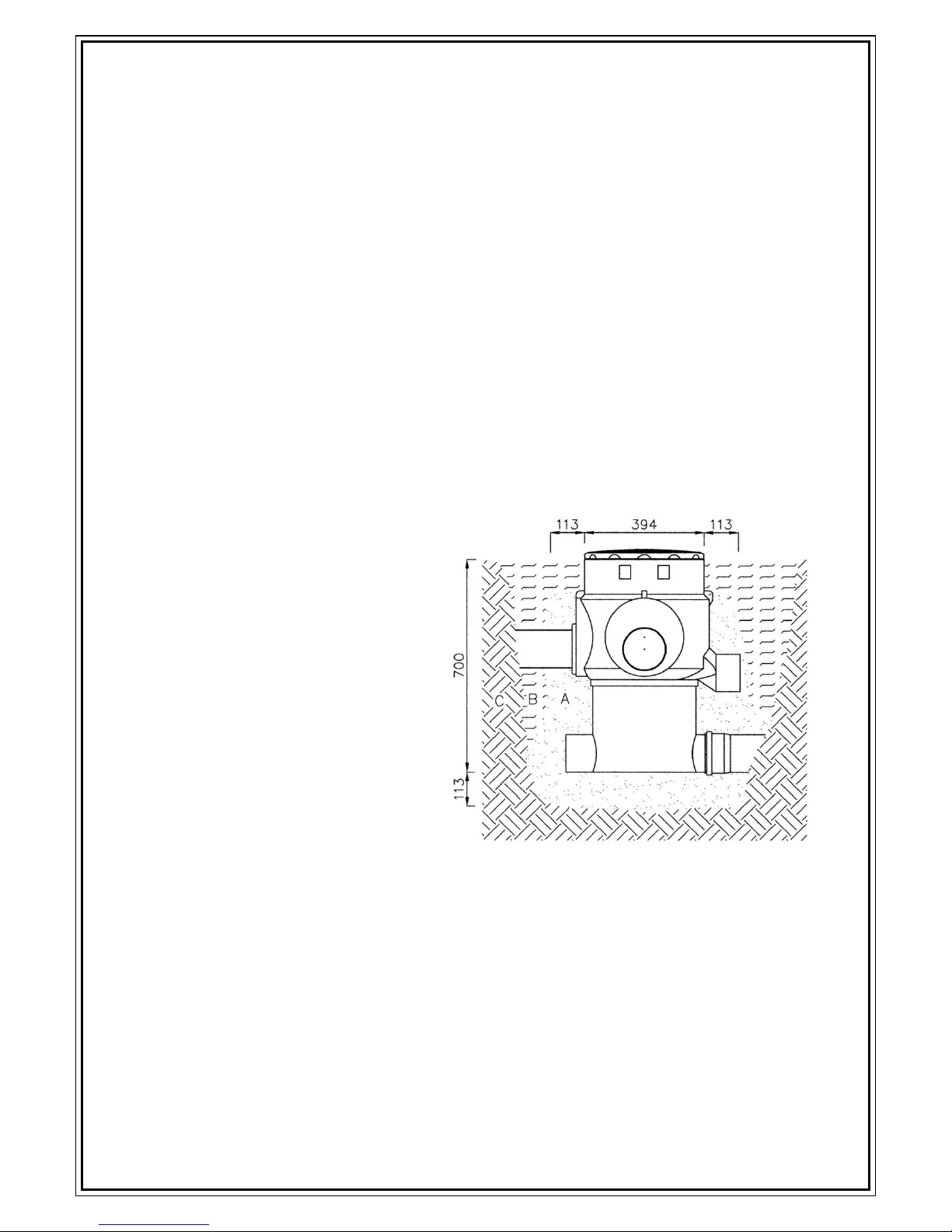
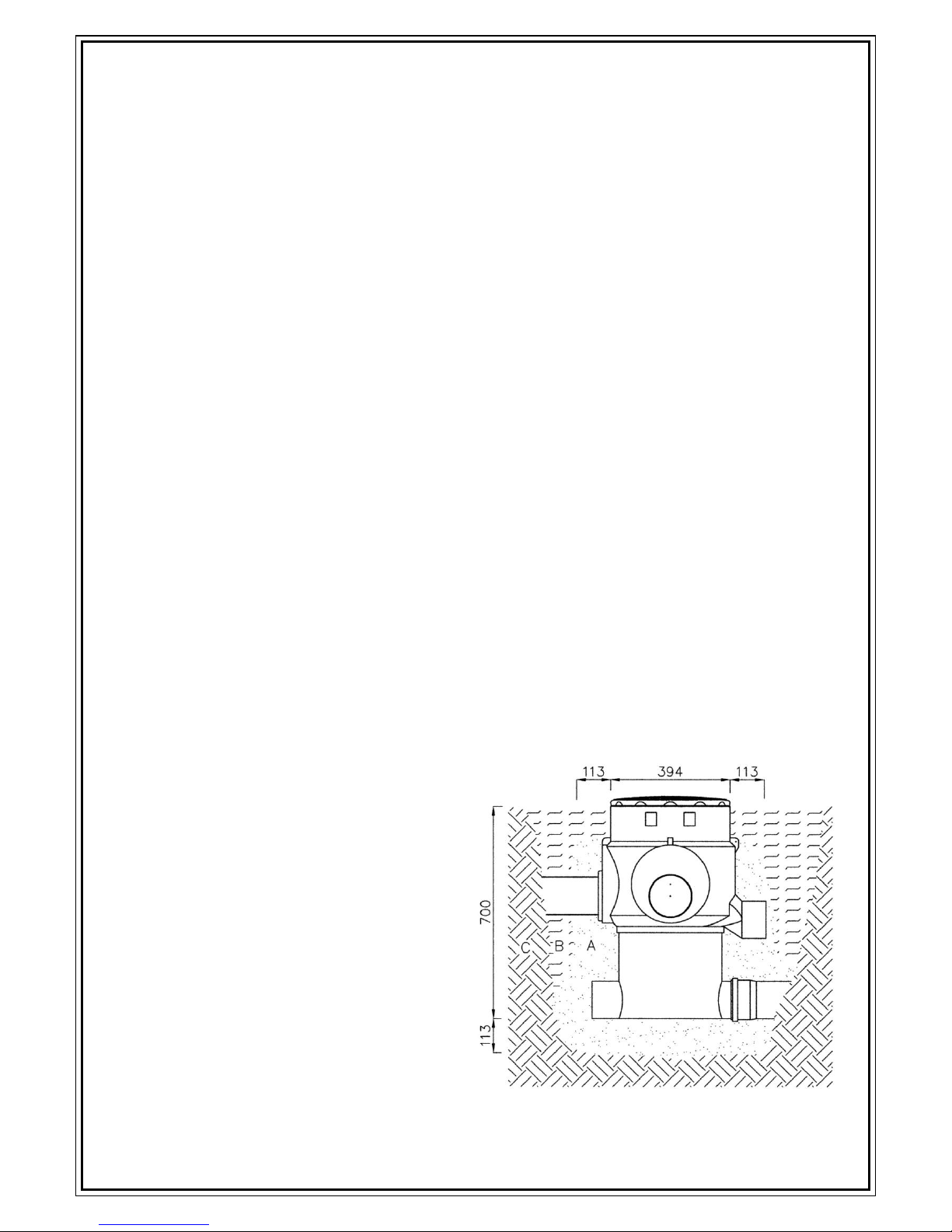
4. Hauptabmessungen
Die Rohrverlängerung ist in einem
Bereich von 70mm durch schieben
stufenlos höhenverstellbar und
darüber hinaus durch absägen kürzbar
oder durch stapeln verlängerbar, so
dass sich beliebige Einbautiefen bis
maximal zulässig 1,5 m. realisieren
lassen.
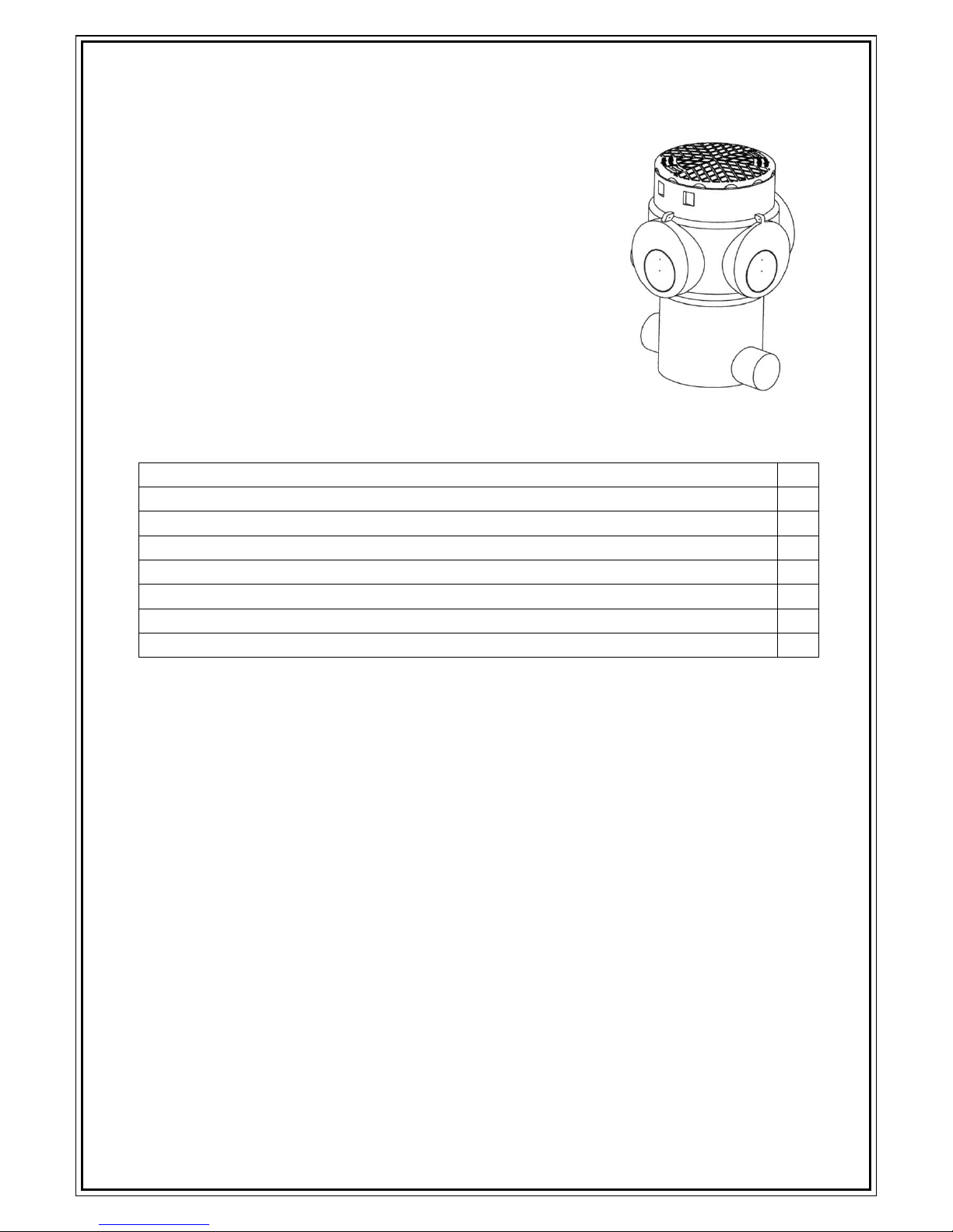
Filtergehäuse
Filtergehäuse mit Rohrverlängerung
Vorfilter Maxi/Prefilter Maxi DORW3106 08.03.2014 5/10
5. Einbau
Allgemeine Hinweise
Baugrube: Bei der Standortwahl und der Gestaltung ist zu vermeiden, dass
Beschädigungen an vorhandenen Leitungen, der Vegetation oder Gebäuden entstehen.
Verfüllmaterial: Das Verfüllmaterial sollte tragfähig, gut verdichtbar, frostsicher sein, am
besten ein weitgestuftes Sand-/ Kiesgemisch (z.B. Körnung 0/32). Nicht verwendbar sind
bindige Böden wie Mutterboden oder stark lehmhaltige Böden wie Hangschutt. Aushub kann
verwendet werden, wenn er den oben genannten Kriterien entspricht.
Anschlussleitungen: es ist unbedingt darauf zu achten, dass die Ablaufleitung ein gleich
großes oder stärkeres Gefällen vom Filter aufweist als das Gefälle der Zulaufleitung zum
Filter. Bei Nicht-Beachtung läuft der Filter bei starken Regenereignissen über. Dasselbe wie
für die Ablaufleitungen gilt auch für eine eventuelle Notüberlaufleitung.
5.1 Einbau begehbare Version
Ablauf des Einbaus
1. Aushub der Baugrube
2. Herstellen einer etwa 100 mm dicken Bettung aus Verfüllmaterial, gut verdichten
(Maschine, oder drei Arbeitsgänge mit Handstampfer 15 Kg / Kantholz o.ä.)
3. Einsetzen und ausrichten des Filters, Rohrverbindungen anschließen.
4. Verfüllen mit Verfüllmaterial in
etwa 100mm dicken Lagen. Die Dicke
des Verfüllmaterials um das
Filtergehäuse sollte ca. 100 mm
betragen. Der Rest der Lage kann mit
Aushub verfüllt werden. Die Lagen
sind einzeln zu verdichten, z.B. mit
15 Kg Handstampfer / Kantholz o.ä.
ohne Maschineneinsatz.
Diese Art der Verfüllung sollte bis
etwa 100 mm unter Gelände-
oberkante durchgeführt werden.
5. Die restliche Verfüllung ist beliebig
Einbau PKW befahrbar:
Belastungsklasse B (PKW, Kleinbus, max. Achslast 2,2 To): PKW Komplett Set (Anleitung
DORW2126; Punkt 3 Bilder 10, 13 und 16). Mindestabstand Tankoberseite zur
Erdoberfläche: 600 mm.
Einbau LKW befahrbar:
SLW30 Belastungsklassen D (LKW max. Achslast 11,5 To): Zwischenring nötig, weitere
Information in Anleitung DORW2127 sowie Punkt 3 Bilder 10, 13 und 16. Mindestabstand
800 mm zwischen Schulterhöhe Tank und Oberkante Fahrbahnbelag.
REWATEC GmbH März 2014
Technische Änderungen und Rechte vorbehalten. Keine Haftung für Druckfehler
Die Inhalte der technischen Dokumentation sind Bestandteil der Garantiebedingungen
Es sind bei Planung und Einbau die einschlägigen Normen und andere Regelwerke sowie die Unfallverhütungsvorschriften zu
beachten.
A Verfüllmaterial gemäß Punkt 5.
B Verfüllung mit Aushub o.ä.
C anstehender Boden
Vorfilter Maxi/Prefilter Maxi DORW3106 08.03.2014 6/10
Technical documentation
1. Application area
The filter Maxi is used for the mechanical cleaning of the
rainwater inflow for rainwater plants, seepage plants and
ponds.
The width of the mesh (0.9 mms), assures a very fine
filtering
The maximum connectable surface (roof, terrace) is
approximately 350 m². The basic filter contains a cover which
is suitable for the installation in public thoroughfares of the
class A (cyclist, pedestrian). The installation in areas with
higher traffic loads (passenger car, truck) is also possible.
Contents Side
1.
Application Area
6
2.
Operating mode, connection possibilities/pre-mounting
7
3.
Operation/servicing
7
4.
Main dimensions
8
5.
Installation, general notes
9
5.1
Installation walkable version
9
5.2
Installation version drivable for cars
10
5.3
Installation version drivable for lorries
10
Important notice:
The contents of this technical documentation and corresponding manuals are a
component of the guarantee terms
Vorfilter Maxi/Prefilter Maxi DORW3106 08.03.2014 7/10
Lamella gasket
DN100
2. Operating mode, connection possibilities/pre-mounting
Operating mode
The rainwater to be filtered flows through one or several inflows (A, A2, A3) into the filter
basket (B) with a mesh width of 0.9 mms to remove debris. The filtered rainwater leaves
the filter by one or both outflows (C1 and/or C2).
Connection possibilities/pre-mounting
The inflow or the inflows can be connected from three different
directions, see connection surfaces A1, A2 and A3. The connection
surfaces contain circular grooves as a saw mark, into which the
supplied lamella gasket DN100 fits. The chosen connection point
needs to be sawn of and smoothed as marked on the filter, then
the gasket is fitted. With several inflows additional lamella gaskets
are necessary, see accessories.
For the desired outflow direction there are two opposite openings
(C1 and C2). To be able to use an opening as an outflow pipe it
must be sawn off about 10 mms before the end; then a sleeve DN
100 can be put on it.
The opening "N" can be used as an auxiliary overflow.
3. Operation/Servicing
To guarantee quality filtering the filter basket must be emptied regularly and be cleaned as
necessary. The frequency of cleaning is determined by checking the filter regularly.
A1, A2, A3
Connection possibilities inflow or inflows
B
Filter basket with withdrawal rod
C1, C2
Connection possibilities outflow or outflows
N
Connection possibilities overflow

Vorfilter Maxi/Prefilter Maxi DORW3106 08.03.2014 8/10
4. Main dimensions
The pipe extension is height-
adjustable by pushing up 70 mms at
a time or to shorten it can be sawn
off to size. The maximum installation
depth allowed 1.5 m.
Filter body
Filter body with pipe extension
Vorfilter Maxi/Prefilter Maxi DORW3106 08.03.2014 9/10
5. Installation
General notes
Excavation pit: Existing pipelines, pipes, vegetation as well as other specifics have to be
considered, so that damages and hazards will be avoided.
Filling material: The filling material has to be load bearing, well compactable and frost
free. The best would be sand/gravel e.g. grain size 0/32.
Excavation soil can only be used if it fulfils the above criteria. Topsoil, loam or clay are not
suitable for the backfilling.
For the drivable versions (points 5.2 and 5.3) limestone graining 2/45 or equivalent
material is to be used for the rubble base layer.
Connection pipes: it is very important that the outflow pipe shows an equally strong or
stronger slope from the filter than the slope from the inflow pipe to the filter. With
nonobservance the filter overflows with heavy rainfall. This also applies to the outflow pipe.
5.1 Installation walkable version
Workflow of the installation
1. Excavation of the pit
2. Fill with about 100 mm thick bedding of filling material, compact it well (machine, or
three operations with hand tamper 15 kg / squared timber or similar)
3. Insert and adjust the filter, joining the pipe connections.
4. Fill in with filling material in about 100 mms thick layers. The thickness of the filling
material around the filter body should be about 100 mms. The rest of the layer can be filled
with excavated soil. Every layer has to be compacted, e.g. with a hand tamper 15 kg /
squared timber or similar, without machine usage.
This filling should continue to about 100 mms under the top edge of the ground.
5. The rest filling can be chosen arbitrarily
A Filling material according to point 5.
B Filling with excavated soil or similar
C surrounding ground

Vorfilter Maxi/Prefilter Maxi DORW3106 08.03.2014 10/10
Installation - drivable for cars:
Load class B (passenger car, minibus, max. axle load 2.2 To): Passenger car Complete set
(instructions DORW2126; point 3 pictures 10, 13 and 16). Minimum distance from top of
filter to the earth's surface: 600 mm.
Installation - drivable for lorries:
SLW30 load classes D (truck max. axle load 11.5 To): Spacer ring necessary, further
information in instructions DORW2127 as well as point 3 Pictures 10, 13 and 16. There must
be a minimum distance of 800 mm between the top of the filter and road surface.
REWATEC GmbH März 2014
Technical changes and rights reserved. No liability for misprints
The contents of the technical documentation are a component of the guarantee terms
Planning and installation regulations are to be followed, as well as the accident prevention regulations.
Table of contents
Languages:
Other Rewatec Water Filtration System manuals


Popular Water Filtration System manuals by other brands

Aquasana
Aquasana OptimH2O EQ-OPTM installation instructions

T.I.P.
T.I.P. HNB 1600 E operating instructions

Parker
Parker F55 Series Installation & service instructions

Schenker
Schenker SMART 30 Installation, use and maintenance manual

Davey
Davey EAFM7 Installation and operating instructions

Aries
Aries HIGH PURITY WATER SYSTEM Operation & maintenance manual


