Page 2 SB-6-148-F
INSTALLATION
Certain solvents, paints and chemi-
cals may attack plastic bowl and
can cause bowl failure. Do not use
near these materials.
Do not place unit in service without
metal bowl guard installed. Plastic
bowl units are sold only with metal
bowl guards. To minimize the dan-
ger of flying fragments in the event
of plastic bowl failure, guard must
not be removed. If the unit is in
service without the metal bowl
guard installed, manufacturer's
warranties are void and the manu-
facturer assumes no responsibility
for any resulting loss. If unit has
been in service and does not have a
metal bowl guard, order one and
install before placing back in ser-
vice.
1. Be sure to read all "Warnings", "Cau-
tions" and "Notes" in this manual
and on unit before installing or using
this equipment.
2. Install filter as close as possible to
point where air is being used. Install
main air shut-off valve and standard
pipe union (supplied by user) up-
stream of filter to allow maintenance
to unit.
3. Install unit with air flow through filter
in direction of arrow on top of unit.
4. Minimum 3/4" piping is recom-
mended. Avoid using fittings, cou-
plings, etc. that restrict air flow.
5. The filter includes a 3/4" elbow which
allows vertical pipe installation.
Mount filter in a vertical position.
SAFETY PRECAUTIONS
This manual contains important information that ALL users should know and understand BEFORE using the equipment. This
information relates to USER SAFETY and PREVENTING EQUIPMENT PROBLEMS. To help you recognize this information, we use
the following terms to draw your attention to certain equipment labels and portions of this manual. Pay special attention to any label
or information that is highlighted by one of these terms:
Important information - a hazard that
may cause serious injury or loss of
life.
Important information that tells how
to prevent damage to equipment, or
how to avoid a situation that may
cause minor injury.
Note
Information that you should pay spe-
cial attention to.
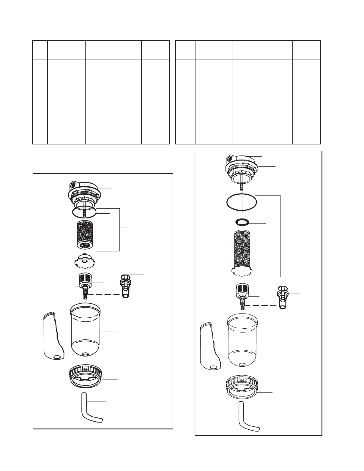
DESCRIPTION
The CleanAir air control units are de-
signed to remove dirt, pipe scale, and
most liquid aerosol. The HAF-503 150 CFM
separator filter includes a 5 micron filter
element. The HAF-508 150 CFM coalesc-
ing filter includes a .01 micron filter ele-
ment. Both filters include an automatic
drain which expels liquids which accumu-
late in the filter bowl.
SPECIFICATIONS
Filter Port Sizes 3/4" NPT(F)
MaximumInletPressure 150 PSIG (10.3 Bar)
MaximumTemperature 150°F (65.6°C)
Risk of personal injury.
Risk of property damage.
Except as otherwise specified by
the manufacturer, this product is
specifically designed for com-
pressed air service and use with
any other fluid (liquid or gas) is a
misapplication. For example, use
with or injection of certain hazard-
ous gases in the system (such as
ozygen or liquid petroleum gas)
could be harmful to the unit or
result in a combustible condition
that may cause fire or explosion.
Manufacturer’s warranties are void
in the event of misapplication and
manufacturer assumes no respon-
sibility for any resulting loss.
6. Do not install filter in an application
where the pressure drop will exceed
20 psi. For example, a quick opening
valve located upstream from the fil-
ter could cause a momentary pres-
sure drop in excess of 20 psi.
7. Maximum inlet pressure and operat-
ing temperature is 150 PSIG (10.3
bar) and 150°F (65.6°C).
8. A 6 ft. length of vinyl tubing is
shipped loose with the unit. Slide
over automatic drain which protrudes
from bottom of bowl. Place other end
of vinyl tubing into appropriate
receptable (i.e. below booth grating,
can, etc.). Prevent vinyl tubing from
becoming kinked which would pre-
vent free movement of liquids dis-
charged from the automatic drain.
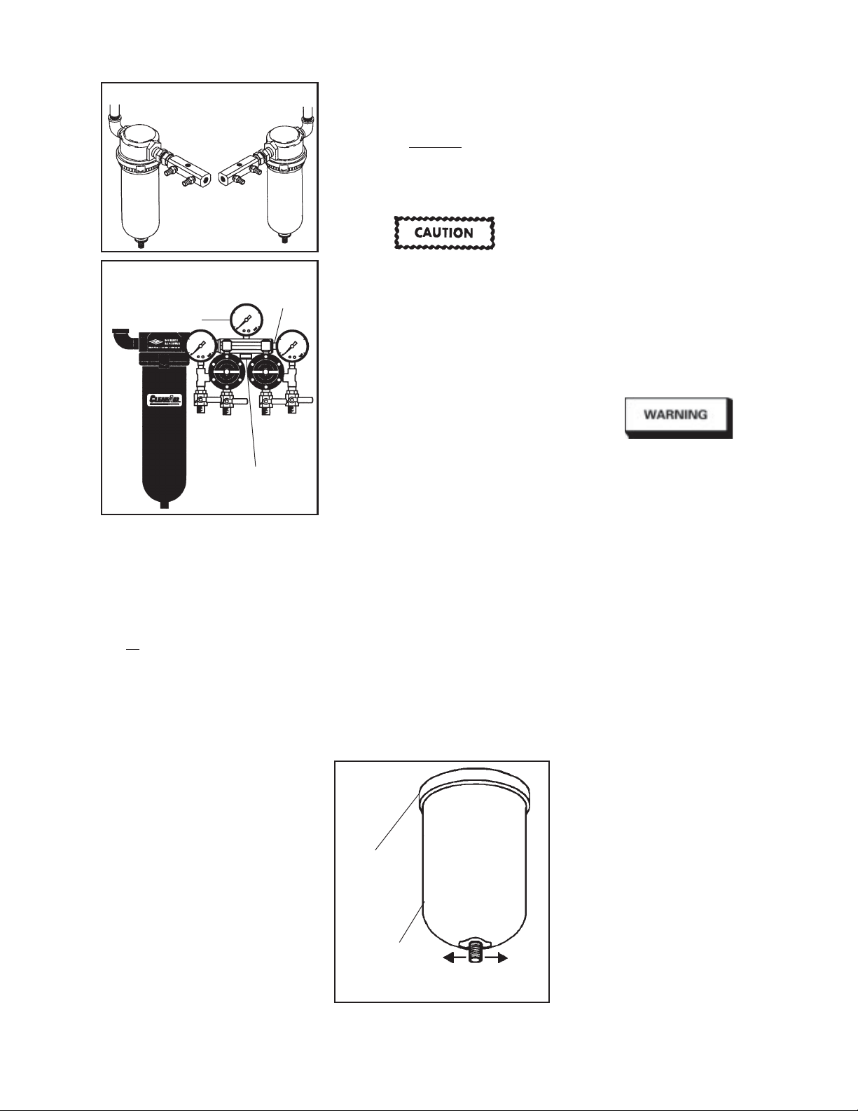
9. An optional manual drain (HAF-11) is
supplied loose in the carton (see Item
10 or 11, Fig. 4 or 5). If desired, this
can be installed in place of the auto-
matic drain.
Model HFRL-511 or HFRL-513
Instructions:
In addition to Steps 1-9 above;
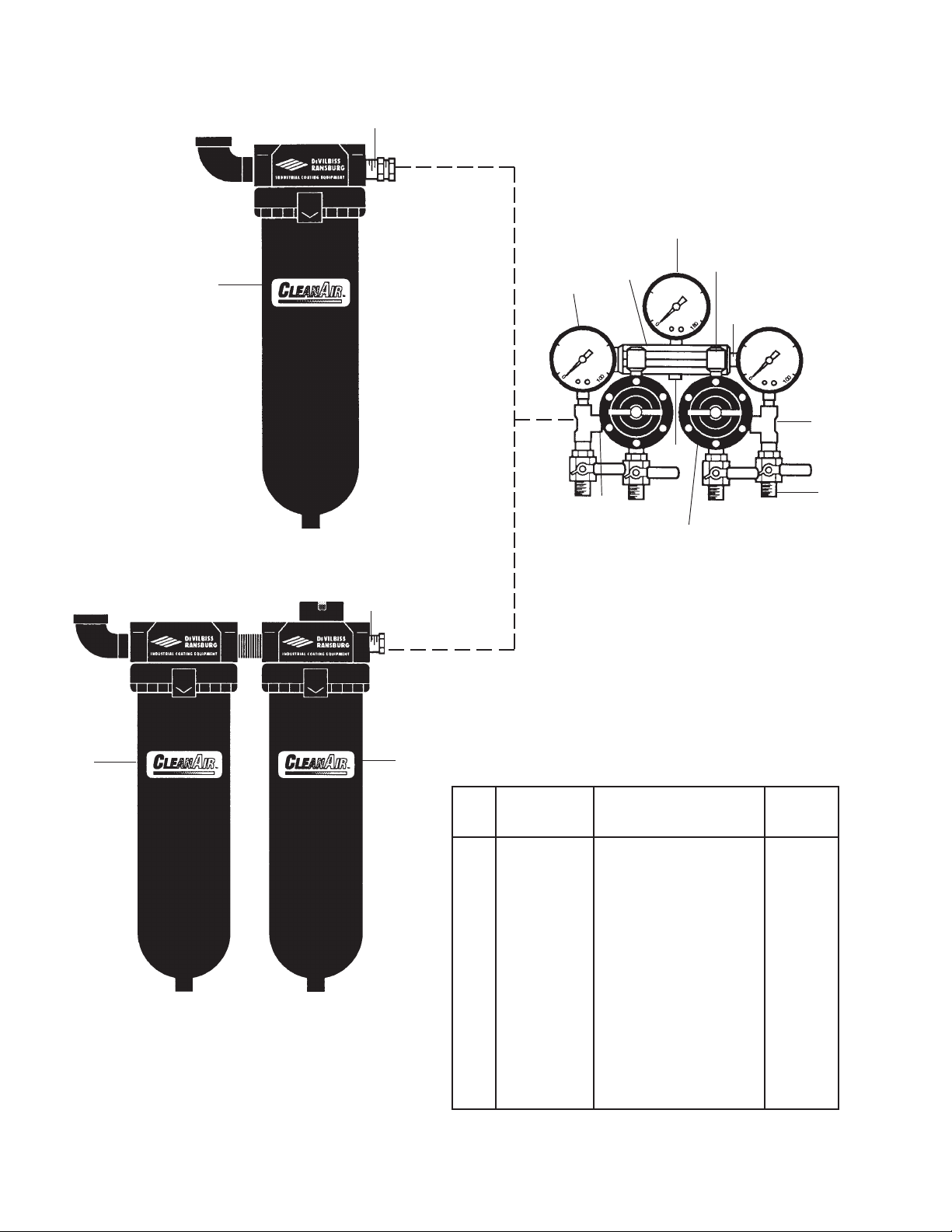
10. Install manifold into swivel connec-
tion on outlet of filter. Note pipe seal-
ant is not required. Orient manifold
for right or left hand operation (See
Fig. 1). Tighten swivel connection.
11. Install 0-160 psi air gauge into 1/4"
NPT(F) port in top of manifold using
pipe sealant (See Fig. 2).