RF SOLUTIONS MAINSLINK User manual

Features:
• Quick and Simple to Install
• No Configuration Needed
• Up to 500m range outdoor
• 50-100m range in buildings
• Weatherproof IP65 Enclosures
• Easy Screw Terminal Connection
• Operates from 230V or 110V
• UK Design and manufacture
Part Number Description
MAINSLINK MAINSLINK System (Supplied complete with Tx/Rx)
MAINSLINK-RX MAINSLINK Receiver unit
Description
MAINSLINK is a plug and play solution to replace a switched live cable.
When 230Vac “LIVE” is input to the transmitter, the receiver provides a
230Vac “LIVE” switched output at its screw terminals.
Ordering Information
230Vac Radio Link
MAINSLINK System Operation
NEUTRAL IN
LIVE IN is
OFF
LIVE IN
SWITCHED
OUT OFF
NEUTRAL IN
MAINSLINK-TX MAINSLINK-RX
NEUTRAL IN
LIVE IN is
230Vac
LIVE IN
SWITCHED
OUT 230Vac LIVE
NEUTRAL IN
MAINSLINK-TX MAINSLINK-RX

Cable Connections
MAINSLINK is very easy to connect, simply wire as follows:
MAINSLINK-TX - Transmitter:
1. Run a switched Live from your external device or switch to the
MAINSLINK-TX Transmitter and connect into the screw terminal
marked: L (Live)
2. Run a Neutral to the MAINSLINK-TX and connect to the terminal
marked N (Neutral).
LIVE IN
NEUTRAL IN
CABLE IN
EARTH
MAINSLINK-RX - Receiver:
1. Connect the Supply: LIVE IN & NEUTRAL.
2. Connect the LOAD: L1 Output and Neutral
This device is Double Insulated i.e. does not require a
safety connection to earth. However earth terminals are
provided for convenience to ensure earth continuity if
required
SWITCHED LIVE
OUT
L2 (N/C)
N (NEUTRAL)
L1 (N/O)
N (NEUTRAL)
EARTH
L (LIVE IN)
CABLE IN
S U P P L Y L O A D
EARTH
EARTH
Warnings :
• Product is not independently isolated, ISOLATE the mains electricity supply before
removing the cover and observe any relevant safety precautions. Maintenance to the
product that involves removal of the cover should only be carried out by a competent
person or qualified electrician.
• F2 Fuse rating is 4A (T) 250 H (Ceramic). Replace fuse with same type and rating.
• Relay is rated at 10A peak, and 5A constant.
• Product must be connected to a switch fused (spur/supply) or BS 1363 Plug.

36.00
88.00
88.00~25.00
30.00
Fixing Instructions:
1. Fix the rear of the MAINSLINK enclosure to the wall using the template above.
2. Ensure that all fixing screws are screwed flush to the enclosure.
3. Ensure that the screw covers are put in place. These ensure water proofing and
insulate the PCB from the wall fixing screws. Screw Covers are found inside the
rear of the enclosure.
4. Screw the on front plate with the PCB in place. Check that its not upside down!
Wall Mounting
Template
All dimensions in mm
Dimensions and Wall Mounting

Pairing a Receiver
NOTE: MAINSLINK Systems are supplied pre-paired. This process is de-
scribed for advanced use only.
Erasing a Receiver
2. When the receiver is in learn
mode you will need to pair the
transmitter within 10 seconds. To
do this,
3. Apply a 230Vac supply to the
transmitter for 2 seconds and
then turn it off.
4. Allow 15 seconds for the receiver
to return to normal operation.
230Vac
To erase all transmitters from the
MAINSLINK-RX hold a magnet beside the
learn switch for 10 seconds as shown
NOTE: You cannot erase individual
MAINSLINK-TX units.
To pair the MAINSLINK–RX it must have a
230Vac supply connected.
1. Briefly place a magnet on the receiver by the
MAINSLINK-RX as shown
This will put the system in learn mode.

Operational Features and Advanced Instructions
System Communication:
The MAINSLINK-TX transmitter sends aa Radio message to the MAINSLINK-RX Receiver every time
the MAINSLINK-TX power is applied or removed. The MAINSLINK-RX receiver then mirrors the MAIN-
SLINK-TX Transmitters’ status on its output.
Failsafe “Watchdog” feature
When enabled, the MAINSLINK-TX automatically sends a background signal every 20 secs when it is
active.
MAINSLINK-RX expects to receive this background watchdog signal. If it fails to receive one watchdog
signal within a two minute period it will deactivate its output. If the Watchdog signal is lost an LED
will flash to show signal has been lost.
Momentary / Latching Jumper
When used as a Mainslink system the Jumper link 3-4 must be OPEN (Momentary operation).
When the Mainslink Receive r is sued with an alternative Transmitter such as a pocket keyfob then
the Link can be set to Latching operation if so required
Multiple system operation:
Each MAINSLINK transmitter is uniquely coded, this means that no two systems will cross operate
by default. If multiple transmitters or receivers are required to work together the MAINSLINK can be
programmed to work together.
One to Many Operation:
To pair a transmitter to receivers together the following process must be done:
1) Apply power to MAINSLINK-RX (once powered do not touch the PCB!)
2) Pass a magnet close to the magnetic learn switch, you should see an LED start to flash
3) Whilst this LED is flashing apply power to the MAINSLINK-TX and then power unit off
4) MAINSLINK-RX will stop flashing its LED
5) Your MAINSLINK-TX will now operate your MAINSLINK-RX
Power Supply
The MAINSLINK is designed to operate between 110-230V in a fixed installation. Before removing the
cover on either Transmitter or Receiver ensure that the mains input supply is isolated. Maintenance
to the product that involves removal of the cover should only be carried out by a qualified electrician.
MAINSLINK-TX MAINSLINK-RX
1
2
3
4
“Watchdog”
Active if connected.
“Watchdog”
Active if Open.
1 2
Open Momentary /
Connected Latching
operation
Magnetic learn switch

Technical Specification:
Dimensions: 88 x 88 x 54mm (see page 3)
Storage Temperature: -10 to +70o Celsius.
Operating Temperature: 0 to +50o Celsius.
Electrical Characteristics:
*MAINSLINK uses RF Solutions APLHA range of radio modules. For further transmission information see the relevant
datasheet.
Min Typical Max Units
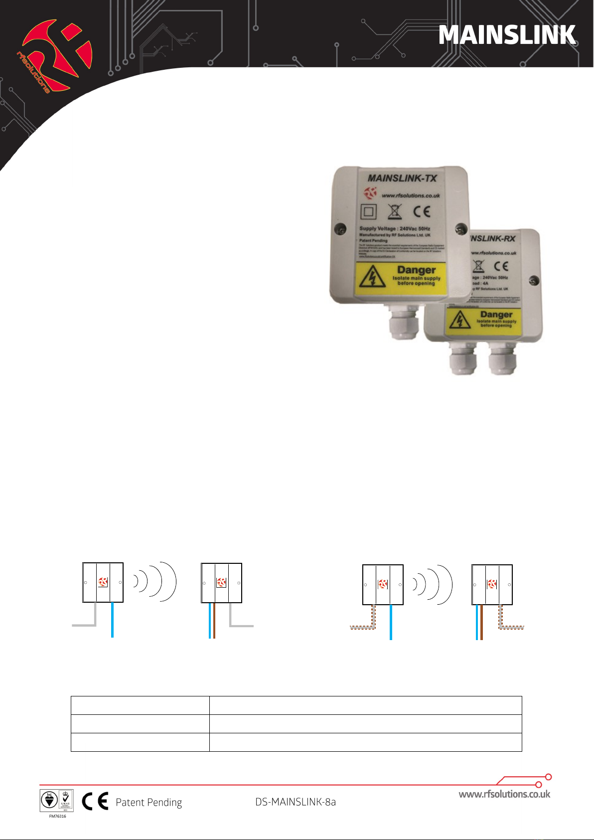
Supply Voltage TX/RX: 100 230 250 Vac
Quiescent Current:
TX: (negligible @230V <0.1uA)
RX: (Relay not operating - negligible
@230V <0.1uA)
~
0.1
(relay
operating)
uA
mA
Operating Frequency* 869.50 MHz
Maximum switching load (RX) 1000 W
Time delay from Tx on switch to Rx Relay
operation:
50 50 3000 mS
Time delay from Tx sw relax to Rx Relay
release:
50 50 3000 mS
RF Solutions Ltd. Recycling Notice
Meets the following EC Directives:
DO NOT
Discard with normal waste, please recycle.
ROHS Directive 2002/95/EC
Specifies certain limits for hazardous substances.
WEEE Directive 2002/96/EC
Waste electrical & electronic equipment. This
product must be disposed of through a licensed
WEEE collection point. RF Solutions Ltd., fulfils its WEEE
obligations by membership of an approved compliance
scheme.
Waste Batteries and Accumulators
Directive 2006/66/EC
Where batteries are fitted, before recycling
the product, the batteries must be
removed and disposed of at a licensed
collection point.
Environment Agency producer registration
number: WEE/JB0104WV.
Disclaimer:
Whilst the information in this document is believed to be correct at the time of issue, RF Solutions Ltd does not accept any liability whatsoever for its accuracy, adequacy or
completeness. No express or implied warranty or representation is given relating to the information contained in this document. RF Solutions Ltd reserves the right to make
changes and improvements to the product(s) described herein without notice. Buyers and other users should determine for themselves the suitability of any such infor-
mation or products for their own particular requirements or specification(s). RF Solutions Ltd shall not be liable for any loss or damage caused as a result of user’s own
determination of how to deploy or use R F Solutions Ltd’s products. Use of RF Solutions Ltd products or components in life support and/or safety applications is not author-
ised except with express written approval. No licences are created, implicitly or otherwise, under any of RF Solutions Ltd’s intellectual property rights. Liability for loss or
damage resulting or caused by reliance on the information contained herein or from the use of the product (including liability resulting from
negligence or where RF Solutions Ltd was aware of the possibility of such loss or damage arising) is excluded. This will not operate to limit or restrict RF Solutions Ltd’s
liability for death or personal injury resulting from its negligence.
Table of contents
Other RF SOLUTIONS Industrial Equipment manuals
Popular Industrial Equipment manuals by other brands

Nu-Tek
Nu-Tek NTM110LL-HW manual

Premier Manufacturing Co.
Premier Manufacturing Co. 1400 COUPLING Installation, Inspection, Operation & Maintenance Guide

AirVac
AirVac DRS27 user manual

Almaco
Almaco FLEXICOMPT AUTONOME+ user manual

Ebmpapst
Ebmpapst G1G133-DE19-02 operating instructions

Goldmedal
Goldmedal 2257 instruction manual