RFID ActiveRFID User manual

433.92 MHz
OperationsManual
This document is made available to ActiveRFID product owners and users for integration purposes. Proprietary and
confidential information is contained within; therefore this document is protected by all applicable international
intellectual property laws. The information contained in this document is constantly subject to revision (see Rev. number
at top of page).

Revision 06/2016
14190 E. Jewell Avenue Suite 4 Aurora CO 80012 TEL: 303-366-1234
www.rfidinc.com/activeRFID
ActiveRFID Operations Manual
2
Table of Contents
Product Description ....................................................................................................................................................4
Scope & Purpose.......................................................................................................................................................4
Summary...................................................................................................................................................................4
Product Identification................................................................................................................................................4
How To Contact Us...................................................................................................................................................4
Product Part Numbers & Accessories.........................................................................................................................4
Product Operations .....................................................................................................................................................6
Hardware Description ...............................................................................................................................................6
Reader .......................................................................................................................................................................6
Tags...........................................................................................................................................................................6
Quick Start Hardware Installation Guide....................................................................................................................7
Mounting the Reader.................................................................................................................................................7
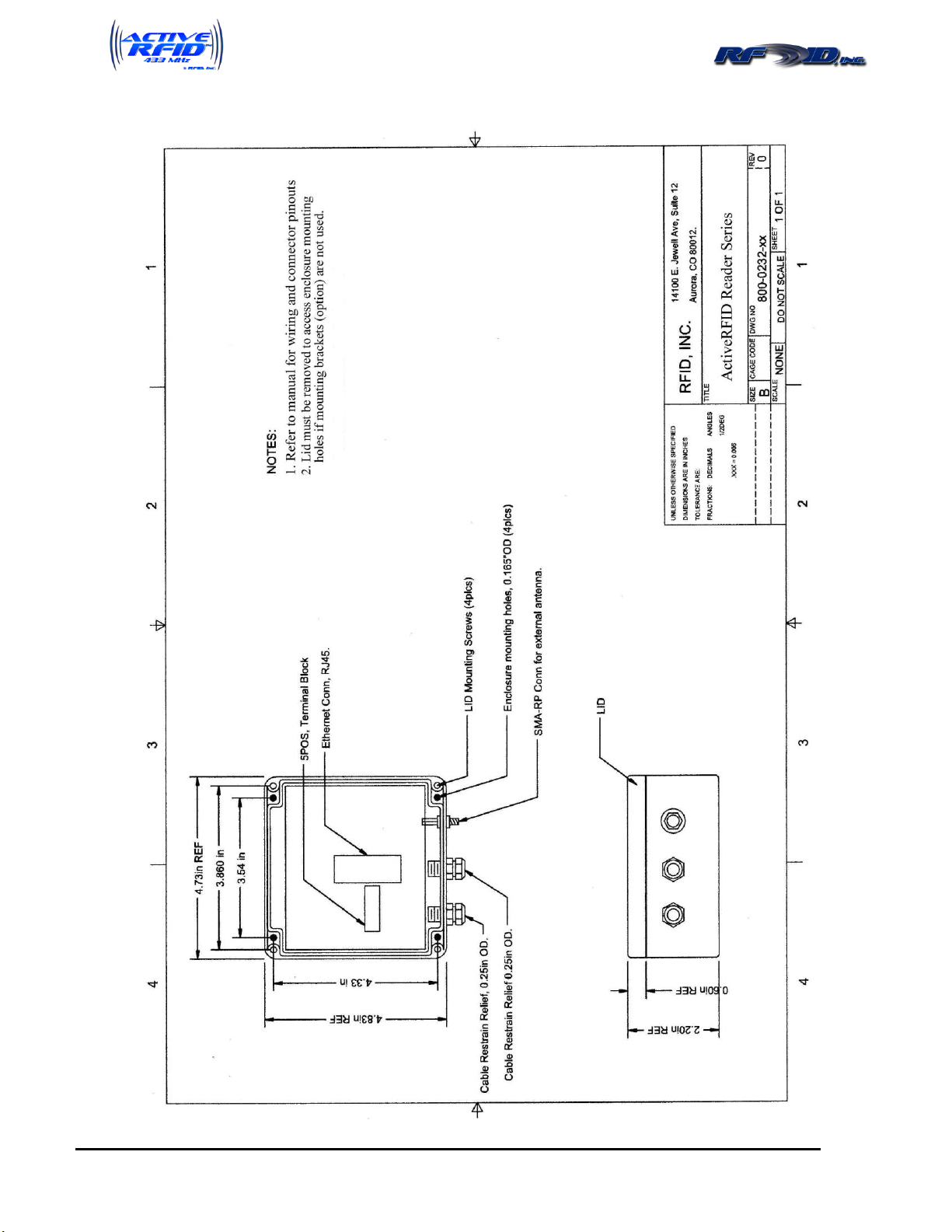
ActiveRFID Reader Drawing .....................................................................................................................................8
Cabling the Reader - Power ......................................................................................................................................9
Cabling the Reader - Communications .....................................................................................................................9
Mounting an External ANT-CP Flat Panel Directional Antenna..............................................................................9
Quick Start Operations Guide...................................................................................................................................10
Reading Tags...........................................................................................................................................................10
Interfacing the Reader to your PC –Serial (RS232, RS422, RS485 & USB) ........................................................10
HyperTerminal....................................................................................................................................................10
RFID, Inc. Terminal Program.............................................................................................................................10
Interfacing the Reader to your PC –Ethernet.........................................................................................................11
Configuring the XPORT with DeviceInstaller........................................................................................................11
HyperTerminal & Ethernet.................................................................................................................................14
Setting up the Reader................................................................................................................................................15
USB Port .................................................................................................................................................................15
Wire Specifications.............................................................................................................................................15
USB Connector...................................................................................................................................................15
USB Driver Installation......................................................................................................................................15
I/O PCBA Dipswitch Settings.................................................................................................................................17
Power Requirements...........................................................................................................................................18
Wire Specifications.............................................................................................................................................18
Wiegand Reader......................................................................................................................................................19
Wiegand Output..................................................................................................................................................19
Serial Reader (RS232/RS422/RS485).....................................................................................................................20
Setting RS485 Reader Addresses .......................................................................................................................20
Ethernet Reader.......................................................................................................................................................21

Revision 06/2016
14190 E. Jewell Avenue Suite 4 Aurora CO 80012 TEL: 303-366-1234
www.rfidinc.com/activeRFID
ActiveRFID Operations Manual
3
External Hardware Guide .........................................................................................................................................22
External Antenna.....................................................................................................................................................22
Relay Driver............................................................................................................................................................22
Loop Detector .........................................................................................................................................................22
Loop Detector Drawing...........................................................................................................................................23
Relay Drawing ........................................................................................................................................................24
Specifications..........................................................................................................................................................25
Tag Operating Specifications..................................................................................................................................25
Reader Operating Specifications.............................................................................................................................25
Tag Data and Reader Outputted Data Format...........................................................................................................26
Reader Commands and Responses ...........................................................................................................................27
[L] –Turn ON/OFF Flag Output ............................................................................................................................27
[R] –Turn ON/OFF RSSI Output...........................................................................................................................28
[CS] –Turn ON/OFF Checksum Output ................................................................................................................28
[D] - Duplicate Report Operating Mode.................................................................................................................28
[S] - Single Report Operating Mode Command......................................................................................................28
[Y] - Timeout of Buffered Memory Command ......................................................................................................29
[F] –Find a Specific Tag Only ...............................................................................................................................29
[C] –Report Tags only with a specific Facility Code.............................................................................................29
[P] –Polling Mode Command ................................................................................................................................30
[T] - Transfer Request (Polling) Command for a single Tag..................................................................................30
[TA] - Transfer Request (Polling) Command for all Tags in Buffer ......................................................................30
[Z] –Data Bit and Data Interval Time Lengths (for Wiegand usage only) ............................................................31
[Q] –Automatic Tuning of Tag Range...................................................................................................................31
[0] –(zero) Command to set Attenuation Gain manually.......................................................................................32
[4] –(four) Command to set Sensitivity manually..................................................................................................32
[403] & [000] –Clear all Attenuation Gain and Sensitivity Settings .....................................................................32
[6] –Ignore Tag command......................................................................................................................................33
[X] –Stop Data outputted from Reader..................................................................................................................33
[G] –Read Tag Flag Data.......................................................................................................................................33
[71] –Enable Relay.................................................................................................................................................33
[81] –Disable Relay................................................................................................................................................34
[91] –Trigger Relay................................................................................................................................................34
[J] –Relay Program Timer.......................................................................................................................................34
[LD] –Loop Detector Command.............................................................................................................................34
WARRANTY ...........................................................................................................................................................35
Appendix A...............................................................................................................................................................35
External Antenna Model ANT-CP Installation Instructions & Product Drawing ....................................................35

Revision 06/2016
14190 E. Jewell Avenue Suite 4 Aurora CO 80012 TEL: 303-366-1234
www.rfidinc.com/activeRFID
ActiveRFID Operations Manual
4
Product Description
Scope & Purpose
This document describes the physical characteristics, functional requirements and software features
contained in the ActiveRFID 433 MHz product. It lists the product specifications, as well as
environmental and operational criteria. The purpose of this document is to describe the ActiveRFID
features, functions and options. Included in this document will be details on the installation, the
operations and any other special considerations necessary to setup and operate the product.
Summary
ActiveRFID is the brand name for a new line of 433 MHz RFID Readers and Tags. Due to a number of
changes in the 433 MHz RFID marketplace, the time is right for the introduction of this exciting new
product line. We are a U.S. company comprised of seasoned RFID professionals, both engineers and
marketing specialists. We have designed a product line that is ideally suited to the AVI (Automated
Vehicle ID), Asset/Personnel Tracking, Perimeter Security, or identification of widgets through
manufacturing process markets.
Product Identification
To identify the ActiveRFID newly developed 433 MHz Active Tag, Reader, Wiegand IO PCBA, Serial
IO PCBA and Ethernet IO PCBA, the shipping documentation is marked with the complete model part
number and final assembly number.
How To Contact Us
303-366-1234 x101
Tech Support: 303-910-5447 cell 9am to 6pm PST
Sales: 719-330-2349 cell 7am to 5pm CST
Not Happy?
Need Immediate Results: Contact our President
303-378-9500 cell 7am to 9pm CST
Product Part Numbers & Accessories
Part Number
Model Number
Description
Transponders
800-0224-01
AT-CS
Clamshell/Windshield/Personnel Tag w/replaceable battery
800-0225-01
AT-MM
Metal Mount, black w/dog ear mounting w/replaceable battery
800-0226-01
AT-DC
Deck of Cards Potted IP69 weatherproof

Revision 06/2016
14190 E. Jewell Avenue Suite 4 Aurora CO 80012 TEL: 303-366-1234
www.rfidinc.com/activeRFID
ActiveRFID Operations Manual
5
800-0235-00
AT-OM
Omni-Directional, Potted IP69 weatherproof
800-0224-01-AU
AT-CS/AU
Clamshell Auto-Tune Tag
800-0225-01-AU
AT-MM/AU
Metal Mount Auto-Tune Tag
800-0226-01-AU
AT-DC/AU
Deck of Cards Potted IP69 Auto-Tune Tag
800-0235-00-AU
AT-OM/AU
Omni-Directional, Potted IP69 weatherproof Auto-Tune Tag
800-0224-01-ACL
AT-CS/ACL
Clamshell/Windshield/Pers Tag w/repl. Batt & Motion Sensor
800-0025-01-ACL
AT-MM/ACL
Metal Mount, black w/dog ears w/repl. Batt & Motion Sensor
800-0026-01-ACL
AT-DC/ACL
Deck of Cards Potted IP69 weatherproof w/Motion Sensor
800-0235-00-ACL
AT-OM/ACL
Omni-Directional, Potted IP69 weatherproof w/Motion Sensor
Readers
800-0230-30
ATR-RW
26 bit Wiegand Reader w/internal Antenna
800-0230-31/PJ
ATR-RW/PJ
26 bit Wiegand Reader w/internal Antenna & power jack
800-0231-30
ATR-RS
Serial Reader with internal Antenna
800-0231-31/9
ATR-RS/9
Serial Reader with internal Antenna & 9 PIN connector
800-0231-32/PJ
ATR-RS/PJ
Serial Reader with internal Antenna & power jack
800-0231-33/PJ9
ATR-RS/PJ9
Serial reader with internal Antenna, 9 PIN & power jack
800-0232-30
ATR-RE
TCPIP Ethernet Reader w/internal Antenna & RJ45 connector
800-0232-31/PJ
ATR-RE/PJ
TCPIP Ethernet Reader w/int. Antenna, RJ45 & power jack
Accessories
800-0233-12
ANT-CP-12
Directional Flat Panel Antenna w/12’ co-axial cable
800-0233-25
ANT-CP-25
Directional Flat Panel Antenna w/25’ co-axial cable
730-0038-10-AKIT
AKIT-10
Cable Kit, Active SMA-RP/N-TYPE 10 FT
730-0038-12-AKIT
AKIT-12
Cable Kit, Active SMA-RP/N-TYPE 12 FT
730-0038-25-AKIT
AKIT-25
Cable Kit, Active SMA-RP/N-TYPE 25 FT
730-0038-50-AKIT
AKIT-50
Cable Kit, Active SMA-RP/N-TYPE 50 FT
720-0004-01
PS12PJ
AC Power Supply, mating power jack, 12vdc 500mA
720-0004-04
PS12PT
AC Power Supply, pigtail wiring, 12vdc, 500mA
719-0071-00
EXY-SM
Small Yagi Antenna w/6’ cabling
719-0072-00
EXY-MD
Medium Yagi Antenna w/6’ cabling
719-0073-00
EXY-LG
Large Yagi Antenna w/6’ cabling
719-0070-02
ANT-WHIP6
Whip Antenna, 6”, Screw Mount, ¼ Wave Length
719-0300-30
AT-BatKit
Replacement battery & replacement peel & stick label
473-0085-00
AT-CS/BH
Badge Holder for CS Tag
Hand Held Reader
800-0240-30
ATR-3036E
Hand Held Reader, battery included, add PS12PJ as batt chgr
supply and charger

Revision 06/2016
14190 E. Jewell Avenue Suite 4 Aurora CO 80012 TEL: 303-366-1234
www.rfidinc.com/activeRFID
ActiveRFID Operations Manual
6
Product Operations
Hardware Description
This is a TTO (Tag talk only) Radio Frequency Identification system whereby the ActiveRFID Tag
transmits its data at factory set intervals to the Reader.
Reader
The Reader provides RF to digital translation of the signal produced by the ActiveRFID RF Electronic
Transponders, referred to herein as "Tags", when placed in the proximity of a Reader. The Reader
detects and filters data bits emitted from compatible RF Tags then converts bits into the associated
computer format of ASCII RS232/RS485, Wiegand, or Ethernet communications protocols. Advanced
error detection algorithms provide error-free operation.
Unlike similar systems, the Reader does not need an external Antenna, although external Antennas are
available to increase range. The PCB etched Antenna receives the Tag’s transmission. This saves greatly
in installation time and costs. The Reader can also operate on variable power sources of 8vdc to 28vdc.
Connection to the Reader is made using low-cost shielded twisted pair cables (22 AWG up to 21 feet,
above 21 feet 16 AWG is recommended) and easy to use angle entry screw terminal connectors further
simplify installation.
Tags
Standard Tags transmit their data signal in 1 of 2 standard time intervals, 1.5, or 2.0 seconds. The overall
time of Tag transmission is 4 milliseconds. Tags can be provided timed to transmit at any time interval
required. Faster time intervals lessen Tag battery life while longer intervals lengthen Tag battery life.
Talk to your ActiveRFID contact for more information.

Revision 06/2016
14190 E. Jewell Avenue Suite 4 Aurora CO 80012 TEL: 303-366-1234
www.rfidinc.com/activeRFID
ActiveRFID Operations Manual
7
Quick Start Hardware Installation Guide
Mounting the Reader
The Reader contains 4 mounting holes accessible by removing the lid. Note that these mounting holes
are located just to the inside of the 4 lid screws yet outside the lid gasket trace such that the integrity of
the IP67 housing for watertight purposes is not compromised. The diameter of the mounting screw holes
is 0.165” so be sure to use a screw of equal or lesser diameter. For best range performance, the Reader
should be oriented in a standing position, such that the PCB is perpendicular to the ground as depicted
below. If the Reader is to be mounted outside and exposed to various weather conditions, the cable
glands should be oriented down in order to prevent ingression of water from rain or snow. Also cables
should be coiled to create a drain loop below the Reader. What the Reader is mounted to makes little
difference, metallic or non-metallic, concrete, wood, metallic siding or a metal pole. Since most
applications require the Reader to be tuned to a specific range, the tuning functions will compensate for
the environment in which the Reader is placed. It should be noted that this is an IP67 rated box,
however once the cable glands were added for cabling entry, the box is no longer watertight or IP67
rated. To return the box to a watertight seal, apply Plumber’s putty or plumber’s tape to the cable glands
after wires are inserted but prior to re-tightening the cable glands.
Note: It is important to not feed both the power and communications lines through a single cable gland
as the gland will not tighten down well enough to maintain watertight integrity.

Revision 06/2016
14190 E. Jewell Avenue Suite 4 Aurora CO 80012 TEL: 303-366-1234
www.rfidinc.com/activeRFID
ActiveRFID Operations Manual
8
ActiveRFID Reader Drawing

Revision 06/2016
14190 E. Jewell Avenue Suite 4 Aurora CO 80012 TEL: 303-366-1234
www.rfidinc.com/activeRFID
ActiveRFID Operations Manual
9
Cabling the Reader - Power
The Reader is delivered with two power connection options, either with a quick connect single male pole
jack mounted in the Reader in place of the first cable gland shown above, or with the cable gland only.
Users ordering the quick connect jack probably also ordered the AC adaptable power supply which has a
mating connector. Users providing their own power will need to loosen the first cable gland, insert their
power wiring, apply Plumber’s Putty or Plumber’s tape and then re-tighten the cable gland. See page 18
for power and wiring specifications, and the illustrations on pages 19, 20and 21 for terminal connections.
Cabling the Reader - Communications
Wiegand –Use the second cable gland (center) to install Wiegand wiring and see the illustrations on
pages 19-21 for terminal connections.
Serial Users –The Reader is delivered with two connection options, either a 9 PIN serial connector
externally cabled to the box running through the second cable gland, or with bare pigtails wiring (tinned)
such that custom lengths of your own wiring can be added.
Ethernet users –An RJ45 connector is located on the inside of the Reader box at the center. It was not
possible to flush mount the connector in the side of the box for quick connection and still preserve the
watertight integrity. Users must run Ethernet cabling through the second cable gland then crimp or apply
their own RJ45 connector.
Mounting an External ANT-CP Flat Panel Directional Antenna
To cable the Reader to the external Antenna, all cabling and connections are provided. Simply use the
farthest right most connector on the Reader depicted in the photo above and follow the directions on how
to bypass the internal Antenna on page 22. Go to Appendix A on page 35.

Revision 06/2016
14190 E. Jewell Avenue Suite 4 Aurora CO 80012 TEL: 303-366-1234
www.rfidinc.com/activeRFID
ActiveRFID Operations Manual
10
Quick Start Operations Guide
Note1: Although a USB port exists for communication with the Reader for initial setup, it is not
necessary for users of Serial and Ethernet to install a USB drive and use the USB port. You can if you
like, but the same communications and setup can be accomplished via serial or Ethernet ports. Wiegand
users must use the USB port. There is a separate Quick Start Guide for Wiegand users.
Note2: This Quick Start section assumes the Reader is fully cabled and ready for operation. If not,
please cable the Reader using the instructions in this manual then return to this section.
Reading Tags
Simply plug the power supply into the Reader and into an AC outlet. At this point you will see a red
LED in the upper left corner of the PCBA illuminate solid, indicating power is on. If Tags are within
range you will hear a beep each time a Tag is read and the red LED will blink off and then back on with
each successive read. Congratulations, you have just successfully installed the Reader and are achieving
Tag reads. If there is more than 1 Tag within range all should be reading successfully.
Interfacing the Reader to your PC –Serial (RS232, RS422, RS485 & USB)
There are two options available, HyperTerminal or our own RFID, Inc. Terminal Program, a program
provided free of charge by RFID, Inc. Both a HyperTerminal link and our RFID, Inc. Terminal Program
should have been provided to you either on a CD ROM or via email.
HyperTerminal –Windows 7 and Windows Vista operating systems do not provide HyperTerminal. It
is possible to download HyperTerminal, and if this is an option you prefer, please contact RFID, Inc.
technical support and we will walk you through the download. For all other Windows operating
systems, HyperTerminal is provided as standard and executing the link provided will bring a
HyperTerminal screen up with all the Reader’s factory default settings preset in HyperTerminal
Properties except for the appropriate COM port. Since we do not know your COM port, we cannot
predefine this for you. With the Reader plugged into your PC’s COM port, apply power to the Reader
and you will see a start up message similar to this:
RFID Inc
(0180)-v.1.07
Tags should begin reporting to your HyperTerminal screen and the Reader should begin beeping
(reading Tags). If nothing appears on your screen, change your COM port. In order to do so, select the
Disconnect icon, then File, Properties, pull down and select the correct COM port, select OK, then select
the Call icon. You must disconnect and reconnect in this fashion each time in order for HyperTerminal
to recognize the change of COM port.
RFID, Inc. Terminal Program –Open the zip file named SetupRFIDTerm that should have been
provided to you. In this file are two files names setup.exe and SetupRFIDTerm.msi. Copy these two
files to a folder where you would like to store them, and then copy the files to that folder. Go to the

Revision 06/2016
14190 E. Jewell Avenue Suite 4 Aurora CO 80012 TEL: 303-366-1234
www.rfidinc.com/activeRFID
ActiveRFID Operations Manual
11
folder and execute the setup.exe file, then follow the prompts. Once installed, there should be a new
icon on your desktop named RFID Terminal.exe. Double click on it to begin the program. Pull down
and select your COM port, then choose “Connect.” If the Reader is powered and connected to your PC,
you should begin seeing Tag reads appear. This program is so simple to use, there are no further
directions herein. Instead of having to type commands in, they can simply be selected. If there are parts
of this program that do not make sense to you, you will understand them after having read the remainder
of this manual.
Interfacing the Reader to your PC –Ethernet
This is a standard TCP/IP Ethernet device employing a Lantronix XPort Ethernet modem. It will be
necessary to load a program termed DeviceInstaller (included in a separate WinZip file) in order to setup
your preferred properties.
Specifications:
Protocol: TCP/IP
Connectors: RJ45
Serial Baud rate: 10 Base-T or 100 Base-TX (auto-sensing)
Maximum cable run: 2000’
Configuring the XPORT with DeviceInstaller - Open the zip file named DeviceInstaller that
should have been provided to you. This program will assist you in the setup of the Ethernet Interface.
Unzip and extract the files contained to your PC. Go to the folder you extracted the files to and execute
the setup.exe file. Note; if you receive the following message:
---------------------------
Windows Installer Loader
---------------------------
This setup requires the .NET Framework version 1.1.4322. Please install the .NET Framework and run
this setup again. The .NET Framework can be obtained from the web. Once the download is found you
will be prompted, “Would you like to do this now?”
---------------------------
Say yes and download the file to the same folder you chose for the DeviceInstaller then execute the .Net
Framework setup.exe file you just downloaded and follow the prompts. Then go back to original
setup.exe file for DeviceInstaller and follow the prompts to install the files in a Lantronix folder under
Programs.
Connect the Reader to an Ethernet port, not your laptop or PC, but the same network your laptop or PC
is connected, then power the Reader. Verify the light on the left of the Ethernet connector is either solid
orange or solid green. Go to your Programs folder under Lantronix and execute the Application File
“DeviceInstaller.exe.” Then click the search button and wait for DeviceInstaller to find your device.

Revision 06/2016
14190 E. Jewell Avenue Suite 4 Aurora CO 80012 TEL: 303-366-1234
www.rfidinc.com/activeRFID
ActiveRFID Operations Manual
12
If your device is found, a folder named XPort will appear; expand it to expose the firmware version and
expand it one more time to expose its IP address. Navigate to the IP ADDRESS, select it. 3 tabs will
appear on the right. Device Details, Web Configuration, and Telnet Configuration; select Web
Configuration and click the green button labeled GO. A password window will pop up. Leave it blank
and click OK.
Select Serial Settings, change the baud rate to match that of the serial port (default 9600), check enable
packing, select 12msec idle gap time. Upon completion the next screen should look like that below.
Scroll down and click the OK button. While there is still a “Done!” label next to the OK button select
Connection on the left to change pages.

Revision 06/2016
14190 E. Jewell Avenue Suite 4 Aurora CO 80012 TEL: 303-366-1234
www.rfidinc.com/activeRFID
ActiveRFID Operations Manual
13
Change local port to 2000 and click OK, while the “Done!” is still present by the OK button click on the
Apply settings link on the left.

Revision 06/2016
14190 E. Jewell Avenue Suite 4 Aurora CO 80012 TEL: 303-366-1234
www.rfidinc.com/activeRFID
ActiveRFID Operations Manual
14
This is what it should look like while the settings are being applied.
Once the Reader is done updating the settings, turn the unit off for 5 seconds and then back on. Wait
until the light on the left of the Ethernet connector is stable and solid and then go back to the
DeviceInstaller program and click search. Follow the same steps you used to change Serial and
Connection settings, however this time do not click OK. You are simply verifying the changes have
taken effect. Setup is finished. If you like, you can use HyperTerminal to test communications with the
reader.
HyperTerminal & Ethernet - Open a HyperTerminal session (Start, Programs, Accessories,
Communications, HyperTerminal). Name your new connection and choose an icon. On the last pull
down menu “Connect using:” select “TCP/IP Winsock.” The next box will prompt Host Address, enter
the TCPIP address of the Reader and under Port Number enter 2000, then select the Settings tab, then
ASCII Setup. Check the box “Echo typed characters locally” then select OK and save. You should not
only be able to see Tags reads reporting to your screen but should be able to issue commands to the
Reader as well. Test this by entering open square bracket and close square bracket which should result
in a question mark being returned.

Revision 06/2016
14190 E. Jewell Avenue Suite 4 Aurora CO 80012 TEL: 303-366-1234
www.rfidinc.com/activeRFID
ActiveRFID Operations Manual
15
Setting up the Reader
This section contains information for configuring the Reader’s power and signal cabling. Power and
communications are provided through a cable gland at the bottom of the Reader. To access the inside of
the Reader assembly, simply remove the 4 screws at each corner of the Reader housing’s lid.
Following installation of all Readers wiring, the lid should be reinstalled and the cable glands tightened.
For further moisture integrity, Plummer’s tape or putty can be applied to the cable glands.
USB Port
In general, cables have only plugs, and hosts and devices have only receptacles. Hosts almost universally
have type-A receptacles, and devices one or another type-B variety. Type-A plugs mate only with type-A
receptacles, and type-B with type-B; they are deliberately physically incompatible.
Wire Specifications
The maximum length of a standard USB cable (for USB 2.0 or earlier) is 5.0 meters (16.4 ft). The
primary reason for this limit is the maximum allowed round-trip delay of about 1,500 ns. If USB host
commands are unanswered by the USB device within the allowed time, the host considers the command
lost
USB Connector
Plug the Type A plug from one end of the cable into the Type A connector located on your computer.
Plug the Type B plug from the other end of your cable into the Type B connector located on the Reader
PCBA (see picture below).
USB Driver Installation
Note: Serial and Ethernet users need not use the USB connection to setup Reader however it is an option
prior to having wired the serial or Ethernet connections. Once you plug in the USB cable to both the
computer and the ActiveRFID Reader, you now power up the computer. Once the computer is fully
powered and connected to the Reader via the USB port, power up the ActiveRFID Reader. Your
computer will then display that new hardware is found and Figure 1 below will be displayed. Select the
“Yes, this time only” option then press “Next>” to continue. At this point Figure 2 should be displayed
and you then select “Install the software automatically (Recommended)” then press “Next>” to continue.

Revision 06/2016
14190 E. Jewell Avenue Suite 4 Aurora CO 80012 TEL: 303-366-1234
www.rfidinc.com/activeRFID
ActiveRFID Operations Manual
16
The software will then start looking for the appropriate drivers for the USB device and Figure 3 will then
be displayed (which may also say “?USB Serial Port”). Once the Driver is found and installed, Figure 4
will then be displayed, showing that the driver is installed properly.
If your computer cannot find the necessary USB driver, instead of searching the internet for the
appropriate driver, we have included both 32 bit and 64 bit USB drivers to you either on CD ROM or via
email. To find out whether your computer is operating on 32 or 64 bits, from your desktop right click on
My Computer and select Properties. If there is no My Computer icon on your desktop, go to your
Control Panel via the Start menu and select System. Either way, in figure 2 below you will need to
choose “Install from a list or specified location”, choose the location you saved the USB Drivers we
supplied to you, and continue.
Figure 1
Figure 1Figure 2
Figure 4
Figure 3

Revision 06/2016
14190 E. Jewell Avenue Suite 4 Aurora CO 80012 TEL: 303-366-1234
www.rfidinc.com/activeRFID
ActiveRFID Operations Manual
17
I/O PCBA Dipswitch Settings
There are a series of 8 switches on the left hand side of the Reader PCBA, as depicted below. All three
I/O PCBA’s, Wiegand, Serial and Ethernet, use this 8 position dipswitch to set and control Reader
functions. Switch positions are exactly opposite of those numbered on the device. When a switch is up,
it is considered on, and off when it is positioned down.
1. Auto Range Tuning –There are two methods of Auto Range Tuning, one via software command as
discussed on page 31, and one via use of this switch. If you are in possession of a Master Range
Tuning Tag, this is a Tag programmed with all 5’s, you can position that Tag the required distance
from the Reader and then with power on the Reader move switch 1 to the on position and then back
down to the off position. The Reader will then begin to cycle itself through levels of db power until
it has reached a level sufficient to read the Master Range Tuning Tag. In layman’s terms, the Reader
is stepping out several feet at a time in distance until it reaches the range of the Master Range Tuning
Tag, then the Reader will stop and set itself for this distance (db gain actually). This process can be
immediate or take several minutes to complete. An audio tone will indicate the process has
completed, the Reader will return to normal operations and Tags within range will begin to be read.
Note: Environments differ in the amount of surrounding metal and sources of interference. Tuning
a Reader to 10’ in a lab environment may not equate to 10’ of tuned range when installed elsewhere.
It is always optimal to tune the Reader in its actual environment.
2. Beeper –Position switch #2 up to turn the beeper (audio indicator) off, and down for the beeper to
remain on.
Switch positions 4 through 8 are used to set communications settings and should be self explanatory
given the tables below.
3. Not used.

Revision 06/2016
14190 E. Jewell Avenue Suite 4 Aurora CO 80012 TEL: 303-366-1234
www.rfidinc.com/activeRFID
ActiveRFID Operations Manual
18
4. Serial settings
5. Serial settings
SW4
SW5
Result
OFF
OFF
RS232
ON
ON
RS485
ON
OFF
RS422
6. Baud rate settings
7. Baud rate settings.
8. Baud rate settings.
SW8
SW7
SW6
Baud Rate
OFF
OFF
OFF
1200
ON
OFF
OFF
2400
OFF
ON
OFF
4800
ON
ON
OFF
9600
OFF
OFF
ON
19200
ON
OFF
ON
38400
OFF
ON
ON
57600
ON
ON
ON
115200
Power Requirements
The Reader can be powered from regulated, linear, or switching power sources having the characteristics
defined in the Specifications section of this document (7 to 24 volts). RFID, Inc. can provide a power
supply suitable for use with the Reader. The Reader should be operated from a grounded supply that has
the same ground reference as the host computer. The positive power connection and the ground
connection are applied to the Reader at the left most terminal block, just to the right of the Dipswitches
block, (see Figure 9 below).
Wire Specifications
Shielded (22 AWG for communication cable length up to 25’ and 16 AWG for communication lengths
beyond 25’) insulated, stranded wire is recommended and all wires should be stripped approximately 3/8
inches and tinned. Whatever cable is selected, it should fit within the range allowed by the cable gland
providing wire access to the Reader. The cable gland will accommodate diameters of .090 to .265 inches.

Revision 06/2016
14190 E. Jewell Avenue Suite 4 Aurora CO 80012 TEL: 303-366-1234
www.rfidinc.com/activeRFID
ActiveRFID Operations Manual
19
Wiegand Reader
Figure 9
Wiegand Output
This is a 26 bit standard Wiegand protocol with Data 0 and Data 1 normally resting at zero voltage and
moving to +5 volts on logic 0 or logic 1. The single line voltage rests at 2.5 volts and pulses to +5 volts
for logic 1 and down to 0 volts for logic zero. The Reader is defaulted to a bit length in time of 30
microseconds and bit interval in time of 150 microseconds, which are also the minimum times available.
The maximum bit length is 100 microseconds and the maximum bit interval is 1000 microseconds.
These settings are held in non-volatile memory. See the Programming Section of this document for
modifying these settings. For wiring the Data 0 and Data 1 Wiegand wire to the Reader, see picture
above.

Revision 06/2016
14190 E. Jewell Avenue Suite 4 Aurora CO 80012 TEL: 303-366-1234
www.rfidinc.com/activeRFID
ActiveRFID Operations Manual
20
Serial Reader (RS232/RS422/RS485)
Figure 10
Setting RS485 Reader Addresses
Since the architecture of an RS-485 enabled system dictates linking Readers together in a multi-drop
single network channel, it is necessary to assign the Reader an address thus allowing your controller or
host computer to know with which Reader it is communicating. This is accomplished by use of the
RS485 Switches 1 & 2 in the upper right hand corner of the PCBA, see photo above (Figure 10). These
switches are two black squares with white adjustable centers. The white centers have an arrow thus when
turned point to a specific number on the black square. The first square (top) designates the first
numerical address character when addressing from 0 to 31 while the second square (bottom) designates
the second numerical address character. Thus placing the top block’s center arrow to 3 and the bottom
block’s arrow to 1 designates an address 31. Valid addresses range from 00 to FF.
Table of contents
Popular Pet Care Product manuals by other brands

Evolution Dog Wash
Evolution Dog Wash Evolution Owner's/operator's manual

Petainer
Petainer PET916N user manual

E-Collar
E-Collar Einstein BarkLess BL-100 owner's manual

Dogtra
Dogtra 150NCP owner's manual

AniOne
AniOne Chase, Hide & Catch Instructions for use

Zoovilla
Zoovilla Merry Products PTF0051720800 manual