RFM XG2510HE User manual

RF Monolithics, Inc.
XG2510HE Gateway/Manager
Hardware and Configuration Guide
WirelessHART

XG2510HE MANAGER HARDWARE AND CONFIGURATION GUIDE

Contents
XG2510HE MANAGER HARDWARE AND CONFIGURATION GUIDE i
About This Guide
Related Documents ............................................................ iii
Conventions Used............................................................... iii
1Introduction
What is a SmartMesh Network?.........................................1
SmartMesh Network Features ................................................2
XG2510HE Gateway/Manager’s Role .......................................2
XG2510HE Packing List ......................................................3
XG2510HE Overview ...........................................................3
10/100Base-T Ethernet Interface ...........................................4
Serial 1 Interface .................................................................5
Serial 2 Interface .................................................................6
2 Specifications
Detailed Radio Specifications.............................................7
Antenna Specifications .......................................................8
Power Supply.......................................................................8
Mechanical Drawings ..........................................................9
Regulatory and Standards Compliance ........................... 10
Normal Operating Conditions........................................... 10

TABLE OF CONTENTS
ii XG2510HE MANAGER HARDWARE AND CONFIGURATION GUIDE
3 Installing the XG2510HE
Ports Used by the XG2510HE ........................................... 11
Connecting the XG2510HE Directly to a Computer ........ 12
Installing the XG2510HE on a LAN.................................. 13
A Configuring Serial 1 Operation
Configuring the Serial 1 Interface ................................... 15
Using Admin Toolset to Configure Serial 1 .............................15
Using Linux Commands to Configure Serial 1 ......................... 17
B Assembling a 9-pin D-SUB Adapter for Serial 1
C Restoring XG2510HE Factory Default Settings

XG2510HE MANAGER HARDWARE AND CONFIGURATION GUIDE iii
About This Guide
This guide provides an overview of the hardware and software resources of the
XG2510HE WirelessHART gateway/network manager The guide also includes
specifications and configuration information.
Related Documents
This guide is a part of a documentation suite for the XG2510HE gateway/manager. The
following documents contain additional information to support software and firmware
development for use with an XG2510HE gateway/manager:
•XG2510HE Gateway/Manager Serial API Guide - provides information about
manager’s packet-based API and instructions on configuring the serial port
application function.
•XG2510HE Gateway/Manager XML API Guide - provides information about
manager’s hierarchical tag-based XML API.
•XG2510HE Gateway/Manager CLI Commands Guide - describes manager’s CLI
commands, used for debugging and troubleshooting.
Conventions Used
The following conventions are used in this guide:
•Computer type indicates information that you enter, such as specifying a URL.
•Bold type indicates buttons, fields, and menu commands.
•Italic type is used to introduce a new term.
Note: Notes provide more detailed information about concepts.
Caution: Cautions advise you about actions that might result in a loss of data.
Warning! Warnings advise you about actions that may cause physical harm to the
hardware or your person.
WirelessHARTis a registered trademark of the HART Communication Foundation.
SmartMesh IA-510(H)TM is a trademark of DUST Networks, Inc.

ABOUT THIS GUIDE
iv XG2510HE MANAGER HARDWARE AND CONFIGURATION GUIDE

XG2510HE MANAGER HARDWARE AND CONFIGURATION GUIDE 1
1
Introduction
RFM’s XG2510HE WirelessHART gateway/network manager is based on Dust
Networks’ SmartMesh IA-510(H)TM protocol. The XG2510HE is designed to manage a
network of RFM’s XDM2510H radio modules that use Dust Networks’ low power radio
technology. In combination, these products provide carrier class data reliability, low
latency, and deterministic power management that is required for the industrial
automation market. The XG2510HE acts as both as a gateway and network manager for
up to 250 XDM2510H modules (motes), creating a self-configuring, reliable wireless
mesh network.
What is a SmartMesh Network?
SmartMesh networks are reliable, ultra low-power wireless mesh networks that can be
used for a wide variety of monitoring applications, including building automation,
industrial monitoring, and remote site security. A SmartMesh network consists of a
network manager and up to 250 low-power wireless transceivers that have connections
for analog, digital, and serial sensors and actuators.
Figure 1 An XG2510HE - XDM2510H Network
•XG2510HE Gateway/Manager - a line powered network node that controls and
monitors network performance.
The XG2510HE coordinates routing, aggregates
XDM2510H packets, collects network statistics, and publishes data to a wired
network.
The XG2510HE can publish data in XML format over the Ethernet port,
or in serial format over the serial port.
XDM2510H
XDM2510H
XG2510HE
LAN/
WLAN
PC

CHAPTER 1 - INTRODUCTION What is a SmartMesh Network?
2 XD2510HE MANAGER HARDWARE AND CONFIGURATION GUIDE
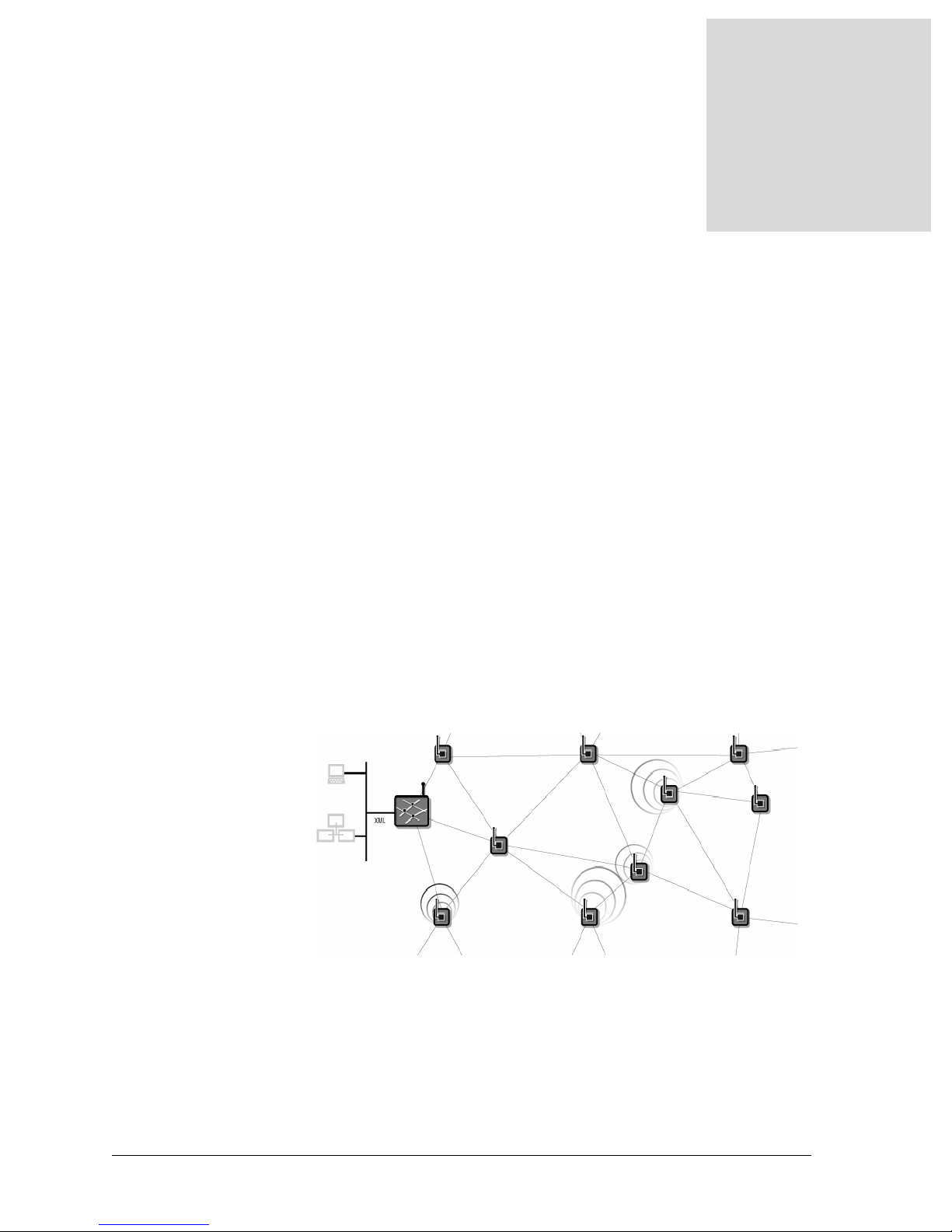
•XDM2510H modules -ultra low-power wireless transceivers that receive serial
data from attached sensors and use an onboard radio to send the packets to
neighboring modules. These modules pass the packet on to other modules as
needed, and, in a series of “hops” deliver the data to the manager. XDM2510H’s
run SmartMesh software and are designed as simple-to-integrate wireless modules.
SmartMesh Network Features
SmartMesh networks provide a simple, reliable way to monitor and control processes
and equipment. Using redundant, multi-hop networking and ultra low-power hardware,
SmartMesh networks offer unprecedented access to information about the physical
world.
XG2510HE-XDM2510H SmartMesh networks are:
•Easy to Install - They are self-configuring, battery-powered networks that require
no site survey or wireless expertise to install.
Benefit: You can deploy a SmartMesh Network within hours, not days.
•Reliable - They provide redundant, self-healing routing that approaches the
reliability of a wired network.
Benefit: You have the reliability of a wired network with the flexibility of wireless.
•Manageable - They provide network-wide quality-of-service metrics and control
commands that simplify network management.
Benefit: You can manage multiple networks from a single PC. No device-level
coding or management is needed.
XG2510HE Gateway/Manager’s Role
The XDM2510E gateway/manager provides configuration, management and gateway
functionality for a network of XDM2510H transceiver modules. At its core, the
XG2510HE utilizes a SmartMesh IA-510 embedded manager, which includes a
wireless transceiver, processor and memory, embedded networking software, and
multiple interfaces to host systems, including PPP and Ethernet.
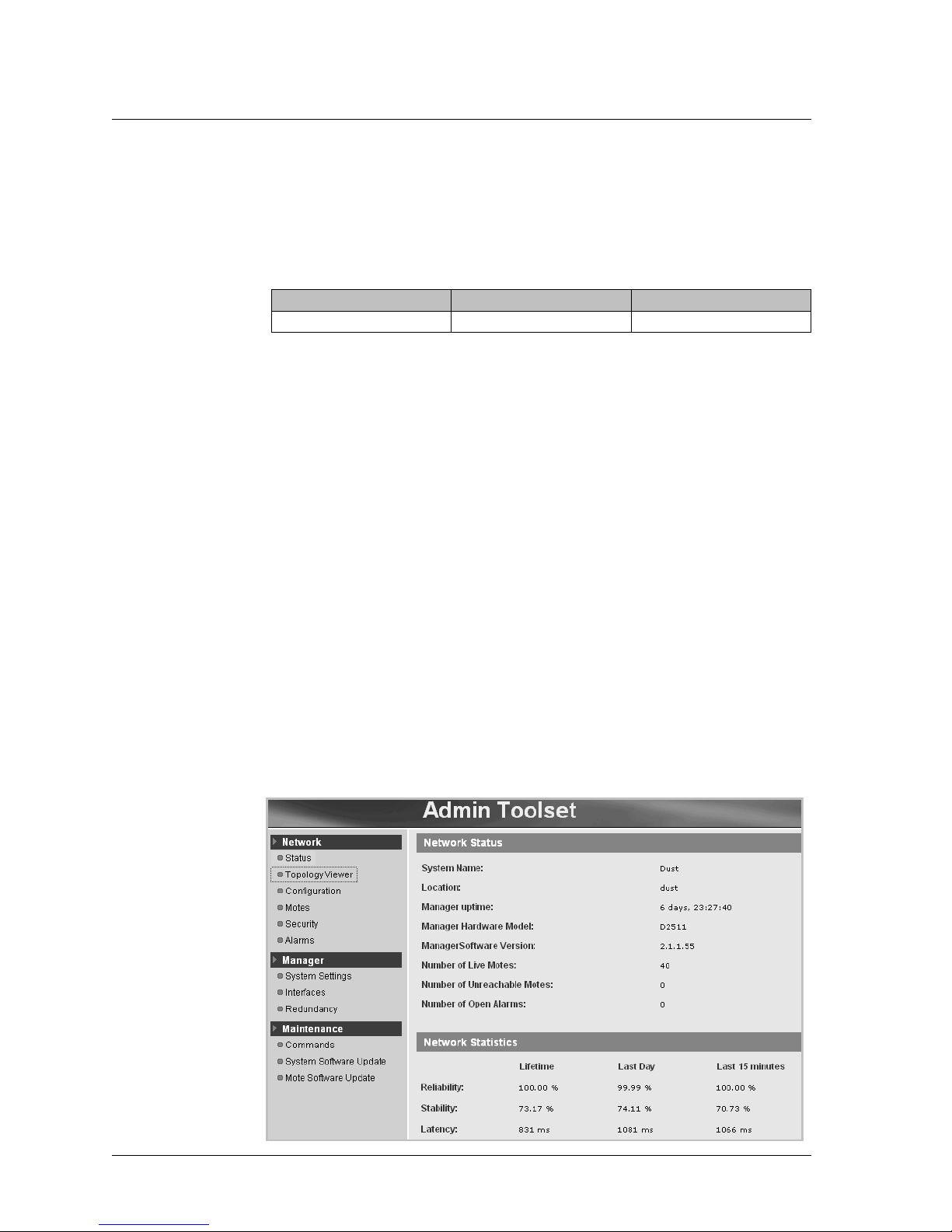
XG2510HE gateway/managers host well defined application interfaces (via both XML
API and serial API) that allow programmatic access to network control commands,
performance statistics, and connectivity details. In addition, the XG2510HE offers
administrative interfaces via its Web-based Admin Toolset utility and text-based
command line interface (CLI).

XG2510HE Packing List CHAPTER 1 - INTRODUCTION
XD2510HE MANAGER HARDWARE AND CONFIGURATION GUIDE 3
XG2510HE Packing List
The components shipped with the XG2510HE gateway/manager are listed in Table 1.
XG2510HE Overview
The XG2510HE provides a 10/100Base-T Ethernet interface and three serial interfaces,
a power supply connector, and status LEDs, as shown in Figure 2. The data interfaces
are described in detail in the following sections. For power supply specifications, refer
to Chapter 2.
The status LEDs provide the following information:
•Power (Green) - The Power LED is on when the 12 V power supply provided with
the D2511 is connected and functioning properly.
•Subscription (Yellow) - Indicates that a client program is subscribed to the
manager via Ethernet or the Serial 1 interface.
•Radio (Yellow) - Blinks when there is data activity over the radio.
Figure 2 XG2510HE Features
Table 1 Packing List for the XG2510HE Manager
Component Amount Description
XG2510HE 1 Controls and monitors the network.
Power cable 1 Connects the manager to an AC outlet.
International adapter kit 1 The kit includes power adapters for most
countries.
P o w e r
C o n n e c t o r
E t h e r n e t
P o r t
S e r i a l 1
P o r t
S e r i a l 2
P o r t
S e r i a l 3
P o r t

CHAPTER 1 - INTRODUCTION XG2510HE Overview
4 XD2510HE MANAGER HARDWARE AND CONFIGURATION GUIDE
10/100Base-T Ethernet Interface
The 10/100Base-T Ethernet interface is a standard RJ45 connector which provides users
with access to manager’s XML-RPC API and the Admin Toolset utility.
Note: The Ethernet interface must be connected before the XG2510HE is powered on in
order for Linux to recognize the Ethernet port.
XML-RPC API
The XML-RPC API is an open Extensible Markup Language (XML) interface that lets
a client application send Remote Procedure Call (RPC) requests to the gateway/
manager and receive responses and other data from the manager via XML-RPC. The
API consists of a Control Channel and a Notification Channel. The Control Channel is
used to establish connection and exchange commands and information about the
SmartMesh Network. The Notification Channel is used to stream data and network
events to the client program. The API is documented in the XG2510HE Gateway/
Manager XML API Guide.
Admin Toolset
The XG2510HE provides a Web-based administrative tool, called Admin Tool-set (see
Figure 3), which can be used to view network statistics and module (mote) and alarm
information, configure serial and Ethernet port settings, configure the Real Time Clock
or enable the Network Time Protocol (NTP) server, set the network security mode, and
execute selective commands. You can also use Admin Toolset to upgrade the software
and perform remote software updates on XDM2510H modules in the wireless network.
The Admin Toolset utility is described in detail in the XG2510HE Gateway/Manager
Admin Toolset Guide.
Figure 3 Admin Toolset
Table 2 Ethernet Port Hardware Specifications
Port Description Signaling
Ethernet 10/100Base-T Ethernet IEEE 802.3 10/100Base-T

XG2510HE Overview CHAPTER 1 - INTRODUCTION
XD2510HE MANAGER HARDWARE AND CONFIGURATION GUIDE 5
Serial 1 Interface
The Serial 1 interface (RJ45 connector) provides programmatic access for
configuration, management, and data access to the XG2510HE. The interface can be
used for one of two functions:
•To access the manager using Point-to-Point Protocol (PPP)
•To access the serial API associated with the XG2510HE
The following sections describe the Serial 1 functions in greater detail. Instructions for
configuring the Serial 1 are provided Appendix A.
Note: An adapter is required for the Serial 1 interface if you are connecting to a PC or
other control device that uses a 9-pin D-SUB RS232 port. See Appendix B for
information on assembling an RJ45 to 9-pin D-SUB adapter.
PPP
The manager allows IP connection through the Serial 1 port using Point-to-Point
Protocol (PPP). This connection provides access to the same interfaces that are available
through the Ethernet interface, such as the XML API and the Admin Toolset utility. The
manager acts as a PPP server. Note that the client is responsible for periodically pinging
the XG2510HE and re-establishing PPP connection if necessary. Table 5 provides
specifications for the PPP interface.
Table 3 Serial 1 Interface Hardware Specifications
Port Description Signaling
Serial 1 UART 5-pin RS232 levels
Table 4 RJ45 Connector Pinout
Pin Signal
Name Signal
Description
1 RI Ring Indicator
2 DCD Carrier Detect
3DTR DataTerminal
Ready
4 GND Signal Ground
Common
5 RXD Receive Data
6 TXD Transmit Data
7CTS ClearToSend
8 RTS Request To Send
Figure 4 RJ45 Connector

CHAPTER 1 - INTRODUCTION XG2510HE Overview
6 XD2510HE MANAGER HARDWARE AND CONFIGURATION GUIDE
Serial API
The manager provides a packet-based serial API that allows communications over its
asynchronous Serial 1 interface. For more information about the Serial API, refer to the
XG2510HE Gateway/Manager Serial API Guide. See Appendix A in this guide for
instructions on configuring the Serial 1 port for the Serial API.
Serial 2 Interface
The Serial 2 interface (9-pin D-SUB female connector) allows access to manager’s
command line interface (CLI) through RS232. The CLI can be used to set the
configuration of the Serial 1 interface and for troubleshooting with the assistance of
RFM techincal support. Appendix A provides instructions on using the CLI to set the
Serial 1 configuration.
Figure 5 9-pin D-SUB Female Connector
Serial 3 Interface
The Serial 3 interface is reserved for future use.
Table 5 PPP Interface Specifications
Parameter Value
Serial port data rate 115 kbps, 8 bits, no parity, 1 stop bit
Authentication required None
Header compression PPP header compression
Data compression supported PPP deflate compression
(preferred), BSD compression
IP addresses Settable during connection
Default XG2510HE (server) 192.168.101.10
Default client 192.168.101.11
Table 6 Serial 2 Port Hardware Specifications
Port Description Signaling
Serial 2 UART 9-pin RS232 levels

XG2510HE MANAGER HARDWARE AND CONFIGURATION GUIDE 7
2
Specifications
This chapter provides specifications, mechanical drawings and certification information
for the XG2510HE gateway/manager.
Detailed Radio Specifications
Table 7 XG2510HE Radio Specifications
Parameter Min Typ Max Units Comments
Operating frequency 2.4000 2.4835 GHz
Number of channels 15
Channel separation 5 MHz
Occupied channel
bandwidth 2.7 MHz At -20 dBc
Frequency accuracy -40 +40 ppm
Modulation
IEEE 802.15.4 DSSS
Raw data rate 250 kb/s
Receiver operating input
level 0dBm
Receiver sensitivity -92.5 dBm At 50% PER, 25 °C
-90 dBm At 1% PER, 25 °C,
(
inferred from 50%
PER measurement)
Output power, EIRP
PA* enabled
PA* disabled +10
0dBm
dBm
See “Antenna
Specifications”
Range**
PA* enabled 25 °C, 50% RH, 1
meter above
ground, +2 dBi
omni-directional
antenna
Indoor 100 m
Outdoor 300 m
PA* disabled
Indoor 25 m
Outdoor 200 m
* PA = power amplifier
** Actual RF range performance is subject to a number of installation-specific
variables including, but not restricted to ambient temperature, relative humidity,
presence of active interference sources, line-of-sight obstacles, near-presence of
objects (for example, trees, walls, signs) that may induce multipath fading. As a
result, actual performance varies for each instance.

CHAPTER 2 - SPECIFICATIONS Antenna Specifications
8 XG2510HE MANAGER HARDWARE AND CONFIGURATION GUIDE
Antenna Specifications
The antenna provided on the XG2510HE gateway/manager meets the specifications in
Table 8. For optimum performance, position the antenna vertically when gateway/
manager is installed.
Power Supply
A universal power supply is included with each XG2510HE gateway/manager. The
output of the transformer is 12 V at 1.1 Amps DC, and it is connected to + (positive) and
-(ground) terminals of the connector. However, any DC supply with an output of 9 to 30
V at 0.5 Amps can be connected. A 24 VAC supply can be connected to the two right-
most terminals of the connector (see Figure 6). The power supply connector uses a
Phoenix PN 1757048 or equivalent mating connector.
Figure 6 Power Supply Connector
Table 8 XG2510HE Antenna Specifications
Parameter Value
Frequency range 2.4-2.4835 GHz
Impedance 50 Ω
Gain +2 dBi maximum
Pattern Omni-directional
2 4 V A C
I n p u t P i n s
9 - 3 0 V D C
I n p u t P i n s

Mechanical Drawings CHAPTER 2 - SPECIFICATIONS
XG2510HE MANAGER HARDWARE AND CONFIGURATION GUIDE 9
Mechanical Drawings
Figure 7 Dimensions of the XG2510HE Manager

CHAPTER 2 - SPECIFICATIONS Regulatory and Standards Compliance
10 XG2510HE MANAGER HARDWARE AND CONFIGURATION GUIDE
Regulatory and Standards Compliance
Installation and Operation
The antenna used for the XG2510HE transmitter must be installed to provide a
separation distance of at least 20 cm from all persons and must not be co-located or
operated in conjunction with any other antenna or transmitter. Installers and end-users
must be provided with antenna installation instructions and transmitter operating
conditions for satisfying RF exposure compliance.
FCC Compliance
FCC Testing
The XG2510HE is certified as complying with Part 15.247 of FCC rules and
regulations, CFR Title 47, Part 15, Subpart B.
IC Compliance
IC Testing
The XG2510HE is certified as complying with Industry Canada (IC) RSS-210
Regulations. The XG2510HE also complies with IC ICES-003.
CE Compliance
Declaration of Conformity
RF Monolithics, Inc., 4441 Sigma Road, Dallas, TX 76012, USA, declares that our
product, the XG2510HE, and in combination with our accessories, to which this
declaration relates is in conformity with the appropriate standards ETSI EN 300 328,
ETSI EN 301 489-17, EN 60950, EN 55022 Class A, EN55024, EN61000-4-3,
following the provisions of Radio Equipment and Telecommunication Terminal
Equipment Directive 99/5/EC with requirements covering EMC Directive 2004/108/
EC, and Low Voltage Directive 2006/95/EC.
Restrictions
Norway prohibits operation in the 2.4000 GHz to 2.4835 GHz spectrum within 20 km of
Ny-Alesund in Svalbard. The XG2510HE should not be operated in this region.
Normal Operating Conditions
Table 9 XG2510HE Normal Operating Conditions
Parameter Min Typ Max Units Comments
Operating
temperature range 0+70°C

XG2510HE MANAGER HARDWARE AND CONFIGURATION GUIDE 11
3
Installing the XG2510HE
The XG2510HE gateway/manager can be connected directly to a computer or installed
on your local area network (LAN). The computer must have the following:
•Windows Internet Explorer 7 (or later) or Firefox 2.0 (or later)
•Java Runtime Environment (JRE) version 6 (or later)
The XG2510HE gateway/manager is preconfigured with network ID 1229. If you are
already running another gateway/manager in the same area with the default network ID
of 1229, you need to change the network ID of the existing network before installing the
XG2510HE. For information on changing the network ID and using the XG2510HE
supplied in the XDM2510H Development Kit, refer to the XDM2510H Module
Integration Guide.
Note: The XG2510HE is not recommended for outdoor use because the enclosure is not
weatherproof. Exposing the XG2510HE to moisture may cause permanent damage.
Ports Used by the XG2510HE
The transmission control protocol (TCP) ports listed in Table 10 must be open to allow
the Admin Toolset utilities to connect to the XG2510HE gateway/manager. These ports
are restricted by default in the Windows XP firewall and some other operating systems.
If you have difficulties connecting to the gateway/manager, consider temporarily
disabling your Windows XP firewall in the Windows Control Panel.
Table 10 Ports Used by Data Console and Admin Toolset
Port # Type Description
4445 TCP XML-RPC control channel.
24112 TCP XML-RPC notification channel.
80 TCP Used for http services. (Optional) A script redirects all traffic to the
https port (443).
443 TCP Used for https (secure http for a Web server).

CHAPTER 3 - INSTALLING THE XG2510HE Connecting the XG2510HE to a Computer
12 XG2510HE MANAGER HARDWARE AND CONFIGURATION GUIDE
Connecting the XG2510HE to a Computer
The XG2510HE is preconfigured with the static IP address 192.168.99.100 for
direct connection to a computer. You will temporarily set the computer IP address to a
static IP address that enables the computer to communicate with the manager. The
computer needs to have Windows Internet Explorer 7 (or later) or Firefox 2.0 (or later)
installed.
To connect the manager directly to a computer:
A Use an Ethernet cross-over cable to connect the manager to your computer.
B Connect the power cord to the manager and an AC outlet.
The Power light on the manager turns on after a 20-second delay.
C Set the computer IP address to a static address that will enable connection to the
manager:
a. On the Start menu, click Control Panel.
b. Double-click Network Connections.
c. Right-click Local Area Connection, and then click Properties.
d. Click Internet Protocol (TCP/IP), and then click Properties.
e. Click Use the following IP address, and enter the following information:
•IP Address: 192.168.99.101
•Subnet Mask: 255.255.255.0
Ethernet
cross-over cable XG2510HE
Manager

Installing the XG2510HE on a LAN CHAPTER 3 - INSTALLING THE XG2510HE
XG2510HE MANAGER HARDWARE AND CONFIGURATION GUIDE 13
f. Click OK to close the dialog boxes.
Note: When you are finished using the manager, you can switch your computer IP
address back by selecting “Obtain an IP address automatically” on the General tab in the
Internet Protocol (TCP/IP) Properties window.
Installing the XG2510HE on a LAN
To install the XG2510HE gateway/manager on a LAN, you need to change the
XG2510HE’s default static IP address to a LAN IP address. You can either configure
the manager to use DHCP to obtain a LAN-assigned IP address, or assign a static LAN
IP address to the XG2510HE. If you want to use a static LAN IP address, you will need
to obtain this address from the LAN administrator.
To connect to the manager over the LAN:
A Use the serial DB9 cable to connect the XG2510HE to your computer.
B Connect the power cord to the manager and an AC outlet.
The Power light on the manager turns on after a 20-second delay.
Serial DB9 cable
SmartMesh
Manager

CHAPTER 3 - INSTALLING THE XG2510HE Installing the XG2510HE on a LAN
14 XG2510HE MANAGER HARDWARE AND CONFIGURATION GUIDE
C Establish a HyperTerminal connection to the gateway/manager using the following
settings:
•Bits per second: 115200
•Data bits: 8
•Parity: None
•Stop bits: 1
•Flow control: None
D At the manager login, enter: dust
E At the manager password, enter: dust
F Connect the manager to the LAN using the Ethernet straight-through cable.
G Configure the manager to use DHCP or assign a static LAN IP address:
•DHCP - To configure the manager to use DHCP, enter:
sudo ifswitch-to-dhcp
Note: The manager must be connected to the LAN (step 6) before the sudo
ifswitch-to-dhcp command is issued or an IP address will not be assigned to the
manager by the DHCP server.
•Static LAN IP address - To configure the manager to use a static LAN IP
address provided by your LAN administrator, enter:
sudo ifswitch-to-static <New Static IP Address>
(IP addresses format - xxx.xxx.xxx.xxx)
H Verify that the manager’s IP address has been changed by entering:
ifconfig
Then manager’s new IP address should display.
IEnterlogout to close the HyperTerminal window.
J Disconnect the manager from your computer and from AC power. Then reconnect
the manager to AC power.
The new IP address takes effect when the gateway/manager powers on again.
Table of contents