RGBLE VWP-812 User manual

Stock Code 873117 en.rgble.com 400-1661-021
2K@60Hz
8 DVI-U inputs and 12 HDMI outputs
Video Wall Processor with Preview function
VWP-812
User Manual
VER 1.0

Stock Code 873117 en.rgble.com 400-1661-021
Thank you for purchasing RGBLE product
For optimum performance and safety, please read these instructions carefully before
connecting, operating or adjusting this product. Please keep this manual for future reference.
Surge protection device recommended
This product contains sensitive electrical components that may be damaged by electrical
spikes, surges, electric shock, lighting strikes, etc. Use of surge protection systems is highly
recommended in order to protect and extend the life of your equipment.
Table of Contents
1. Introduction............................................................................................................2
2. Features.................................................................................................................2
3. Package Contents................................................................................................. 2
4. Specifications........................................................................................................ 3
5. Operation Controls and Functions........................................................................ 4
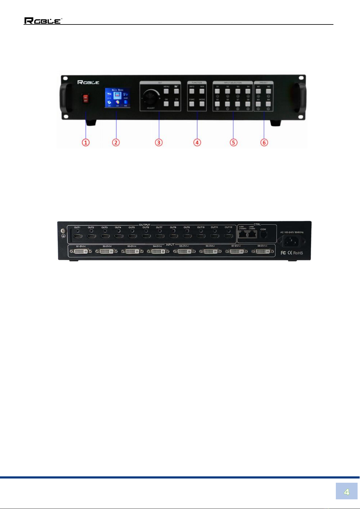
5.1 Front Panel...................................................................................................... 4
5.2 Rear Panel....................................................................................................... 4
6. Device Debugging................................................................................................. 4
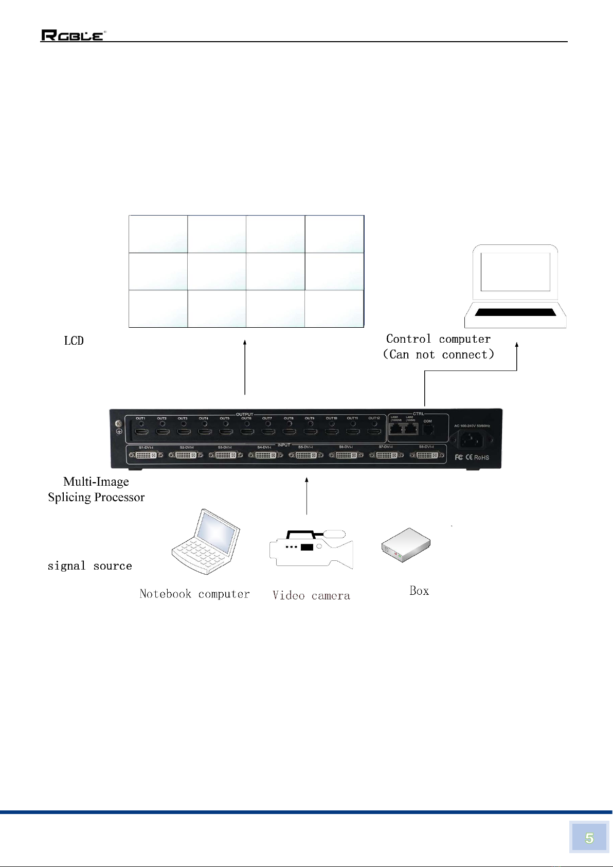
6.1 Device Connection........................................................................................... 4
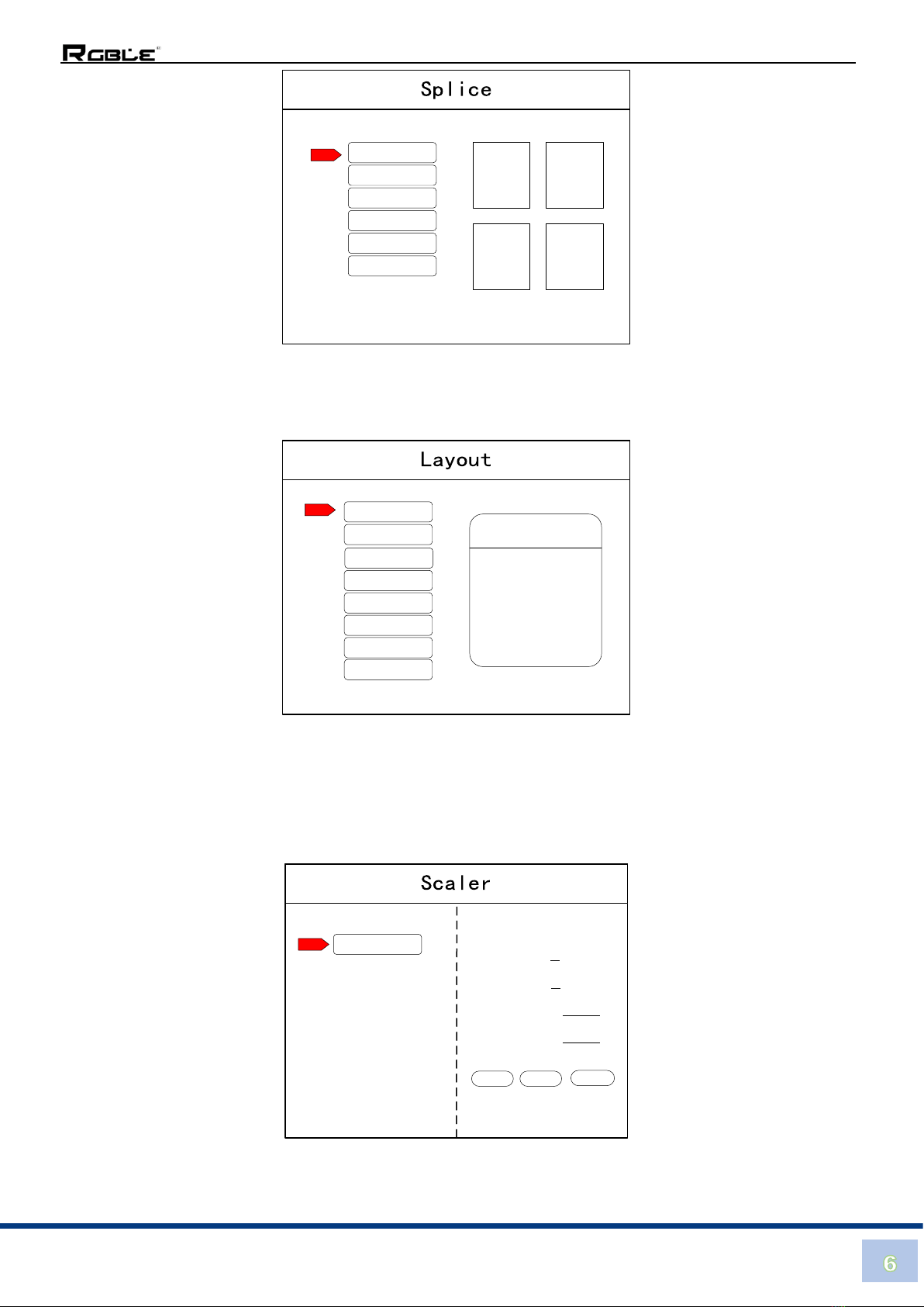
6.2 Debugging Steps.............................................................................................. 5
6.3 Case Study....................................................................................................... 8
6.4 Function key..................................................................................................... 9
6.5 Advanced Menu..............................................................................................11
7. Software Control...................................................................................................12

Stock Code 873117 en.rgble.com 400-1661-021
8 DVI-U inputs and 12 HDMI outputs
Video Wall Processor with Preview function
1. Introduction
The RGBLE VWP -812 video wall processor is a high-end video processing equipment
developed and manufactured by our company for LCD large screen display and so on. It has
adopted the CrossInt smart splicing technology specially designed for splicing display and all
display modules are locked by FST technology before synchronous output, eliminating the
asynchronous display between contents of multiple modules.
2. Features
⚫Supports 8 DVI-U inputs Compatible with DVI/HDMI/VGA/CVBS).
⚫Up to 8 layouts/windows in total
⚫Colorful LCD screen for the real-time information and menu setting
⚫Supports sources real-time preview function (with 1000M LAN port)
⚫All 60Hz image processing, achieving smooth and non-tearing images
⚫Support output port mapping, allowing blind wire connections
⚫Support black/blue screen while wrong sources output
⚫Support mode and source switching effects (CUT of FADE effects)
3. Package Contents
Item Name
QTY
Unit
Video Wall Processor
1
Unit
User Manual
1
Pcs
Power cord
1
Pcs

Stock Code 873117 en.rgble.com 400-1661-021
4. Specification
Brand Name
RGBLE
Model Number
VWP-812
Video Inputs
Type
Description
8 DVI-U
Support up to 1920×1200@60Hz, downward compatibility.
Support DVI/HDMI/VGA/CVBS with different connectors
Compatible with HDMI1.3 and lower version, EDID version 1.3
Video Outputs
Type
Description
12 HDMI
Resolutions: 1024×768@60Hz till 1920×1080@60Hz
Support 60Hz/50Hz/30Hz output frame rates
Function Description
Outputs
12 outputs support splicing mode of arbitrary form, such as:
3×4, 2×6 etc.
8
layouts/windows
Up to 8 windows or layouts in total
Each layout can be freely zoomed and adjusted. Images can
overlap each other.
1000M Preview
The signal image can be gained on computer at real time by
control software which includes both input signal and output
signal
Switching Effect
When switching signals or user-modes, users can set up
different effects and time
General
PC Control
RS232/RJ45 Ethernet
Weight
5.4kg
Operating
Temperature
0°C ~ 40°C / 32°F ~ 104°F
Storage
Temperature
-20°C ~ 60°C / -4°F ~ 140°F
Relative Humidity
20~90% RH (non-condensing)
Dimension
440x290x66mm
Input Power
AC 110-220V 50/60Hz
Warranty
1 years

Stock Code 873117 en.rgble.com 400-1661-021
5. Operation Controls and Functions
5.1 Front Panel
①POWER: Power switch ON/OFF
②Colorful LCD screen: for fast setting, information viewing
③SET: including ADJUST knob, OK, MENU, BACK and CONFIRM
④FUNCTION: Function key area which includes INFO, WIN, FUNC, MODE
⑤INPUT SELECTION: 8 signal sources fast switching buttons
⑥PRESET: User-Mode recall buttons
5.2 Rear panel
①INPUT: 8 DVI-I input ports (Compatible with DVI/HDMI/VGA/CVBS)
②OUTPUT: 12*HDMI output ports
③CTRL: Control port which contains LAN (100M), LAN (1000M), COM (serial port)
④POWER: Power supply port, AC 110-220V 50/60Hz
6. Device Debugging
6.1 Device Connection
Device connection could be divided into three parts: power connection, signal connection
and control connection (used for software debugging).
Power connection: device power supply. Connection method: connect power cord to
power plug.
Signal connection: the method transferring signal from signal source to LED large screen,
method: signal source (e.g.: computer) →Mosaic Processor →LCD.
Control connection: connect control computer with device control port and debug device
connection method. There are three connection methods
(1) Connect 100MB network control port with splicer LAN (100M) port, which can set device

Stock Code 873117 en.rgble.com 400-1661-021
software
(2) Connect computer gigabit network port with splicer LAN (1000M) port, which can not only
set device but also echo signal source image.
(3) Connect one crystal head of serial port line which is randomly donated by device with
splicer COM port, and plug DB9 into computer serial port. Any kind of method among the
three can realize device software control.
Connection diagram:
6.2 Debugging Steps
Step 1: Press “MENU” to enter into main menu interface and click “Splicing Mode” to select
splicing mode: 2×2、2×3、2×4、2×5、2×6、3×2、3×3、3×4、4×2、4×3、5×2、M×N.

Stock Code 873117 en.rgble.com 400-1661-021
Note: Select M * N to customize the stitching method
Step 2: To get back to main menu interface to select “Image layout” and enter into image
number selecting interface to select image number required to be set.
Note: This step can be skipped for signal image. For multi-image, it’s OK if image number
and item requirement are in consistent. Following operations can be taken to set when layout
is not in consistent.
Step 3: Press “OK” and return to main menu interface; select “Image parameter” and enter into
its setting interface to set size and position of each image.
Note: there are two ways for number input:
2×2
2×3
2×4
2×5
2×6
3×2
Num in box is PORT
OK 2 map INFO view
1 2
3 4
Layout 1
Layout 2
Layout 3
Layout 4
Layout 5
Layout 6
Layout 7
Layout 8
WIN1
S1
Window 1
Select window
Click OK to next
H POS:0
V POS:0
H SIZE:1920
V SIZE:1080
×1 ×10 ×100
Press FiNGER select

Stock Code 873117 en.rgble.com 400-1661-021
(1) Adjust by rotate knob. Step length can be adjusted by “×1” “×10”“×100”, for instance,
“×100”means that number of rotate knob increases by 100 each time.
(2) Input by number of the front panel. For example,
of the key refers to figure 1.
Step 4: Press “MENU” and return to main menu interface; select “Save setting” to enter into
Data storage interface; select any mode and click “OK” to save data.
Note: Mode 1 is default startup data of device boot; it’s suggested that the most common
mode or that required by device boot should be saved to Mode 1.
At this point, basic device debugging is completed. If there is other requirement, repeat the
operation and save it as other mode.
After device debugging, just recall saved data according to different condition requirements in
later stage.
Data recall is divided into forms:
(1) For Shortcut key call, only select and press the “M1-M4” buttons on the front panel which
is convenient when mode scenario is few.
(2) For users to recall from the Main Menu, press “MENU” and select “User Mode” to enter
into its extraction interface. Then select needed mode and click “OK”.
S1
Mode 1
Mode 2
Mode 3
Mode 4
Mode 5
Mode 6
Mode 7
Mode 8
WIN 1
S1
¼
MODE 1
SPLICE 2×3
LAYOUT
M1 M2 M4M3
Mode 1
Mode 2
Mode 3
Mode 4
Mode 5
Mode 6
Mode 7
Mode 8
WIN 1
S1
¼
MODE 1
SPLICE 2×3
LAYOUT

Stock Code 873117 en.rgble.com 400-1661-021
6.3 Case Study
Device debugging steps are explained by following cases.
Case: There are 12 LCD screens arranged in 3 rows and 4 columns, as shown in the
following figure:
Requirement: all LCD screens are spliced together as a whole one:
Arrangement of LCD screen
Display chart
Debugging Steps:
Step 1: Press “MENU” and enter into main menu interface to select “Cross Mosaic” of the first
item “Device mode”.
Step 2: Press “OK” to return to main menu interface; The large screen splicing is finished,
select signal source needed to display on screen and click corresponding key(s1-s8).
3×3
3×4
4×2
4×3
5×2
M×N
1 2 3
5 6 7
910 11
½4
8
12
Num in box is PORT
OK 2 map INFO view

Stock Code 873117 en.rgble.com 400-1661-021
Step 3: After normal display of large screen, save all setting data. Press “Save setting” to
enter into “Save setting” interface to select “Mode 1” and click “OK”. Things will be fine when it
suggests saving successfully.
Note: Mode 1 is default startup data of device boot; it’s suggested that the most common
mode should be saved to Mode 1 and the device can save 32 kinds of modes at most.
6.4 Function key:
Brief explanation of function key:
INFO: Information query key. Click this key and enter into its interface showing whether all
signal sources are inputting normally. Its interface is shown as below. Red light means signal
is lost while green one shows signal is normal.
WIN: Image key. Click this key to enter into its interface and signal source selection can be
made in following interface.
Mode 1
Mode 2
Mode 3
Mode 4
Mode 5
Mode 6
Mode 7
Mode 8
WIN 1
S1
¼
MODE 1
SPLICE 2×3
LAYOUT
S1 S2
S3 S4

Stock Code 873117 en.rgble.com 400-1661-021
MODE: Mode recall key…Press this button to enter the user mode interface, and users can
recall the saved modes
FUNC: Function key. Press this key to enter into its interface which includes: brightness
adjustment, special effect switch, VGA adjustment, image matting setting, edge feather,
transparency setting, intelligent warm backup, preview monitor, IP setting, serial port,
freeze frame, local and global, color space, input brightness and switch time. The following
are explanations of those common functions.
1). Brightness adjustment
The device supports 1-255 stairs brightness adjustment. Brightness of all screen body
can be adjusted synchronously to meet customers’ different brightness adjustment
requirements for different conditions.
2). Output condition
Use this button to set black screen or blue screen, and then you can switch the output state.
3). Special effect switch
The device supports directly switching the fade-in and fade-out effect, and ensures that
the switching process is without flower screen, flash screen or black screen.
4). Special effect time
Set image switch times or switch time among different modes with the range of 0.2s-3s.
5). VGA adjustment
Since VGA signal belongs to analogue one, it tends to causes deviations among
common functions. The product has two kinds of VGA corrections which are automatic
correction and manual correction.
6). IP setting
WIN 1
S1
WIN2
S1
Mode 1
Mode 2
Mode 3
Mode 4
Mode 5
Mode 6
Mode 7
Mode 8
WIN 1
S1
¼
MODE 1
SPLICE 2×3
LAYOUT

Stock Code 873117 en.rgble.com 400-1661-021
Set device IP address for software debugging.
7). Clipped view
Specifies that the full screen of the signal source is placed on the screen in a particular
area. You can set the specified location and size of the signal source. The value "0" represents
no clipped view.
8). Local and global
Switch local display or global display of certain image on the condition that data of local
display is already set.
9). Freeze frame
Set stillness or movement of certain image which is often used for field change or
background switch.
10). Freeze full screen view
Set all images immobile or mobile.
11). Serial port setting
Set device serial port like baud rate and etc.
12. Output mapping
Set splicing mode and output port mapping.
6.5 Advanced Menu
Language setting
Set device language: English or Chinese
Output resolution
Support single output resolution, user-defined resolution is available and support 30HZ,
50HZ and 60HZ frame rate. Device default output resolution is 1920×1080@60HZ.
Factory setting
All data are cleared and the device returns to default state.
Common functions
Click “FUNC” to get quick access to common setting function.
Keyboard lock
Lock front panel key to avoid misoperation of irrelevant personnel.
Technical Support
Inquire device version number and its IP address.
Window 1
Select window
Click OK to next
H POS:0
V POS:0
H SIZE:1920
V SIZE:1080
×1 ×10 ×100
Press FiNGER select

Stock Code 873117 en.rgble.com 400-1661-021
7. Software Control
Step 1: Please obtain the control software provided by RGBLE
Step 2: Extract the rar. File and install the control software on the control PC
Step 3: After install, double click to run the software.
The default User name is: administrator, no password, click “ok” to login and it will show below
interface:
Before getting started, please make sure the control PC and controller is connected either by
LAN or RS232 cable: If using the LAN control, the default IP address of the controller is
192.168.0.100, please also make sure the control PC and controller is at the same gateway. For
using the RS232, please check and confirm which COM port is available on the PC.

Stock Code 873117 en.rgble.com 400-1661-021
Below will be showing on using the IP control.
3 steps to get connected: Click “Connect”, Type the IP address 192.168.0.100, then click “OK”
After well connected, it will pop-up a window for synchronization with the control software, click
to “OK” to sync.
After click “OK” to sync, it will jump to “Switching” interface:

Stock Code 873117 en.rgble.com 400-1661-021
“Switching” interface, there are several sections:
1: For the switching effects and time setting: Fade or Cut
2: 8 Signals type DVI/VGA/CVBS
3: Window position lock button
4: Display the details of the User Modes or the Signal sources
5: Collapse for the User Mode or the Signal Source
6: Video Wall Operation area
7: For the local sources preview (only with 1000M LAN port can support)
“Device” Interface:
After click “Device”, it will be showing as below: For this model, we only use the “Connect/
disconnect” and “Exit” two buttons, the rest are for other equipment.

Stock Code 873117 en.rgble.com 400-1661-021
“Setting” Interface:
Users can set the video wall configuration accordingly. Open new window, save or recall user’s
mode, and default back to factory mode and so on function here.
Screen config and Output Map:
Screen config (for the Video wall number and resolution settings):

Stock Code 873117 en.rgble.com 400-1661-021
Output Map (for adjusting the output ports to match with the displays):
Drag the OUT1...OUT12 up to the Port1...Port12 to replace and adjust

Stock Code 873117 en.rgble.com 400-1661-021
2: Open Win, User-mode, Save-Mode, Factory Default, Echo on/off
Open Win: to open a new window on the Video Wall
For open a window, it also can be done by pressing and holding left click of the mouse to drag
and release on the video wall operation area, and users can adjust the window size by moving
to the edge of the window:

Stock Code 873117 en.rgble.com 400-1661-021
User-Mode: For recalling the saved user mode(presets), total can save 32 presets
Save-Mode: For save the current settings as a user-mode/preset
Factory default: Click this one will reset all the parameters as factory default mode

Stock Code 873117 en.rgble.com 400-1661-021
Echo On: Turn on the local preview function on the control PC (only support with 1000M Port)
Echo Off: Turn off the local preview function on the control PC (only support with 1000M Port)
Screen Control: those functions are not available for this mode
Table of contents
Other RGBLE Media Converter manuals