RGBLE DLU-H 4K User manual

Stock Code 873117 en.rgble.com 400-1661-021
P/N: P01002
4K AV over IP with
Video Wall Processing
DLU-H (4K)
User Manual
VER 1.0

Stock Code 873117 en.rgble.com 400-1661-021
P/N: P01002
Thank you for purchasing RGBLE product
For optimum performance and safety, please read these instructions carefully before
connecting, operating or adjusting this product. Please keep this manual for future reference.
Surge protection device recommended
This product contains sensitive electrical components that may be damaged by electrical
spikes, surges, electric shock, lighting strikes, etc. Use of surge protection systems is highly
recommended in order to protect and extend the life of your equipment.
Table of Contents
1. Introduction......................................................................................................2
2. Features...........................................................................................................2
3. Package Contents............................................................................................2
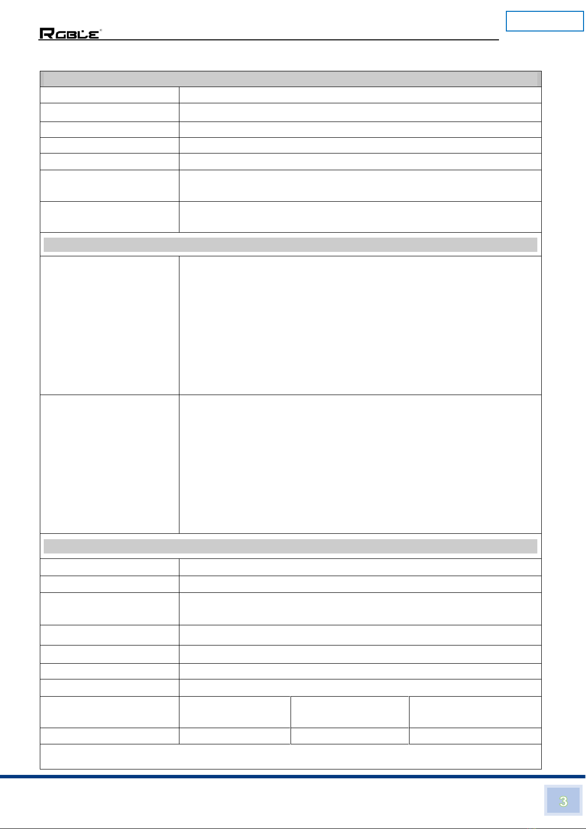
4. Specifications...................................................................................................3
5. Operation Controls and Functions...................................................................4
5.1. Encoder Panel.........................................................................................4
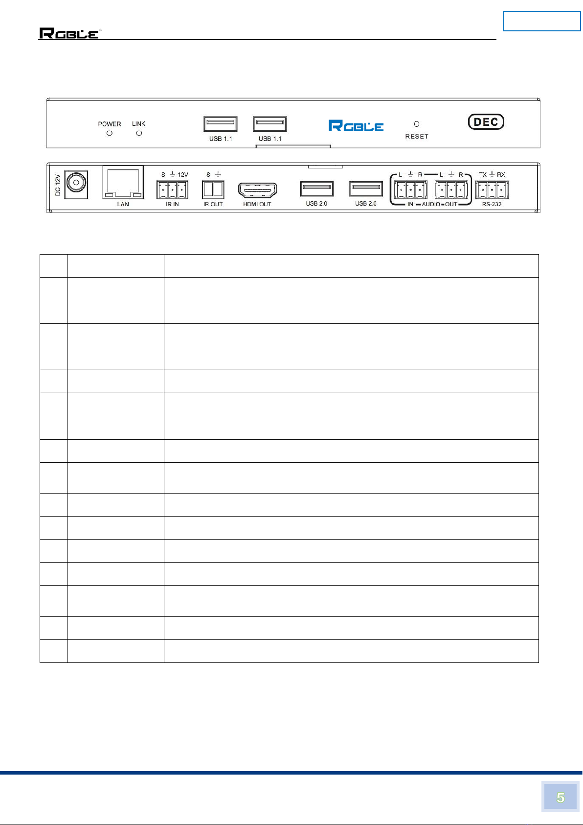
5.2. Decoder Panel.........................................................................................5
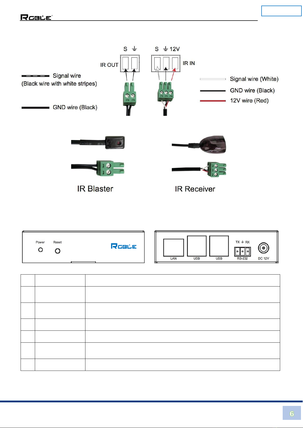
5.3 IR Pin Definition.......................................................................................6
6. Controller Box...................................................................................................6
7. Controller Specifications...................................................................................7
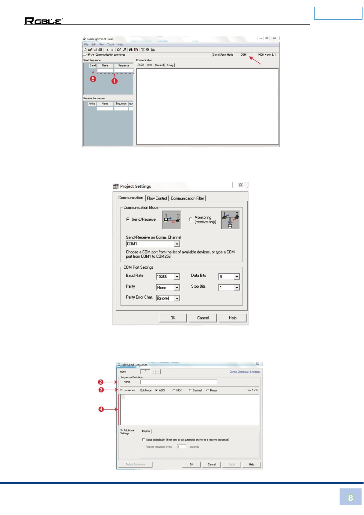
8. ASCII Control.................................................................................................7
9. Web GUI User Guide......................................................................................10
10. Play Video Stream on PC...............................................................................26
10.1 Connecting Web for Control..................................................................26
10.2 VLC Media Player Instruction................................................................29
11. Connection Diagram.......................................................................................32
12. Switch Mode...................................................................................................32

Stock Code 873117 en.rgble.com 400-1661-021
P/N: P01002
4K AV over IP with Video Wall Processing
1. Introduction
The RGBLE DLU-H (4K) AV over IP with Video Wall Processing adopts JPEG2000 solution and
supports USB2.0 KVM function. It supports up to 4K60 4:4:4 input, 4K60 4:2:0 output. Encoder
supports 4K60 4:4:4 HDMI loop output and H.264/H.265 coding auxiliary stream (for image
echo). It can realize multi-channel digital audio and analog audio transmission. It supports 1G
Ethernet, bidirectional RS-232, two-way IR control and POC function.
2. Features
1) HDMI 2.0b, HDCP 2.2 compliant
2) Support 18Gbps video bandwidth
3) Support up to 4K60 4:4:4 input, 4K60 4:2:0 output
4) Color space: RGB, YCbCr 4:4:4, YCbCr 4:2:2
5) JPEG2000 main stream and standard H.265 codec auxiliary stream
6) Transmit video, audio, infrared, USB2.0 KVM over Ethernet
7) Support unicast, multicast, matrix and video wall function
8) Support 1G Ethernet switch, router and hub device transmission
9) Flexible control by Web UI, IOS tablet and the third-party controller
10) HDMI audio formats: LPCM, Dolby Digital/Plus/EX, Dolby True HD, DTS,
DTS-EX, DTS-96/24, DTS High Res, DTS-HD Master Audio, DSD
11) Smart networking design for easy and flexible installation.
3. Package Contents
Qty
Item
1
4K AV over IP Encoder
1
4K AV over IP Decoder
2
12V/1A Power adapter
1
User Manual
2
12V IR Receiver cable
2
5V IR Blaster cable
2
2-pin 3.81mm phoenix connector
8
3-pin 3.81mm phoenix connector

Stock Code 873117 en.rgble.com 400-1661-021
P/N: P01002
4. Specifications
Technical
HDCP Compliant
HDCP 2.2 and HDCP 1.4
Video Bandwidth
18Gbps
Video Resolution
480i ~1080p50/60Hz, 4Kx2K@24/30Hz, support 4k2k@60Hz input
Color Space
RGB, YCbCr4:4:4, YCbCr4:2:2, YCbCr 4:2:0
Color Depth
8/10/12-bit (1080P60Hz) 8-bit (4K60Hz)
HDMI Audio Formats
LPCM 2/5.1/7.1CH, Dolby Digital, DTS 5.1, Dolby Digital+, Dolby
TrueHD, DTS-HD Master Audio, Dolby Atmos, DTS:X
ESD Protection
Human-body Model:
±8kV (Air-gap discharge), ±4kV (Contact discharge)
Connection
Encoder
Input:1×HDMI Type A [19-pin male]
1x L/R Audio IN [3.81mm Phoenix connector]
1x IR IN [3.81mm Phoenix connector]
Output: 1×HDMI Type A [19-pin male]
1x L/R Audio OUT [3.81mm Phoenix connector]
1x IR OUT [3.81mm Phoenix connector]
Control:1x RS-232 [3.81mm Phoenix connector]
1×LAN [RJ45 jack]
1×USB [USB Type B]
Decoder
Input:1x IR IN [3.81mm Phoenix connector]
1x L/R Audio IN [3.81mm Phoenix connector]
Output:1×HDMI Type A [19-pin male]
1x IR OUT [3.81mm Phoenix connector]
1x L/R Audio OUT [3.81mm Phoenix connector]
Control:1×LAN [RJ45 jack]
2×USB1.1 [USB-A male]
2×USB2.0 [USB-A male]
1x RS-232 [3.81mm Phoenix connector]
General
Housing / Color
Metal Enclosure / Black
Dimensions / Weight
200(W)×100 (D)×20mm (H) / 500g*2
Power Supply
Input: AC100~240V 50/60Hz
Output: DC12V/1A (US/EU standard, CE/FCC/3Ccertified)
Power Consumption
TX: 9.8W, RX: 7W
Operating Temperature
0°C ~ 45°C / 14°F ~ 104°F
Storage Temperature
-20°C ~ 60°C / -4°F ~ 140°F
Relative Humidity
20~90% RH (non-condensing)
Resolution/
Cable Length
4K60–Feet Meters
4K30–Feet/Meters
1080P60–Feet/Meters
HDMI IN / OUT
16ft / 5M
32ft / 10M
50ft / 15M
The use of “Premium High-Speed HDMI” cable is highly recommended.

Stock Code 873117 en.rgble.com 400-1661-021
P/N: P01002
5. Operation Controls and Functions
5.1 Encoder Panel
5.2
5.3
5.4
Name
Function Description
1
Power LED
When the power is connected normally,
Red LED flashes: the system is booting
Red LED illuminates: booting successfully
2
LINK LED
When the system starts up normally,
Green LED flashes: no signal
Green LED illuminates: signal input
3
RESET button
Power on the device while pressing this button, when POWER LED
and LINK LED flash simultaneously, release the button to reset the
device to factory settings.
4
DC 12V
DC 12V power input interface.
5
LAN
1G LAN port, which can be connected to a third-party network switch
to form a distributed system.
6
IR IN
IR signal input interface.
7
IR OUT
IR signal output interface.
8
RS-232
Bidirectional serial signal interface.
9
USB HOST
USB-B connector for connecting a PC as KVM function.
10
AUDIO IN
3-pin phoenix connector for analog audio input, which can be
embedded in the HDMI stream or directly transmitted.
11
AUDIO OUT
3-pin phoenix connector for analog audio output.
12
HDMI OUT
HDMI loop out for display.
13
HDMI IN
HDMI source input.
14
RS-232+Update
Dip Switch
RS-232: the RS-232 port is used for serial port passthrough.
Update: the RS-232 port is used for MCU update.

Stock Code 873117 en.rgble.com 400-1661-021
P/N: P01002
5.2 Decoder Panel
Name
Function Description
1
Power LED
When the power is connected normally,
Red LED flashes: the system is booting
Red LED illuminates: booting successfully
2
LINK LED
When the system starts up normally,
Green LED flashes: no signal
Green LED illuminates: signal input
3
USB1.1 x 2
USB1.1 device interface.
4
RESET button
Power on the device while pressing this button, when POWER LED
and LINK LED flash simultaneously, release the button to reset the
device to factory settings.
5
DC 12V
DC 12V power input interface.
6
LAN
1G LAN port, which can be connected to a third-party network switch
to form a distributed system.
7
IR IN
IR signal input interface.
8
IR OUT
IR signal output interface.
9
RS-232
Bidirectional serial signal interface.
10
USB2.0 x 2
USB2.0 device interface.
11
AUDIO IN
3-pin phoenix connector for analog audio input, which can be
embedded in the HDMI stream or directly transmitted.
12
AUDIO OUT
3-pin phoenix connector for analog audio output.
13
HDMI OUT
HDMI output port.

Stock Code 873117 en.rgble.com 400-1661-021
P/N: P01002
5.3 IR Pin Definition
IR Blaster and IR Receiver wire’s definition as below:
6. Controller Box
Name
Function Description
1
Power LED
Power LED indicator.
When the unit is powered on, the white LED will be on.
2
Reset button
Long press the button for 6 seconds to reset the controller to factory
default mode. IP address will be reset to static 169.254.23.100.
3
LAN port
Connect to the switch with an UTP cable.
4
USB ports
Reserved ports.
5
DC 12V
Plug the 12V/1A DC power cord into this port and connect the power
adapter to an AC outlet.
6
RS-232
3-pin Phoenix connector for RS-232 command transmission.
Note: The control system can use the RS-232 or LAN port to control video over IP products,
please contact your supplier for detail API doc

Stock Code 873117 en.rgble.com 400-1661-021
P/N: P01002
7. Controller Specifications
Technical
1
Control ports
1×RS-232 [Phoenix connector]
1×LAN [RJ45 jack]
4×USB [Type A, reserved port]
2
ESD Protection
Human-body Model:
±8kV (Air-gap discharge), ±4kV (Contact discharge)
3
Housing
Metal enclosure
4
Color
Black
5
Dimensions
30(W)×100(D)×26(H)
6
Weight
371g
7
Power Supply
Input: AC100~240V 50/60Hz
Output: DC12V/1A (US/EU standards, CE/FCC/3C certified)
8
Power Consumption
4W
9
Operating Temperature
0°C ~ 40°C / 32°F ~ 104°F
10
Storage Temperature
-20°C ~ 60°C / -4°F ~ 140°F
11
Relative Humidity
20~90% RH (non-condensing)
8. ASCII Control
The Controller supports ASCII control. There are two ways to send ASCII control command.
The first way: Connect the Controller with PC via the RS-232 phoenix connector on the
Controller, and then use a Serial Command tool on PC to send command. The specific
operation is as follows:
Step 1: Connect the Controller with PC via the RS-232 phoenix connector on the Controller, as
shown in the following connection diagram.
Step 2: Open a Serial Command tool on PC such as “Docklight” (The shortcut icon is shown
below).

Stock Code 873117 en.rgble.com 400-1661-021
P/N: P01002
You will see the following page.
Step 3: Click the “COM1” tab, there will be a “Project Settings” page. Choose the COM port to
connect the software, set the Baud Rate, Data Bits, Parity, Stop Bits and then click the “OK”
button, as shown in the following page.
Step 4: Double click the “label 1” blank area. You will see the following page. At “label 2”, you
can explain sequence definition. At “label 3”, you need to choose the sequence mode. At “label
4”, you can input the ASCII command of the product. Then click the “OK” button.

Stock Code 873117 en.rgble.com 400-1661-021
P/N: P01002
Step 5: Click the “Send” button at “label 5” to send the command.
The second way: Connect the Controller with PC via the LAN port on the Controller, and then
use a TCP Command tool on PC to send command. The specific operation is as follows:
Step 1: Connect the Controller with PC via the LAN port on the Controller, as shown in the
following connection diagram.
Step 2: Open a TCP Command tool on PC such as “Hercules”. You will see the following page.
Step 3: Input the IP Address (169.254.23.100) and Port number (6008) of the Controller box at
“label 1”, and then click the “Connect” button. PC will try to connect the Controller as shown in
“label 2”.
Step 4: After successful connection, input commands at “label 3”, then click the “Send” button to
send commands.
Please contact to our sales agent about API command list of the product.

Stock Code 873117 en.rgble.com 400-1661-021
P/N: P01002
9. Web GUI User Guide
You can use Controller’s Web GUI to control all products through the Switch. Firstly, you have
to know Controller’s current IP address. Please refer to the operation of “8. ASCII Control”, input
the command “server load” in “Docklight” or other Serial Command tool on PC, then you will get
the command feedback as follows:
As shown in the above figure, the Controller’s current IP address is 169.254.23.100.
Secondly, you need to change the PC’s IP Address. The operation method is shown as below:
Step 1: The LAN port of the Controller is directly connected to a Switch, the PC and other IP
products you need to control are also connected to the Switch. The connection diagram is
shown as below.

Stock Code 873117 en.rgble.com 400-1661-021
P/N: P01002
Step 2: On the PC, go to Control Panel > Network and Internet > Network Connections >
Local Area Connection, right click on it, choose Properties.
Double click “Internet Protocol Version 4 (TCP/IPv4)”.

Stock Code 873117 en.rgble.com 400-1661-021
P/N: P01002
Choose “Use the following IP address”. For instance, input 169.254.23.30 as your PC’s IP
address, 255.255.255.0 as Subnet mask, and then click on “OK” again.
Notice: The IP address of the PC, Controller and other IP products should be in the same
network segment. As the Controller’s IP address is 169.254.23.100, the computer's IP should
be set 169.254.23.X (X contains 1~255 except 100).
Step 3: Input the Controller’s IP address into your browser on the PC to enter the Web GUI
page.
After entering the Web GUI page, there will be a Login page. Please enter the default User and
Password “admin” to login.
Then, select the product “4K60 over IP JPEG2K (1G switch)”.
Finally, click the “Sign In” button to enter Web GUI function pages.
Notice: When you select a type of product on the Login page, you can only connect the type of
products to the switch.

Stock Code 873117 en.rgble.com 400-1661-021
P/N: P01002
The Web GUI pages are shown as below:
Devices Page
You need to click the “Search” button to search all products you have connected.
Encoders are shown in green on the top area and Decoders are shown in blue on the below
area. Every small interface on Encoder or Decoder area shows the product’s name, IP address
and software version.
You can obtain detail information about the encoder or decoder when you click the lower right
corner of each small encoder or decoder interface.

Stock Code 873117 en.rgble.com 400-1661-021
P/N: P01002
Encoder Attribute
The above figure displays some basic information about the Encoder, such as Mac address,
software version, video resolution and HDCP version. The alias name can be modified as
required.
1) Audio Input
You can choose the audio source of the video. “HDMI” means that the decoder audio follows
input source, “Analog L/R” means that the decoder audio follows external audio input (AUDIO
IN).
2) IP Setting
You can set the device’s IP Address, turn on/off DHCP, or just click the “Apply” button to
perform “Reset Device to Factory”, “Reboot device” and “Show Me”. After all the settings are
completed, you can click the “Save” button to save

Stock Code 873117 en.rgble.com 400-1661-021
P/N: P01002
Decoder Attribute
Decoder basically has the same properties as the Encoder, except for “Set Output Video
Format”.
In the drop-down menu of “Set Output Video Format”:
Auto: It means that the decoder will adapt and output the best resolution according to the EDID
of the display device.
Same as Input: It means that the resolution of the signal output from the decoder is the same
as that of the signal input from the encoder. The rest is to set fixed output resolution, such as
4K30-> 720P60Hz.
After all the settings are completed, click the “Save” button to save.
The rest is set to output a fixed resolution, such as 4K30-->720P60Hz.
After all the settings are completed, you can click the “Save” button to save.

Stock Code 873117 en.rgble.com 400-1661-021
P/N: P01002
Zones Page
Click the “+” icon to create new zones, and you can create no more than 16 zones. Each zone
can set different application methods (matrix / video wall).
Click the icons above to edit the zone name or delete the selected zone.
Click the “+” icon to add Decoders for the zone, as shown in the figure below. After being
selected, the Decoder will be in the corresponding zone.

Stock Code 873117 en.rgble.com 400-1661-021
P/N: P01002
There are three “preset” in Zones, each preset can set Matrix, Videowall and Multiview.
■ Zones Matrix Editing
Click the “+” icon to build new correspondence. Drag a Decoder to the corresponding frame,
then drag the required Encoder to the same frame, as shown in the following figure.

Stock Code 873117 en.rgble.com 400-1661-021
P/N: P01002
You can also drag Encoder into the frame of ALL RX, so that you can match an Encoder video
signal to ALL Decoders, as shown in the following figure:
■ Video Wall Configuration
You can set the wall’s name, rows, columns and Bezel adjustments. After completing the
settings, click “Save” to save the configuration, or click “Delete” to delete.

Stock Code 873117 en.rgble.com 400-1661-021
P/N: P01002
Then drag Decoders to the wall frames, and drag the signal sources in Encoders to the frame of
Encoder, as shown in the following figure:
A 2 * 2 video wall setting is composed, and a maximum wall of 4 * 6 can also be set. If you need
to delete this wall, just click the “Delete” button.
EDID Page
You can set the EDID of each Encoder, as shown in the following figure:
Table of contents