manuals.online logo
Brands
  1. Home
  2. •
  3. Brands
  4. •
  5. RGBlink
  6. •
  7. DVD Player
  8. •
  9. RGBlink vsp 618 User manual

RGBlink vsp 618 User manual

–
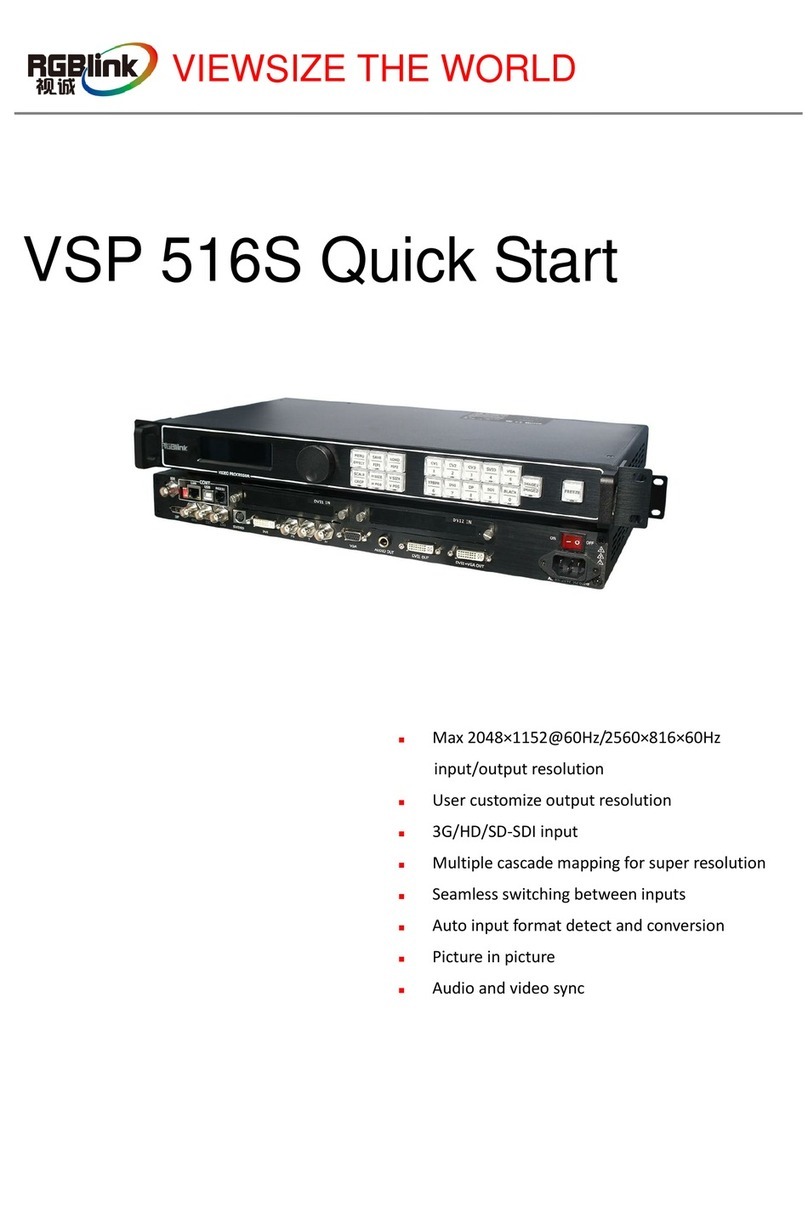
Installation and cabling features
Connections
LAN RJ-45 port
2
3
4
USB control port
5HDMI Input Connectors
14
DVI Output Connector
27 Power Switch Button
28 Power Cord Connector IEC-3
Step 1-Mounting
Turn off or disconnect all equipment power sources.
Step 5- Composite Input
Used to input composite signal
(PAL, NTSC, SECAM compatible).
IMPORTANT
Refertowww.rgblink.comfor
thecompleteusermanual and
installationinstructionsbefore
connectingtheproducttothe
powersource.
1Mini Switches
RS232 control port
Composite Female BNC connectors
17
~
DVI (DVI-I) Input Connector
DSUB 15-pin VGA Input Connector
26 DSUB 15-pin VGA Output Connector
18
19
20
23
24
25
15
Component Female BNC Connector
SDI Female BNC connector
S-Video (DIN 4) Input connector
Step 3-SDI Input
Used to connect the video sources from HDD Media
Player, HD Camera. ( SDI Inputs are optional
modules, for VSP 618 with SDI inputs model are
VSP 618B, VSP 618BC or VSP 618BCD.)
VIEWSIZE THE WORLD
NOTE For full installation, configuration, and operation details, refer to the
VSP 618 user manual, which is available at www.rgblink.com.
This guide provides quick start instructions for an experienced installer
to set up and operate the VSP 618.
10 11
13
6
7~9
12 TX Card Power Connector
TX Card DVI Input Connector
22
~
HDMI Ouput Connector
Step 2-HDMI Input
Used to connect the video sources from HDD
Media player, DVD Player, Computer. (HDMI
Inputs are optional modules, for VSP 618 to
support HDMI inputs model are VSP 618C, VSP
618BC or VSP 618BCD.)
Step 7-DVI input
Input the signal from computer,
DVI signal generator and so on.
Step 8-Component input
Used to input signal from Players
like DVD; Input signal as R/Pr G/Y B/Pb
from left.
Step 4-SDI Loop out
SDI loop out connector is used to connect another
VSP 618B or other SDI-based equipment.
Step 6-S-Video input
Used to input S-Video signal
(PAL, NTSC, SECAM compatible).
Step 9-VGA input
Input from computer or VGA source.
Step 10-HDMI output
Used to connect HDMI-based monitor or
LED Display Control system which has
HDMI interface.
Connect to the monitor or LED control
system which has DVI interface.
Step 11-DVI output
Step 12-VGA output
Connect to the monitor, projector and so on.
VSP 618 Quick Start
Rev 1.0
Page 1 of 3
Address:S603-604 Weiye Building Torch Hi-Tech Industrial Development Zone Xiamen,Fujian Province, P.R.C
Tel: 00865925771197 Fax:00865925771202
Email: [email protected] http://www.rgblink.com
NOTE
Push [I/II] button to go to dual channels mode (PIP,
picture in picture), select window 1 from CV1,
CV2,CV3,SVID,YCbCr,SDI1,SDI2, and window 2
from VGA,YPbPr,DVI,HDMI1and HDMI2.
Push [AB] button to make fade in and fade out
function. Window 1 is default small window image,
window 2 is the Bottom large image. Window 1 is
default selected input source ready for scale operation,
if user wants to scale the bottom image, need to push
to switch to the input button first and then push scale
button to do the scaling for the image.
Step18- Power
Plug in power cord which has IEC connector, VSP 618
support AC power from 85 to 260 VAC,50-60Hz, which
means world wide compatible.
Step 13-LAN(Ethernet) port
Use twist CAT5 cable to connect to LAN port, user can
control VSP 618 based on default IP address:
192.168.0.100. User can also change the IP address by
RS 232 or USB.Twist CAT5 should be one end in
T568A, and anotherend in T568B standard.
LAN(Ethernet) port is not for standard configuration.
Step 1-Input Switch
Pin End 1
Wire Color End 2
Wire color
1White-green White-Orange
2Green Orange
3White-Orange White-green
4Blue Blue
5WhiteBlue White-blue
6Orange Green
7White-Orange White-brown
8Orange Brown
Crossover Cable CAT5 is
wired as
T568A at
one end and
T568B at the
other(Tx and
Rx pairs
reversed) is
crossover.
T568A T568B
RJ-45
Connector
Pins
Step 15-Serial port
Use RS232 to RJ11 cable to connect a control system or
computer to the back panel RJ11 port and the other end
on RS232 port. RS232 to RJ11 cable as following
definition.
RS-232 Funtion
2TX Transmit
3RX Receive
5GND Signal Ground
7--- Not used
8--- Not used
Pin RS-422 Funtion
TX- Transmit(-)
RX- Receive(-)
GND Signal Ground
RX+ Receive(+)
TX+ Transmit(+)
Insert Twisted
Pair Wires
RS232/RS422
Connector
Insert Twisted
Pair Wires
RJ11 Connector
RJ-11 Funtion
1
TX Transmit
2RX Receive
3GND Signal Ground4
--- Not used
Pin
Local control -- Front Panel Operation
VSP 618 supports twelve inputs: CV1, CV2,CV3,
SVideo,YCbCr,VGA,YPbPr,DVI,SDI1,SDI2,HDMI1,
HDMI2 (SDI1 and SDI 2 are only for VSP 618B,
HDMI and HDMI2 are only for VSP 618C ). push
each source button, will switch to each source input,
and display on the target monitor or display system.
NOTE
When there is not video or graphic input, and
user switch to that input, the last frame image
of the last input will keep on display.
Step 2-Scale
Push Scale button and go into scale setting menu. Use
UPor DOWN to go to Horizontal size, Vertical size,
Horizontal position, Vertical position setting page, and
push SEL to decide to set, and use UP or DOWN to
change the size or position value. Push SEL to send and
exit from the setting.
NOTE Keep pushing UP or DOWN button, the value
of the size or position will change faster and
Faster during setting values.
Rate of change will be from 1 to 10 and to 100.
Step 14-USB port
Use USB cable to connect the VSP 618 and
computer.
Powering Up
Push power button switcher to ON position. LCD
module on the front panel will show RGBLINK and
VSP 618 model information, and go into self
verification before it load the last setting configuration
data and send the processed image to the target display
or device. For the first time running, CV1 input is the
default input source. User can operate with VSP618
with local front panel and remote control with the
software run on the PC, remote control by RS232, USB
or TCP/IP.
Step 3-Output resolution
Push OUT button and use UP or DOWN button to go to
the right resolution for the monitor or display system,
andpush SEL button to decide to go to the resolution.
VSP 618 supports 21 output formats:
640×480×60Hz;800×600×60Hz;1024×768×60Hz
1024×768×75Hz;1280×720×60Hz;1280×768×60Hz;
1280×960×60Hz;1280×1024×60Hz;1360×768×60Hz;
1365×768×60Hz;1366×768×60Hz;1440×900×60Hz;
1400×1050×60Hz;1600×1200×60Hz;1680×1050×60Hz;
1920×1080×60Hz;1920×1200×60Hz;2048×1152×60Hz;
2048×1536×60Hz;1280×720×50Hz;1920×1080×50Hz;
Output resolution should be the same or large than the
monitor or display system resolution.
More resolutions can be accessed from PC.
NOTE
Step 4-Set Fade in and Fade out effect
Push [I/II] again will go back to single channel;
Check on the front panel, if two buttons lights
up, means work in PIP, else in single channel.
VSP 618 Quick Start
Rev 1.0
Page 2 of 3
Address:S603-604 Weiye Building Torch Hi-Tech Industrial Development Zone Xiamen,Fujian Province, P.R.C
Tel: 00865925771197 Fax:00865925771202
Email: [email protected] http://www.rgblink.com
Remote control -- Software Operation
NOTE For setup
software,
please check with
user manual. And
install correct
language version to
work with right
language user
interface.
Step 2-Output resolution
Select output resolution from pull down output list.
Step 3-Scale
User can scale the image with mouse drap and drop
operation; User can also scale by input the data into the
scale parameters and set.
Step 5-Save
Push “Save to flash”button and
select one of user mode to save, there
are three user mode in the list.
Save to flash
button, use to
save user mode
Step 5-Save
VSP 618 support 2 user saving mode. Push SAVE button
and SVAE1, SVAE2 buttons will light on, push any one of
them to save the setting. After that user can push each of
them to call the setting.
NOTE
SAVE1 setting is default user setting after VSP 618
power on.
All the user settings will gone after factory reset.
Step 4-Set up picture display mode
Under dual channels mode, user can set up
the pictures’s size and position,
as following:
Push this button to
show PIP
CV1,CV2,CV3,SVID,YCbCr,SDI1 or SDI2 is default
small picture, DVI,YPbPr,VGA,HDMI1or HDMI2 is
default bigger picture.
NOTE
Push this button to
show PBP.
Click “Subtitle on/off”button to insert
the subtitle,and click the
“transparent background”if user likes.
Input words (such as ad words) into the subsitle
dialog, which could contain up to 80 characters.
After finish click "Settings" button, subtitles will be
immediately displayed over the image.
Through the "Subtitle rolling" menu,
rolling or stationary subtitles can be
set. Currently, the VSP 618 only
supports lateral rolling. The Vertical
rolling is not supported yet.
Insert subtitle
Subtitle switch
Dragging the scrollbar to change the background
Color of words or subtitle background, you can click
the button to select the desired color.
Color of words or subtitle background
Subtitle running
Rolling speed of subtitle
Change the rolling speed
by draging the scrollbar.
Position of subtitle
Add LOGO
Download LOGO
Adjusting the horizontal
and vertical coordinates
can change the position
of subtitles on the screen. Width means the vertical
distance of the subtitle display area. When you have
set the subtitle position, subtitles will be displayed
within the set area.
Users can put any LOGO onto the big screen.
Users can choose whether or not
to show LOGO through button
" LOGO On/Off".
When turning on the button
"LOGO background color On/Off",
LOGO will be floating on the big screen with black
background.
When turning on the button "transparent LOGO
On/Off", LOGO will be transparent over big screen.
Use the RS 232 port on the computer, baudrate should be
115200.
Step 1-Set up communication
Set COM Open COM Close COM
The LOGO picture should be revised to specified
format and size. The user can download LOGO to
the device through "download logo" menu. Turn on
the button "Logo on/off", the logo will be displayed
to the big screen. Adjusting the horizontal (X) and
vertical coordinates (Y) can change the position of
LOGO on the screen.
Insert subtitle and LOGO
“Setting subtitle” in the menu “Video Processor”
provides function for inserting the subtitle and logo .
VSP 618 Quick Start
Rev 1.0
Page 1 of 3
Address:S603-604 Weiye Building Torch Hi-Tech Industrial Development Zone Xiamen,Fujian Province, P.R.C
Tel: 00865925771197 Fax:00865925771202
Email: [email protected] http://www.rgblink.com

Other RGBlink DVD Player manuals

RGBlink venus x2 User manual

RGBlink

RGBlink venus x2 User manual

RGBlink VENUS X3 User manual

RGBlink

RGBlink VENUS X3 User manual

RGBlink VENUS X1PRO User manual

RGBlink

RGBlink VENUS X1PRO User manual

RGBlink VSP 516S User manual

RGBlink

RGBlink VSP 516S User manual

RGBlink venus x2 User manual

RGBlink

RGBlink venus x2 User manual

RGBlink VSP 516S User manual

RGBlink

RGBlink VSP 516S User manual

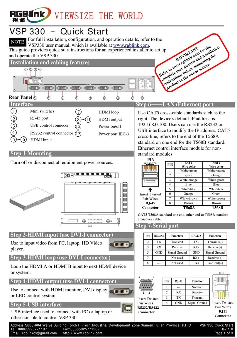
RGBlink VSP 330 User manual

RGBlink

RGBlink VSP 330 User manual

RGBlink VSP 198CVS User manual

RGBlink

RGBlink VSP 198CVS User manual

RGBlink VSP 3600 User manual

RGBlink

RGBlink VSP 3600 User manual

RGBlink VSP 516S User manual

RGBlink

RGBlink VSP 516S User manual

Popular DVD Player manuals by other brands

Denver DVH-1212 user manual

Denver

Denver DVH-1212 user manual

Denon DVM-715S datasheet

Denon

Denon DVM-715S datasheet

VBOX VBOX2-86B2 user manual

VBOX

VBOX VBOX2-86B2 user manual

LG DP132 owner's manual

LG

LG DP132 owner's manual

Philips DVP3868G user manual

Philips

Philips DVP3868G user manual

Philips DVP3560K user manual

Philips

Philips DVP3560K user manual

Philips DVD870L/051 user manual

Philips

Philips DVD870L/051 user manual

Denon DVD-2930CI Specifications

Denon

Denon DVD-2930CI Specifications

Panasonic CN-DV2000EN operating instructions

Panasonic

Panasonic CN-DV2000EN operating instructions

Samsung DVD-M208K user manual

Samsung

Samsung DVD-M208K user manual

Philips DVP 3020 user manual

Philips

Philips DVP 3020 user manual

Denon DVD-3910 Specifications

Denon

Denon DVD-3910 Specifications

Faroudja NRS-DVI Installation and operation manual

Faroudja

Faroudja NRS-DVI Installation and operation manual

LG DR389-W manual

LG

LG DR389-W manual

Integra DPS-8.3 instruction manual

Integra

Integra DPS-8.3 instruction manual

DV Signage VF-100W manual

DV Signage

DV Signage VF-100W manual

Pioneer DV-585A-K operating instructions

Pioneer

Pioneer DV-585A-K operating instructions

Memorex MVD4543 Suffix A user guide

Memorex

Memorex MVD4543 Suffix A user guide

manuals.online logo
manuals.online logoBrands
  • About & Mission
  • Contact us
  • Privacy Policy
  • Terms and Conditions

Copyright 2025 Manuals.Online. All Rights Reserved.