RH PT12 User manual

PT12
RHSystems,LLC
1225WHoustonAve.,
GilbertAZ,85233
Manual

Introduction
PT12Manual 7/20/2021
Page2of48
TABLEOFCONTENTS
Introduction...........................................................................................................................................................5
QuickStart/InitialSetup.......................................................................................................................................6
2.1
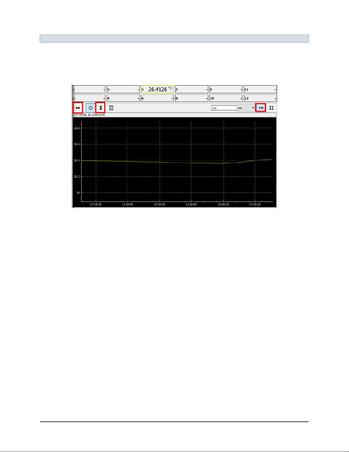
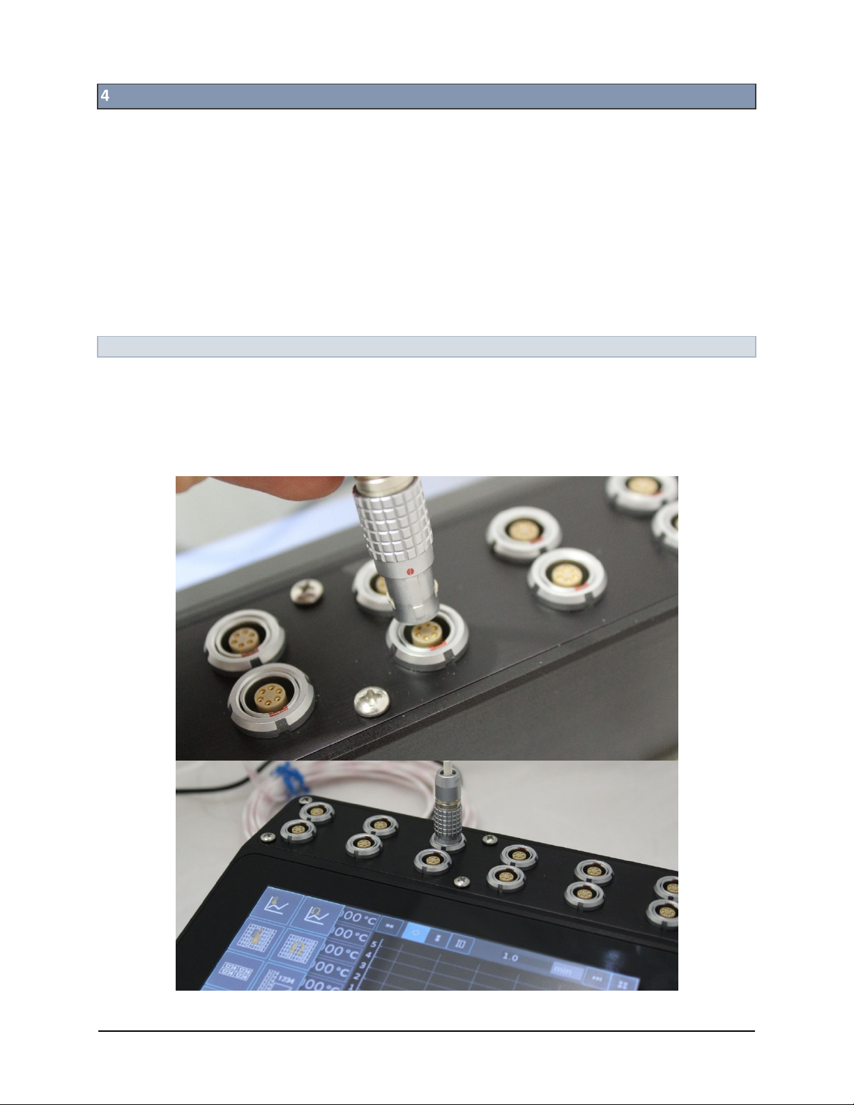
ConnectingaTemperatureProbe.................................................................................................................6
StartingUpthePT12..............................................................................................................................................7
3.1
ObtainingaReading.......................................................................................................................................7
3.2
PlottingTemperature....................................................................................................................................9
Operation.............................................................................................................................................................10
4.1
ConnectingTemperatureProbes.................................................................................................................10
4.1.1
BasicProbes.........................................................................................................................................11
4.1.2
SmartProbes.......................................................................................................................................12
4.1.3
User‐SuppliedProbes..........................................................................................................................12
4.2
ChannelMeasurementRate........................................................................................................................13
4.3
NavigatingtheUserInterface......................................................................................................................13
4.3.1
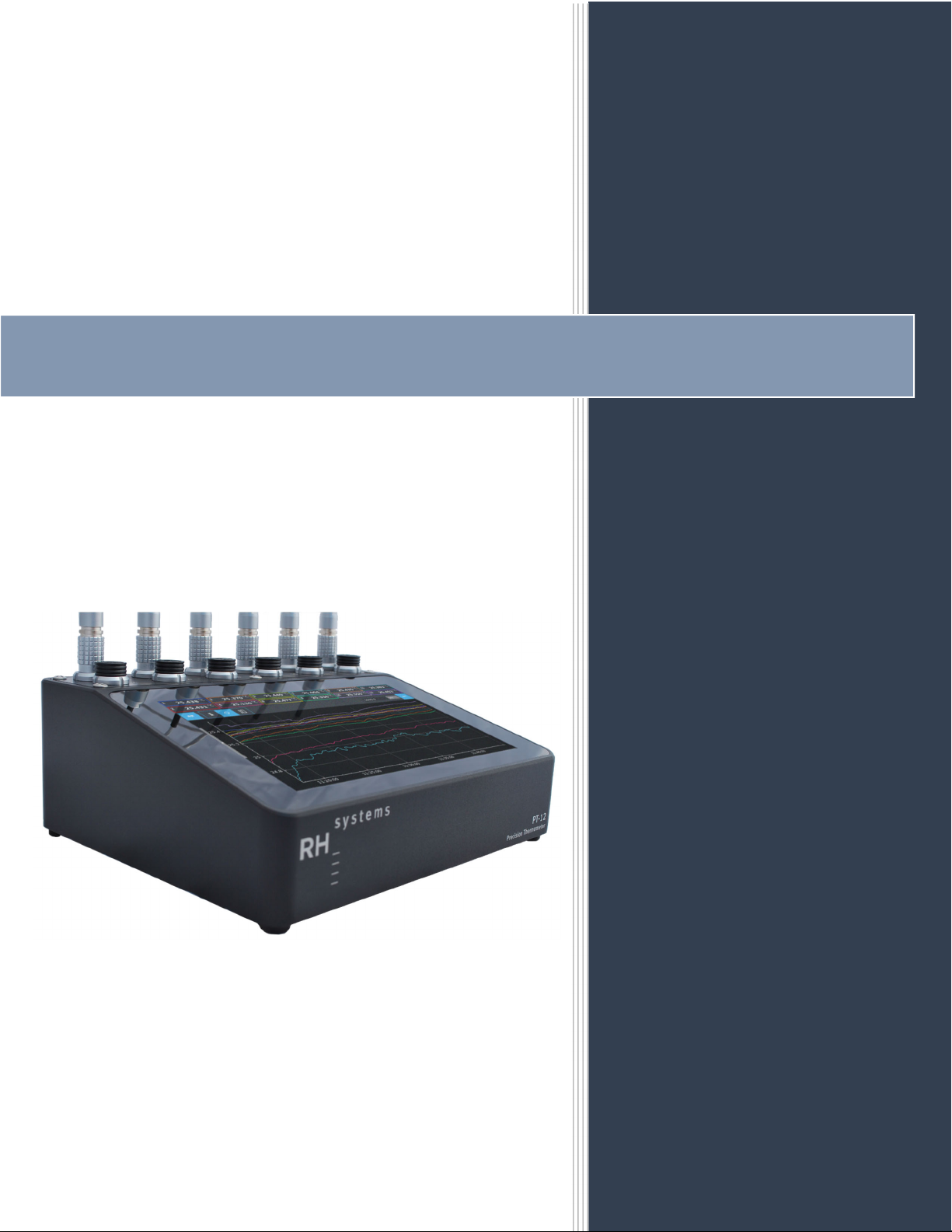
TemperatureGraphDisplayMode......................................................................................................14
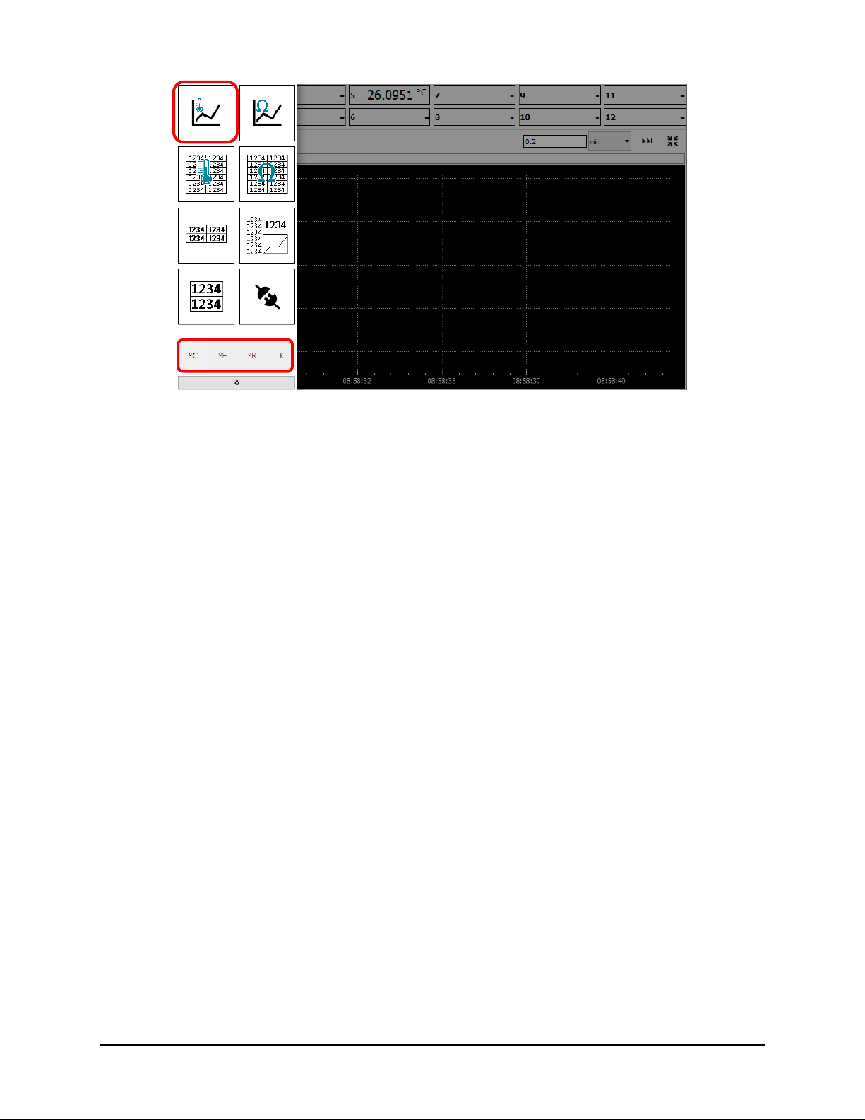
ScrollingtheGraph..........................................................................................................................15
ZoomingtheGraph..........................................................................................................................16
AxisControl......................................................................................................................................16
GraphStatistics................................................................................................................................17
4.3.2
ResistanceGraph.................................................................................................................................18
4.3.3
AllTemperatureDisplayMode............................................................................................................18
4.3.4
AllResistanceDisplayMode................................................................................................................19
4.3.5
Numeric4xDisplayMode....................................................................................................................19
4.3.6
Numeric2xDisplaymode....................................................................................................................20
4.3.7
ComboDisplayMode...........................................................................................................................21
4.3.8
ProbeStatusDisplayMode..................................................................................................................22
4.3.9
ChangingDisplayedUnitsofMeasurement........................................................................................23
4.3.10
ChangingNumberFormat...................................................................................................................23
4.4
ConfiguringtheProbes................................................................................................................................24
4.4.1
Averaging.............................................................................................................................................25
4.4.2
CurrentMode......................................................................................................................................26
4.4.3
CoefficientMode.................................................................................................................................27
Callendar‐VanDusen(CVD).............................................................................................................27
ITS90................................................................................................................................................28
4.4.4
ProbeConfigurationManagement......................................................................................................32
4.5
FileManager................................................................................................................................................34
4.5.1
CopyingLogFilestoUSBDrive............................................................................................................34
4.5.2
DeletingLogFiles.................................................................................................................................34
4.5.3
SetPreferredLoggingLocation............................................................................................................35
4.6
SystemInfo..................................................................................................................................................36
SerialCommunications........................................................................................................................................37
5.1
SerialConnections.......................................................................................................................................37
5.1.1
ElectricalWiringtotheRS‐232Ports...................................................................................................37
RS232PinOut..................................................................................................................................37
SerialConfiguration.........................................................................................................................38
5.1.2
USBtoSerialPort.................................................................................................................................38
5.2
Protocol.......................................................................................................................................................39
5.2.1
CommunicationSequenceandTerminationCharacters.....................................................................39
5.2.2
CaseSensitivity....................................................................................................................................39
5.2.3
NumericValues....................................................................................................................................39
5.3
CommandList..............................................................................................................................................40
5.3.1
SystemLevelCommands.....................................................................................................................40
5.3.2
ChannelCommands.............................................................................................................................41

Introduction
PT12Manual 7/20/2021
Page3of48
ChannelSubCommands..................................................................................................................41
5.3.3
ProbeCommands................................................................................................................................43
Calibration...........................................................................................................................................................45
Uncertainty..........................................................................................................................................................46
Specifications.......................................................................................................................................................47
DocumentHistory................................................................................................................................................48
FORSUPPORT,PLEASEEMAILSUPPORT@RHS.COMORCALL(480)926‐1955WITH
TECHNICALORCALIBRATIONQUESTIONS.

Introduction
PT12Manual 7/20/2021
Page4of48

Introduction
PT12Manual 7/20/2021
Page5of48
INTRODUCTION
ThePT12isahighlypreciseandstableplatinumresistancethermometer(PRT)basedmulti‐channeltemperature
measurementsystem.Usingacustomdesignedhighprecisionmeasurementcircuitwithfullcurrentreversaland
multiplexedsampling,thePT12provides12channelsoflowuncertaintytemperaturedataforvalidationand
calibration.
Usingoneofthreeautomaticoruserselectablecurrents,thePT12repeatedlyscansall12channels.Employinga
fullreversalcurrentsource,thePT12eliminatespolaritysensitiveerrorsnormallyinherenttoDCmeasuring
techniques.Accuracyisfurtherenhancedbyreferencingallmeasurementstoaseriesofhighaccuracy,
temperaturestableinternalreferenceresistors.
TheintegratedfirmwareallowseachchanneltobeindividuallyprogrammedwithITS‐90orCallendar‐VanDusen
(CVD)coefficientsfordirectconversionofresistancemeasurementstotemperature.Itincorporatesafullcolor,
pinchzoomtouchscreenastheuserinterface.Althoughnotrequiredforoperation,thePT12mayalsobe
connectedtoaPCoveranRS‐232orUSBinterface.

QuickStart/InitialSetup
PT12Manual 7/20/2021
Page6of48
QUICKSTART/INITIALSETUP
Thequickstartisintendedtogetyouupandrunningquickly.Foradditionalinformationseesection4Operation.
2.1 CONNECTINGATEMPERATUREPROBE
Selectanyofthesuppliedprobesandconnectittoanydesiredchannel(theremainderofthissectionwillassume
channel5).Wheninsertingtheplug,ensurethereddotslineup.

StartingUpthePT12
PT12Manual 7/20/2021
Page7of48
STARTINGUPTHEPT12
PlugintheincludedACpoweradaptertoa110‐240VACoutlet.Plugtheroundconnectorofthepoweradapter
intothebackofthePT12.Asplashscreenshouldappearinabout15secondsandthemachinewillfullyboot
withinabout30seconds.
3.1 OBTAININGAREADING
Oncethesystemfullybootsandtheuserinterfaceispresent,probe5shouldindicateareasonabletemperature
value.Allprobecoefficients(ifasmartprobe)areautomaticallyreadfromtheprobeandappliedtochannel5.
ThePT12hasseveraldifferentdisplaymodes.Itwillpowerupinthepreviousmodethatwasdisplayedonshut
down.Tochangedisplaymodes,swipewithafingerfromtheleft‐handsidetobringupthemenu.
Fromthismenu,unitsmaybechanged,oranewdisplayformatmaybeselected.
Power(12VDC,3A)USBFlashDriveUSBSerialRS‐232
Swipe

StartingUpthePT12
PT12Manual 7/20/2021
Page8of48
Toselectadisplaymode,tapthedesiredicon.Themenuwillhide,andthenewdisplaymodewillappear.Forthis
quickstartexample,selectthetopleftdisplaymodeicon(thisisthetemperaturegraphdisplaymode).
Formoreinformationseesection4.3NavigatingtheUserInterface.

StartingUpthePT12
PT12Manual 7/20/2021
Page9of48
3.2 PLOTTINGTEMPERATURE
Toaddaprobe’svaluetothegraph,taptheappropriateprobe(probe5inthiscase)onthetopportionofthe
screen.Theprobe’srecentdatawillbeplottedonthegraph.Toensurethatthedataisvisible,taptheShowAll
graphbuttons,andtheContinuousUpdatebuttontoenablethem.Whenenabled,theyarehighlightedinlight
blue.
Dragasinglefingeronthegraphtoscrollinanydirection.Usetwofingersforpinch‐zoomoperation.Foradditional
informationongraphfunctions,seesection4.3.1TemperatureGraphDisplayMode
Note:Thegraphonlyretainsthelast48hoursofdata,whilethelogfileholdsallthedatasincethelastpower
cycleorwhenloggingwaslasttoggledon.Seesections4.5FileManagerand4.6SystemInfo.

Operation
PT12Manual 7/20/2021
Page10of48
OPERATION
ThePT12measurestemperaturebyratiometriccomparisonoftheunknownresistanceofatemperatureprobeto
aseriesoftemperaturestableprecisionreferenceresistors.
Throughcustomselectionofthefourreferenceresistors,thePT12operatingrangeandprecisioncanbetunedfor
either25ΩPRTsor100ΩPRTs.Alternatively,itcanbecustomizedtocoverbothrangeswithslightlylessoverall
precision.(Formoreinformationoncustomization,contactRHSystems).ThePT12supportsthreedistinctcurrent
modeswhichcanbemanuallyorautomaticallyselected.Thethreecurrentmodesavailableareapproximately0.3
mA,0.6mA,and1mA.ThePT12willattempttogetthemostaccuratereadingpossiblewhenutilizingautocurrent
mode.
4.1 CONNECTINGTEMPERATUREPROBES
Thereare12LEMOconnectors(oneperprobe)onthePT12andanynumberofprobes(between1and12)maybe
connectedinanyorderatanygiventime.Toconnectaprobe,ensurethereddotsbetweentheplugand
receptaclearealigned,thenpushtoconnect.Pullinguponthebodyoftheplugreleasesthecatch,allowingthe
probetoberemoved.Onceinserted,thePT12willautomaticallydetecttheprobeanddetermineifitisasmart
probe(withinternalconfigurationmemory)orabasicprobe(withoutanymemory).

Operation
PT12Manual 7/20/2021
Page11of48
4.1.1 BASICPROBES
Basicprobesdonothaveinternalmemoryandusethechannel’sconfigurationforcoefficients.Ifyoumoveabasic
probefromonechanneltoanother,youwillhavetomanuallyreentertheprobecoefficients.Pins1and6are
jumperedtogetherinsidetheLEMOplugtoindicateabasicprobe.
Jumper
Wire
Image3.1.1
LEMOF66.1B.306
Basic
Probe

Operation
PT12Manual 7/20/2021
Page12of48
4.1.2 SMARTPROBES
TheLEMOconnectorofeachsmartprobeisembeddedwithaMaximIntegratedDS28EC20‐20Kb1‐WireEEPROM
chip.Thismemorychipholdstheprobe’scoefficients,serialnumber,andcalibrationdate.Whenasmartprobeis
pluggedin,thePT12automaticallydetectsitandextractsconfigurationinformationfromthechip.Manualentryof
coefficientsisnotrequiredastheconfigurationinformationtravelswiththeproberegardlessofwhichchannelit’s
pluggedinto.
4.1.3 USER‐SUPPLIEDPROBES
UsersuppliedprobesmaybeutilizedbywiringthemtoaLEMOconnector(part#FGG.1B.306).Tocreateabasic
probe,shortpin1topin6.Tocreateasmartprobe,insertaMaximIntegratedDS28EC20withpin1ofthechipto
pin1oftheLEMOandpin2ofthechiptopin6oftheLEMO.Pin3ofthechipisunusedandshouldbecutoff.See
Image3.1.2above.Bothsmartandbasicprobeswillrequireaninitialentryofcoefficients.Uponsaving,thesmart
probecoefficientswilltravelwiththeprobe.BasicprobecoefficientswillberetainedinthePT12channel.
LEMOF66.1B.306
DS28EC20
Image3.1.2

Operation
PT12Manual 7/20/2021
Page13of48
4.2 CHANNELMEASUREMENTRATE
Ittakesapproximately90msecperreadingforeachoftheattachedprobesandeachofthefourinternalreference
resistors.Meaning,iftwelveprobesareattached,thetotalmeasurementtimetoupdatealltwelvechannelsand
thefourreferenceresistorsisjustunder1.5seconds.Iffewerprobesarepluggedin,unusedchannelsare
automaticallyskipped,increasingmeasurementfrequency.Forexample,withonlyoneattachedprobe,the
approximateupdateratewouldbelessthan0.5seconds.
4.3 NAVIGATINGTHEUSERINTERFACE
ThePT12hasatouchscreeninterfacethatsupportstap,pinch/zoom,swipe,andlongpress.Theyeachhave
differentfunctionsandaresupportedonvariousdisplaymodes.
ThePT12hasseveraldifferentdisplaymodes.Itwillpowerupinthepreviousmodethatwasdisplayedonshut
down.Tochangedisplaymodesswipewithafingerfromtheleft‐handside.Thisbringsupamenuofavailable
displaymodes.
Toselectadisplaymode,tapthedesiredicon.Themenuwillhide,andthenewdisplaymodewillappear.
Thedisplaymodeiconsanddescriptions:
TemperatureGraph:Majorityofthescreenisfilledwithatemperaturegraphwith12small
temperaturevalueslistedabove.
ResistanceGraph:Majorityofthescreenisfilledwitharesistancegraphwith12smallresistance
valueslistedabove.
AllTemperatures:Showsa2x6gridwiththetemperaturesofalltwelveprobes.
Swipe

Operation
PT12Manual 7/20/2021
Page14of48
AllResistances:Showsa2x6gridwiththeresistancesofalltwelveprobes.
4xNumeric:Showsa2x2gridwiththetemperaturesandresistancesofanyfourselectedprobes.
2xNumeric:Showstemperaturesandresistancesinalargefontforanytwoselectedprobes.
Combo:Showsuptotwelveconnectedprobetemperaturesononeside,aminigraph,andalarge
numericvalue(temperatureandresistance)foranysingleprobeselected.
ProbeStatus:ShowstheprobeconnectionstatusofeachchannelofthePT12.
4.3.1 TEMPERATUREGRAPHDISPLAYMODE
Toaddaprobetothegraph,taponitsnumericvalue.Thenumericvaluewillbeoutlinedinaunique
color,andthetemperatureplotwillappearonthegraphinthatsamecolor.
NOTE:Thegraphonlyretainsthelast48hours’worthofdata,whilethelogholdsallthedatasincethelastpower
cycleorwhenloggingwaslasttoggledon.

Operation
PT12Manual 7/20/2021
Page15of48
SCROLLINGTHEGRAPH
Toscrollthegraph,dragafingerinanydirection.Alternatively,toscrollasingleaxis,dragwithintheaxisarea.

Operation
PT12Manual 7/20/2021
Page16of48
ZOOMINGTHEGRAPH
Pinchin/outwithtwofingerstozoomthegraphin/out.
Alternatively,tozoomasingleaxis,longpressontheaxisareathendrag.Fory‐axis,dragupordowntozoominor
out.Forx‐axis,dragrightorlefttozoominorout.
AXISCONTROL
ShowAll(x‐axis):Whilethebuttonisselectedthex‐axiswillbescaledtoshowalldata.
ShowAll(y‐axis):Whilethebuttonisselectedthey‐axiswillbescaledtoshowalldata.
Fixedy‐axis(semi‐auto):Whilethebuttonisselectedthey‐axisisfixed.Ifthedatagoesoutofboundsthe
y‐axisautomaticallyadjuststofitthedata.
Lockedy‐axis:Whilethebuttonisselectedthey‐axisremainsexactlyasshownwithoutanyauto
adjustment.
X‐axisWidth:Fixesthewidthofthex‐axistothespecifiedperiodoftime.
Scrollingdoesnotaffectthisvaluehowever,zoomingoverridesthisvalue.The
numericvaluedisplaysinhours,minutes,orsecondsbasedonitsassociated
drop‐downmenu.
ContinuousUpdate:Whilethebuttonisselected,thegraphwillalwaysdisplaythemostrecentvalues,
scrollingthetimeaxisasrequired.Manuallyscrollingorzoomingwilldisablethisbutton.

Operation
PT12Manual 7/20/2021
Page17of48
GRAPHSTATISTICS
Todisplaynumericalstatisticsofanycurrentlygrapheddata,longpressanddragtheboxtohighlightthegraph
datayouwishtoanalyze.Afterreleasing,thestatisticswillbeshownabovethegraph.
Scrollthestatisticaldataleftorrighttodisplaymoreinformation.

Operation
PT12Manual 7/20/2021
Page18of48
4.3.2 RESISTANCEGRAPH
Theresistancedisplaygraphisidenticaltothetemperaturegraphofsection4.3.1TemperatureGraph
DisplayMode,withtheexceptionthatvaluesshownandgraphedareproberesistancesratherthantemperatures.
4.3.3 ALLTEMPERATUREDISPLAYMODE
TheAllTemperatureDisplayModesimultaneouslyshowsalltwelvetemperaturesinthelargestfont
possible.
Unconnectedchannelsappearwithblankvalues.

Operation
PT12Manual 7/20/2021
Page19of48
4.3.4 ALLRESISTANCEDISPLAYMODE
TheAllResistanceDisplayModesimultaneouslyshowsalltwelveresistancesinthelargestfontpossible.
Unconnectedchannelsappearwithblankvalues.
4.3.5 NUMERIC4XDISPLAYMODE
TheNumeric4xDisplayModeshowsanycombinationoffourindividuallyselectablechannels.Eachofthe
fourchannelsmaybeselectedtoshowtemperatureorresistanceinalargefontwhileshowingtheoppositeina
smallerfont.

Operation
PT12Manual 7/20/2021
Page20of48
Toswapaprobe’sindicationfromtemperaturetoresistance,tapitsbottomrightbutton:
Thetemperatureandresistancevalueforthatprobeswapplaces.Totoggleresistancebacktotemperature,tap
thebuttonagain.
Tapthedrop‐downmenuonanyofthefourchannelstoselectadifferentchannel:
4.3.6 NUMERIC2XDISPLAYMODE
The2xNumericDisplayModeshowsanycombinationoftwoindividuallyselectablechannels.Eachofthe
twochannelsmaybeselectedtoshowtemperatureorresistanceinthelargestpossiblefont.Operationisidentical
tosection4.3.5Numeric4xDisplayMode.
Table of contents
Popular Thermometer manuals by other brands

SpinTouch
SpinTouch RapidScreen PLUS V3 quick start guide

Vital Baby
Vital Baby PROTECT manual

Levenhuk
Levenhuk WEZZER COOK MT60 user manual

Petit Terraillon
Petit Terraillon THERMO COLOR instruction manual

promesstec
promesstec WTR 290 Series user manual

Oregon Scientific
Oregon Scientific RAR621 user manual