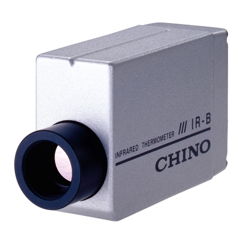
Chino IR-CZ Series User manual

INST.No.INE-555-P5
Always keep this instruction manual with the unit.
Please be sure to deliver this instruction manual
with the unit to the end user.
IR
-
CZ Series
HIGH TEMPERATURE TYPE
INFRARED RADIATION
THERMOMETER (2-color type)
[Hardware volume]
Model: IR-CZQH7

INST.No.INE-555-P5
-C1-
CONTENTS
1. Introduction................................1
1.1 Confirmation of the appearance..................2
1.2 Confirmation of the model number.............2
1.3 Confirmation of accessories........................3
2. For using safely ..........................4
2.1 Precondition for use.....................................4
2.2 Storage.........................................................4
2.3 Symbols in this instruction manual.............4
2.4 Important explanation..................................5
2.5 Warning and attention for the security ........6
3. Configuration .............................7
4. Model number............................8
4.1 Model number of the main body.................8
4.2 Model number of accessories......................9
4.3 Measuring temperature................................9
5. Names and functions of
component parts...........10
5.1 Overview...................................................10
5.1.1 Connector connection type················ 10
5.1.2 Terminal connection type ················· 10
5.1.3 Name and function of the parts··········· 11
5.2 Function part, Digital display panel..........12
5.2.1 Function part································ 12
5.2.2 Markers of digital display panel ········· 12
6. Installation................................13
6.1 Precautions in installation.........................13
6.2 Installation.................................................14
7. Targeting...................................15
7.1 Measuring distance and
measuring diameter........................15
7.2 Targeting of finder type.............................15
7.3 Focusing of finder type..............................16
8. Connections and wirings.........17
8.1 Connector connections..............................17
8.2 Terminal connections.................................18
8.3 Wirings to power terminals .......................18
8.4 Wirings to ground terminals......................18
8.5 Wirings to receiving instruments...............18
8.6 Connection example of the contact output 19
9. Operation..................................20
9.1 Self-diagnostic function ............................20
9.2 Overflow/underflow indication.................21
9.3 Clamp indication .......................................21
10. Maintenance and check.........22
10.1 Periodical checking. ................................22
10.2 Trouble shooting......................................22
10.2.1 Measuring value not displayed or
displayed lower ········· 22
10.2.2 Measuring value displayed higher······ 22
10.2.3 Display fluctuated ························ 22

INST.No.INE-555-P5
-C2-
11. Reference.................................23
11.1 Emissivity table.......................................23
11.1.1 Emissivity table (= 0.65µm)·········· 23
11.1.2 Emissivity table (= 0.9µm) ············ 24
11.1.3 Emissivity table (= 1.55µm)··········· 24
12. General Specifications...........25
12.1 Thermometer ...........................................25
12.2 IR-CZQH series outside dimensions.......26
12.2.1 Connector connection type·············· 26
12.2.2 Terminal connection type················ 26
12.3 Accessories outside dimensions ..............27
12.3.1 Connector type connecting cable
(Model : IR-ZZRC□□□) ········ 27
12.3.2 Terminal type connecting cable
(Model : IR-ZCRT□□□) ········ 27
12.3.3 Compatible cable with IR-CA
(Model : IR-ZZCC)········· 27
12.3.4 Compatible attachment
(Model : IR-ZCZS)········ 28
12.3.5 Eyepiece filter (Model : IR-ZCLF) ···· 28
12.3.6 Protective case (Hard type)
(Model : IR-ZCCH) ······ 29
12.3.6-1 Connector type (IR-ZCCHCZ)······· 29
12.3.6-2 Terminal type (IR-ZCCHT)··········· 29
12.3.7 Protective case (Soft type)
Model : IR-ZCCS ········· 30
12.3.7-1 Connecter type (IR-ZCCSCZ) ······· 30
12.3.7 -2 Terminal type (IR-ZCCST) ·········· 30
12.3.8 Sealing window (IR-ZW□)·············· 30
12.3.9 Water-cooling flange
(Model : IR-VSW)···················· 31
12.3.10 Air-purge hood (Model : IR-ZCAP)·· 31
12.3.11 Cooling water plate
(Model : IR-ZCWC)················ 31
12.3.12 Flange installation plate
(Model : IR-ZCAF)············· 32
12.3.13 Simple type universal head
(Model : IR-ZMS) ·············· 32

INST.No.INE-555-P5
-1-
1. Introduction
The IR-CZ series is a high temperature type infrared radiation thermometer (2-color type) using a hybrid
element converting functions enabling digital temperature display and parameter programming are
built-in. The thermometer is focusable and has long-distance factor for free installation. The response
time is 20ms suitable to on-line measurement.
The radiation energy collected through the objective lens is transmitted to the element is converted into an
electrical signal. The element output is digitally converted and processed through emissivity
compensation, linearizer and modulation. The standardized final output is 4 to 20mA DC. Functional keys
make programming or selection of emissivity, signal modulation and alarm function easy.
2 types of connection by terminals or a connector are available in this thermometer depending on a
connection cable. Various options and accessories are prepared for every kind of applications.
This instruction manual is explaining only "Hardware volume" for using high temperature type infrared
radiation thermometer (2-color type) Model : IR-CZQH correctly and safely, read the separate instruction
manual [IR-CZ series Software volume].
◆Request to the operator of the thermometer
This instruction manual describes the maintenance of the thermometer, too.
Keep this instruction manual with the thermometer.
If you have unclear points or need technical assistance, please contact your sales agent of CHINO
Corporation.
1. The information in this manual is subject to change without notice and does not represent a
commitment on the part of CHINO Corporation.
2. No part of this manual may be reproduced or transmitted in any form or by any means, electronic or
mechanical, including photocopying and recording, for any purpose other than the purchaser's
personal use without permission of CHINO Corporation.
3. CHINO Corporation shall not be liable for any operation results.
Preface

INST.No.INE-555-P5
-2-
◆Confirmation after the packing box opening a letter
Please confirm the following before use after opening a letter with this product by all means.
Please contact purchase or our nearest office by any chance if there are doubts.
1.1 Confirmation of the appearance
In the appearance, please confirm that a product does not have damage.
1.2 Confirmation of the model number
Please confirm that the form cord (serial number plate) of the product which had you purchase it does not
have a mistake.
Model number : IR-CZQH 7 □
IR-CZQH : High temperature type infrared radiation thermometer (2-color type)
7 : Distance factor L/D
7 : 200 with field diaphragm ø10
□ : Connection type
N : Connector connection type
T : Terminal connection type
Serial number plate and pasting place
The serial number plate is attached on the position of the chart below.
IZ202Q999
QH7N 900-3500
IR-CZ RANGE No.
IZ202Q999
QH7N 500-3500
IR-CZ RANGE No.
Serial number plate
900
-
3500

INST.No.INE-555-P5
-3-
1.3 Confirmation of accessories
Because it is attached the following accessories to a product, please confirm it.
Article name Quantity Remarks
IR-CZ Series
HIGH TEMPERATURE TYPE
INFRARED RADIATION
THERMOMETER (2-color type)
[Hardware volume]
1book This book
IR-CZ Series
HIGH TEMPERATURE TYPE
INFRARED RADIATION
THERMOMETER (2-color type)
[Software volume]
1book Separate volume
◆Notice
1. When you take this product out of a packing box, please be careful not to drop it.
2. When you transport this product, enter the packing box for this product, and you put it in the outer
box which spread a cushion all more, and please transport it.
In consideration of such a case, please keep the packing box for this product.
3. When you do not use this product for a long term, pleas avoid direct rays of the sun, and keep it at
normal temperature and at a place with a little dust.

INST.No.INE-555-P5
-4-
War ning
2. For using safely
Please read and understand the following instructions to have you use this product safely.
2.1 Precondition for use
1) The working temperature range of this product is -10 to 60 ºC.(no condense dew)
2) Do not use the thermometer in dusty places, etc. Remove the dust after using it.
3) Please avoid the use in atmospheres such as a dust, garbage, the corrosive gas.
4) This product is a precision instrument. Please avoid the use in the place as follows.
Use at the place that a temperature change has a big.
Use at the humid place.
Use at near the heavy electric appliance circuit or the place of the big instruction disorder.
Use at the place with the mechanical vibration and impact.
5) The person to use, please really read this instruction manual. In addition, please keep it carefully in the
place that you can read it anytime. There is need to have you understand the instructions of this
product, basic operation enough.
2.2 Storage
1. Do not store the thermometer in hot and humid places.
2. For failures of the thermometer, don’t overhaul it by yourself, and contact your sales agent of
CHINO Corporation.
2.3 Symbols in this instruction manual
The symbols shown below are used depending on important degrees for using the thermometer safely and
avoiding unexpected situations.
Important
degree Symbols Contents
1This symbol is indicated with a title for an explanation with .
2Indicates important information that must be observed to avoid the risk of
fire or electric shock or other dangers that may result in serious personal
injury or death, or damage to this product.
3Indicates important information that must be observed to avoid the risk of
personal injury or malfunctions of this product.
4Indicates supplementary information that the operator is recommended to
understand.
5Indicates supplementary information or a reference to an operation.
6It is a grounding terminal. Please connect the grounding terminal to
protection grounding by all means.
R e m a r ks
Reference
Caution
Warning

INST.No.INE-555-P5
-5-
2.4 Important explanation
1) Confirmation of the power supply voltage and the connection
Please confirm it about the following before supplying a power supply.
The power supply voltage matches the rating voltage.
Connection is right.
Grounding is carried out, and so on.
2) Setting of the overcurrent protection device
This product does not have power switch. Please install an overcurrent protection device (including the
breaker) in accord with rating specifications in the power supply to supply to this product.
3) Protection of the terminal part
Particularly in the case of a terminal connection type (model : IR-CZQH7T), for prevention of electric
shock, please put safe measures that prevent touching the terminal part of this product directly.
4) Setting of the safety device
About the use to the facilities that a serious loss is predicted by this product and peripheral device
breaking down, please put a fail-safe design on the setting of the safety device to evade those losses by
all means and end product side.
In addition, please never use it for important facilities affecting human life, atomic energy, aviation,
the space.
5) Do not touch the product inside
Please do not touch the inside of this product, and do not put tools. There might be an electric shock
and the injury.
6) Power supply block at the time of the doubt
When this product generates bad smell, abnormal noise, smoke, and it becomes the abnormal high
temperature, it is dangerous at all. You intercept a power supply promptly, and please contact purchase
or our nearest office.
7) Prohibition of repair, the remodeling
Repair and the remodeling such as the parts exchange by other than the serviceman whom we
authorized are prohibited. When repair and remodeling are necessary, please contact purchase or our
nearest office.
8) Strict observance of the instruction manual
Please follow this instruction manual to have you use this product safely definitely.
About any request including an injury, the damage and the loss that occurred by wrong use, we do not
take responsibility at all. Thank you for your understanding beforehand.
9) Disposal of this product
When you discard this product, please obey the regulation of each local government.
For serious accident prevention, please read and understand these contents by
all means.

INST.No.INE-555-P5
-6-
2.5 Warning and attention for the security
When you use this product, you follow the following matters by all means, and please use it definitely.
In addition, please keep this instruction manual carefully in the place that you can read anytime.
shows an act of the prohibition.
Warning (May cause death or serious injury)
Don’t operate this thermometer in places where combustible or volatile gas is
existed.
It is extremely dangerous to use the thermometer in such environment.
For the measurement of object exceeding 1500ºC, make sure to use the
eyepiece filter. However, when you feel glare on the measurement of objects
lower than 1500ºC, use the eyepiece filter (Model: IR-ZCLF).
When connecting power to the power terminals, make sure that all mains is
turned off to prevent an electric shock.
Don’t use the thermometer if it was broken, smoking or nasty smelling.
These may cause fire. For such abnormal condition, turn off the power switch
at once and contact your sales agent of CHINO Corporation.
Laser may damage your eyes. Don’t stare into a laser beam. Make sure to
target the laser when you want to decide the center of the measuring object
only and to go off it after the center of the measuring object is decided.
Never take the thermometer apart or convert it.
These may cause trouble and danger.
Caution (May cause injury or physical damage)
Be careful not to give vibration or impact to the thermometer. Install the
thermometer by keeping it as far as possible from an inductive oscillator or
electric power line.
Do not use the thermometer in dusty places, noisy places and static electricity
places.
Do not wire the connection cable near a noise occurrence resource, relay drive
line, high frequency line and power line.
Do not bundle the connection cable with the line that noise is doubling, and do
not store it into the same duct.
Read the entire contents in this instruction manual to have the thermometer function
perfectly.
!
!
!
!
!
!
!
!
!
!
!

INST.No.INE-555-P5
-7-
3. Configuration
About the external input/output, the model number has 4-20mA DC analog output, the RS485 serial
communication built-in.
About digital contact output (DO),
1) The connector connection type (model :IR-CZQH7N) has one point of contact output (DO)
built-in.
2) The terminal connection type (model :IR-CZQH7T) does not have it built-in with contact output
(DO) .
Reference
The accessories are put together depending on a use variously.
Please refer to the instruction manual of each accessory.
IR
-
CZQH7
□
Compatible attachment
IR
-
ZCZS
Using for installation to the protection case
Using for securing of comparability with IR-CAseries
Sealing window
IR-ZW□
Water-cooling flange
IR
-
VSW
Air-purge hood
IR
-
ZCA
P
Water-cooling plate
IR
-
ZCWC
Flange installation plate
IR
-
ZCAF
Protective case
(Hard type)
IR-ZCCH
□□
Protective case
(Soft type)
IR-ZCCS
□□
Simple type
universal head
IR-ZMS
Instrument
Setting display
with power supply
IR-GZ
Recorder
Controller
24V DC power supply
IR-ZFEP
It is unnecessary at the time of
a combination with IR-GZ.
External input/output
Eyepiece filter
IR-ZCLF

INST.No.INE-555-P5
-8-
4. Model number
4.1 Model number of the main body
IR-CZ QH 7 □
Series
IR-CZ Series
Model
QH : High temperature type infrared radiation thermometer
(2-color type)
・4 to 20mA DC Analog output
・RS485 Serial communication
・One point of contact output (Connector connection type only)
Distance factor L/D (Measuring distance/Measuring diameter)
7 : 200 with field diaphragm ø10
Connection type
N : Connector connection type
T : Terminal connection type
R e m a r ks ・The terminal connection type (model :IR-CZQH7T) does not have a contact
output (DO) built-in.

INST.No.INE-555-P5
-9-
4.2 Model number of accessories
Accessories Model Reference
Compatible attachment IR-ZCZS Used for Protective case (Hard type, Soft type)
Protective case(Hard type) IR-ZCCH CZ: Connector T: Terminal
Protective case(Soft type) IR-ZCCS CZ: Connector T: Terminal
Sealing window IR-ZW0 Quartz glass
Water-cooling plate IR-ZCWC
Air-purge hood IR-ZCAP
Water-cooling flange IR-VSW
Flange installation plate IR-ZCAF
Eyepiece filter IR-ZCLF
Connecting cable
(Connector type) IR-ZZRC :Designated length (m)
Connecting cable
(Terminal
type)
IR-ZCRT :Designated length (m)
Connection cable compatible
with IR-CA IR-ZZCC Used for conversion to IR-CZ of the
connection cable for IR-CA
Simple type universal head IR-ZMS
4.3 Measuring temperature
Name Distance factor L/D Model Measuring
temperature range
High temperature
type infrared
radiation
thermometer
(2-color type)
Distance factor L/D is 200,
with field diaphragm ø10 IR-CZQH7□ 900 to 3500 ºC
(Single-color type : 500 to 1400 ºC)
R e m a r ks ・Compatible attachment (model: IR-ZCZS) is used at the time of the installation of
the main body to a protective case (software type (model: IR-ZCCS, hardware
type (model: IR-ZCCH ).
・Setting compatibility (the amount of optical axis, installation hole position, etc.) with
the IR-CA series is secured by using compatible attachment (model: IR-ZCZS).

INST.No.INE-555-P5
-10-
5. Names and functions of component parts
5.1 Overview
5.1.1 Connector connection type (Model: IR-CZQH7N)
5.1.2 Terminal connection type (Model: IR-CZQH7T)
(5)
(3)
(7)
(4)
(2)
(1)
(11) (12)
(13)
(14) (9)
(10)
(8)
(6)
Function part cover disassembly
(15)

INST.No.INE-555-P5
-11-
5.1.3 Name and function of the parts
Name Function
(1)Cover Glass An optical glass for protecting the objective lens from scratches,
smudges, etc.
(2)Objective lens tube For focusing in a measuring area. This tube has the indication of
distance.
(3)Distance indication plate For indication of distance (0.5, 0.6, 0.8, 1.25mm, ∞)
(4)Distance marker For marking the distance indicated on the above plate.
(5)Screw of objective lens tube For fixation of the objective lens tube.
(6)Eyepiece lens tube For focusing in the target mark inside the viewfinder.
(7)Function part cover The cover of the function keys. Because it is fixed with upper part
M3 fixation screw, when a setting change is necessary, you take it
off, and please setting-change it.
(8)Digital display panel Main display: LCD 4 digits, Sub display: LCD 4 digits,
Status marker: Alarm status, Sub marker: Emissivity (Emissivity
ratio), Measuring unit: ºC or ºF
(9)Serial number plate Manufacturing plate of displayed Model No., measuring
temperature range and manufacturing serial No. In the case of an
inquiry, please tell me each item by all means.
(10)Connecter Connect the thermometer by using the exclusive cable (IR-ZZRC
or IR-ZCRL)
(11)Screw hole for tripod A 1/4-20UNC screw hole for fixing a tripod or a simple type
universal head.
(12)Screw holes for installation of
thermometer M4 (depth 4mm) screw holes for installation of the thermometer
Use these screw holes for housing the thermometer in a protective
case.
(13)Screw holes for installation of
compatible attachment M4 (depth 4mm) screw holes of four place for installation the
compatible attachment.
(14)Function keys 5 function keys for programming parameters.
(15)Terminal board Connect the thermometer by using the exclusive cable (IR-ZCRT)
or the recommended cable.

INST.No.INE-555-P5
-12-
5.2 Function part, Digital display panel
5.2.1 Function part
Name Function Indications
(1)Entry key Used to store the selected or programmed parameter.
(2)Select key Used to select a parameter menu in the operating mode or the
engineering mode.
(3)Up key Used to select a parameter in the parameter selection mode or to
scroll numeric characters in the parameters programming mode.
(4)Down key
(5)Next key Used to select a parameter in the parameter selection mode or to
shift a digit for numeric entries to the right in the parameters
programming mode.
5.2.2 Markers of digital display panel
Name Function Marker Indications
(6)Main display
At the time of the measurement, measurement value of
the thermometer is displayed, at the time of setting, a
setting item, a choice level, choice item is displayed with
LCD 4 figure.
(7)Sub display At the time of the measurement, a menu chosen with SEL
key is displayed, at the time of the setting, a setting item
is displayed with LCD 4 figure.
(8)Status marker
It is turned on at the time of lower limit temperature
alarm outbreak. AL “AL”
It is turned on at the time of upper limit temperature
alarm outbreak. AH “AH”
(9)Sub marker Will light when the sub display shows an emissivity
(ratio). Single color type is the emissivity (ε) and 2-color
type is the emissivity ratio (εr).
ε(εr)“ε” “εr”
(10)Temperature
unit Temperature unit of ℃or ゚F is displayed. C F “C” “F”
(3)
(4)
(5)
(10)
(7)
(6)
(8)
(2)
(1)
(9)
ENT
SEL

INST.No.INE-555-P5
-13-
6. Installation
6.1 Precautions in installation
This product IR-CZQH7□ is a precision instrument. Please install it on the occasion of setting with care
to the following item.
Vibration and impacts
Vibration or impacts reduces the liability of the thermometer and causes an unstable
measurement by the targeting shake to a measuring surface.
If you install the thermometer in the place where vibration or impacts exist, its
careful periodic inspection is requested.
Induction
The thermometer is designed for anti-induction but install it as far as possible from
an induction heating generator or power line.
Working temperature
The working temperature of the thermometer is -10 to 60ºC. If the ambient
temperature is high or if the temperature of the thermometer exceeds the maximum
working temperature by reflection from a high temperature substance, etc.,
water-cooling of the thermometer is absolutely necessary.
When the temperature of the thermometer does not exceed but closely reaches to the
maximum working temperature, water-cooling of the thermometer is recommended
for maintaining of the reliability of the thermometer.
Optical path
Select a place for installation of the thermometer, where water-drops, dust, smoke,
steam, etc. would not enter between the thermometer and a measuring surface.
If such place cannot be selected and the affection by existence of such substances
cannot be ignored, blowing-out of such substance with air-purge is necessary.
Disturbances to make indication of measured value higher
Select a place for installation of the thermometer, where sunlight, light of
incandescent lamp, flame, heat radiation from a high temperature substance, etc. is
not reflected to the measured surface and the cover glass of the thermometer. When
such light is reflected, higher temperature than the exact one will be indicated. (The
affect by such reflection will be great for the measurement of low temperature.) If
such place cannot be selected, shade the thermometer or take similar precautionary
measures.
Caution

INST.No.INE-555-P5
-14-
6.2 Installation
Install the thermometer to a tripod, universal head, protection case, or mounting plate etc., by using screw
holes for tripod (1/4-20UNC) or screw holes for installation (4-M4) at the bottom side.
When you install it in the protective cases of exclusive accessories, it is necessary to install it in the
protection case after having attached a compatible attachment (model: IR-ZCZS).
Please read the operation manual for an accessory when instilling it by using the exclusive accessories.
Don’t use the thermometer in the following places.
1) Dusty place or a corrosive gas atmosphere.
2) Noisy and static electricity
3) Places where the ambient temperature is higher than 60°C or lower than -10°C.
4) Places where the ambient temperature changes abruptly, or high humid places.
5) Places where there are inductive oscillator or electric power line
6) Places where there are mechanical vibrations and impacts.
7) Places where combustible or volatile gas is existed.
Screw hole for tripod 1/4-20UNC(depth 4)
Screw holes for installation 4-M4 (depth 4)
Screw holes for attaching compatible
attachment 4-M4 (depth 4)
Caution

INST.No.INE-555-P5
-15-
7. Targeting
7.1 Measuring distance and measuring diameter
The relation of the measuring distance and the measuring diameter is defined by the distance factor as
shown in the following formula.
Place the thermometer at the measuring distance computed by the above formula.
Considering the dislocation of the optical axis, take the measuring area more than 1.5 times the measuring
diameter.
7.2 Targeting of finder type
Look into the eyepiece lens and turn the eyepiece lens tube to focus the following targeting mark.
◆Upper view of main body
Measuring diameter of distance factor 200 is inner circle inside.
Measuring distance (mm) = Distance factor x measuring diameter (mm)
Reference
Rough standard for measuring distance and measuring diameter (With field diaphragm Ø10)
Distance
factor Measuring distance (mm)
500 1000 2000
200 Ø2.5 Ø5 Ø10
For the measurement of object exceeding 1500ºC, make sure to use the eyepiece
filter (Model: IR-ZCLF). However, when you feel glare on the measurement of
objects lower than 1500ºC, use the eyepiece filter (Model: IR-ZCLF).
Eyepiece lens
tube
Warning

INST.No.INE-555-P5
-16-
7.3 Focusing of finder type
Focus a measuring object by turning the objective lens tube by its distance indication plate and the
distance marker.
When an objective lens tube does not turn around, you should confirm a screw for objective lens tube,
and please turn it after having loosened it when it closes.
Make sure that the measuring area should be larger than the targeting mark (Recommended area: For the
distance factor of 200 - More than 1.5 times the targeting mark), and then fix the objective lens tube by
screwing the attached screw (with a hexagon hole) into the fixing screw hole of the objective lens tube.
Distance marker
Screw of objective lens tube
Distance adjustable marker
Objective lens tube
◆Upper view
◆Enlarged figure of distance adjustable marker
Distance adjustable marker
Caution
For the installation of the thermometer with a protective case, house the thermometer to
the protective case after adjusting the focus of the thermometer.

INST.No.INE-555-P5
-17-
Key position
Connector
8. Connections and wirings
8.1 Connector connections (Model : other than IR-CZQH7N)
◆Connection of the exclusive cable (model : IR-ZCRC)
The connections are completed by simply connecting the connector of the cable (IR-ZCRC) to the
connector placed at the rear side of the thermometer.
(1) For the connection, align the slit in the connector of the cable and the key position in the connector
of the thermometer and firmly insert the cable connector, and then turn the coupling ring clockwise
until it is locked.
(2) For the disconnection, turn the coupling ring counterclockwise for releasing its locked status, and
pull the connector of the cable forward.
Connector pin No. Signals
A DC power supply 24V DC (+)
BDC power supply 24V DC (-)
C Current output of temperature 4 to 20mA DC (+)
DCurrent output of temperature 4 to 20mADC (-)
E Serial communication RS485 SA
F Serial communication RS485 SB
G Contact output 1 (+)
HContact output 1 (-)
JOption (Do not use it)K
L
M Ground
Warning
Slit
Coupling ring
Connector of the exclusive cable IR-ZZRC
When connecting power to the power terminals, make sure that all mains
power is turned off to prevent an electric shock.
This manual suits for next models
2
Table of contents
Other Chino Thermometer manuals

Chino
Chino IR-AH Series User manual

Chino
Chino IR-BAT Series User manual

Chino
Chino IR-E Series User manual

Chino
Chino IR-SA Series User manual

Chino
Chino IR-FA Series User manual

Chino
Chino IR-BZ Series User manual

Chino
Chino IR-CAK User manual

Chino
Chino TP-S Easy Thermo User manual

Chino
Chino IR-H Series User manual

Chino
Chino IR-CA series User manual