manuals.online logo
Brands
  1. Home
  2. •
  3. Brands
  4. •
  5. Rheem
  6. •
  7. Water Heater
  8. •
  9. Rheem RUUD AdvantagePlus Operating instructions

Rheem RUUD AdvantagePlus Operating instructions

Other Rheem Water Heater manuals

Rheem 491 Technical Document

Rheem

Rheem 491 Technical Document

Rheem RSID50 User manual

Rheem

Rheem RSID50 User manual

Rheem 115 User manual

Rheem

Rheem 115 User manual

Rheem RUUD Commercial Booster User manual

Rheem

Rheem RUUD Commercial Booster User manual

Rheem Light Duty Commercial Electric Water Heater User manual

Rheem

Rheem Light Duty Commercial Electric Water Heater User manual

Rheem HB Series User manual

Rheem

Rheem HB Series User manual

Rheem TRITON GHE80SU-130A User manual

Rheem

Rheem TRITON GHE80SU-130A User manual

Rheem 310 Series Technical Document

Rheem

Rheem 310 Series Technical Document

Rheem Indirect Water Heater User manual

Rheem

Rheem Indirect Water Heater User manual

Rheem Single Element User manual

Rheem

Rheem Single Element User manual

Rheem ELECTRIC WATER HEATERS Quick start guide

Rheem

Rheem ELECTRIC WATER HEATERS Quick start guide

Rheem GG50T06PVT User manual

Rheem

Rheem GG50T06PVT User manual

Rheem Energy Miser RH DV50FV User manual

Rheem

Rheem Energy Miser RH DV50FV User manual

Rheem 627 series Technical Document

Rheem

Rheem 627 series Technical Document

Rheem Guardian PowerVent User manual

Rheem

Rheem Guardian PowerVent User manual

Rheem PH-16(FISN)(FISP) User manual

Rheem

Rheem PH-16(FISN)(FISP) User manual

Rheem Premier Hiline Technical Document

Rheem

Rheem Premier Hiline Technical Document

Rheem RT1000C6 Technical Document

Rheem

Rheem RT1000C6 Technical Document

Rheem 86H-25 Installation guide

Rheem

Rheem 86H-25 Installation guide

Rheem 38.5 User manual

Rheem

Rheem 38.5 User manual

Rheem Water Star Technical Document

Rheem

Rheem Water Star Technical Document

Rheem RHP-5207C Series Technical Document

Rheem

Rheem RHP-5207C Series Technical Document

Rheem Lazer Classic Series Instruction Manual

Rheem

Rheem Lazer Classic Series Instruction Manual

Rheem PRO+G48-60N RH60 User manual

Rheem

Rheem PRO+G48-60N RH60 User manual

Popular Water Heater manuals by other brands

clage German pool CEX13 operating instructions

clage

clage German pool CEX13 operating instructions

Noritz proTough NR98SV installation manual

Noritz

Noritz proTough NR98SV installation manual

DeDietrich KALIKO TWH 200 EV Installation and service manual

DeDietrich

DeDietrich KALIKO TWH 200 EV Installation and service manual

veito FLOW Installation and operating instructions

veito

veito FLOW Installation and operating instructions

ICI Caldaie COSMOGAS AGUATANK 150 Instructions for installation, use and maintenance manual

ICI Caldaie

ICI Caldaie COSMOGAS AGUATANK 150 Instructions for installation, use and maintenance manual

Savio Laser 11 A Instruction manual for installation and use

Savio

Savio Laser 11 A Instruction manual for installation and use

Kenmore 153.582400 Use & care guide

Kenmore

Kenmore 153.582400 Use & care guide

STIEBEL ELTRON Eltronom SHU 5 S Operating and installation instructions

STIEBEL ELTRON

STIEBEL ELTRON Eltronom SHU 5 S Operating and installation instructions

clage E-Mini Series Operating and installation instructions

clage

clage E-Mini Series Operating and installation instructions

Solar SunX 317365-002 instruction manual

Solar

Solar SunX 317365-002 instruction manual

Bradford White EF Series Service manual

Bradford White

Bradford White EF Series Service manual

Dimplex ECSd125-580 Installation and user instructions

Dimplex

Dimplex ECSd125-580 Installation and user instructions

Dux 32FCR6N installation manual

Dux

Dux 32FCR6N installation manual

Noritz N-132M Owner's guide and installation manual

Noritz

Noritz N-132M Owner's guide and installation manual

TESY GCV7/4S 10047 Instructions for use and maintenance

TESY

TESY GCV7/4S 10047 Instructions for use and maintenance

A.O. Smith Gphe 50 instruction manual

A.O. Smith

A.O. Smith Gphe 50 instruction manual

Rinnai REP199i Installation and operation manual

Rinnai

Rinnai REP199i Installation and operation manual

Toyotomi Oil Miser OM-148 (Type D) Operation and maintenance instructions

Toyotomi

Toyotomi Oil Miser OM-148 (Type D) Operation and maintenance instructions

manuals.online logo
manuals.online logoBrands
  • About & Mission
  • Contact us
  • Privacy Policy
  • Terms and Conditions

Copyright 2025 Manuals.Online. All Rights Reserved.

TECHNICAL SERVICE DEPARTMENT
Technical Service Bulletin
1-800-432-8373
AdvantagePlus Troubleshooting
When first diagnosing an AdvantagePlus, check the following:
•If the unit is not operating, is the power on?
•Is the unit gas valve turned on?
•Is the unit thermostat temperature setting high enough to call for heat?
•What is the temperature of the water in the tank?
•Is there "LOC" in the LED panel window? (Press red reset button on front panel. Allow retrying for
ignition. Then diagnose based on the table below.)
LINE LED is off; does not have 120VAC
Explanation: This LED monitors incoming AC line voltage. The LED is ON when 120VAC line voltage is present
on the control board. If the wall plug is properly wired, you will see a green LED light on the bottom left hand
corner of the control board.
At a minimum, check the following:
1. Plug in unit; check circuit breaker
2. Polarity is correct or ground is missing on wall plug
3. Re-seat CN1 Molex plug on control board
4. Verify display ribbon cable is connected to main
board and display board
Is there 120VAC at the
black and white wires to
connector 1 (CN1)?
Yes
N
oVerify power at wall plug or line connection
1. Verify power connection in box on heater.
2. Check and remove wall plug. Ensure the black lead is to
the brass screw; the white lead is to the silver screw; and
there is a ground wire present.
Continue to next step
AdvantagePlus Fault Tree Troubleshooting
1706.doc
2
24 VAC LED is off; does not have 24VAC out of the transformer
Explanation: This LED monitors voltage from the transformer. The LED is ON
when secondary 24VAC is present. You may have line voltage and not have the
24VAC line lit if the board is bad.
At a minimum, check the following:
Transformer wiring
Reseat plugs on control module (CN4)
Unit appears to be OK. Recycle power.
Is the green LED on
the bottom left side
of the control board
lit up?
Yes
No Replace control board
Remove and check wall plug. Ensure the black lead is to the brass
screw; the white lead is to the silver screw; and there is a ground
wire present.
Check the wiring connections inside the blue plastic junction box
on the heater. Black to black, white to white; ground to green.
If the green LED is not ON, then the unit thinks polarity is not
correct.
Continue to next step
Is there 120 VAC line
voltage from the board to
the transformer?
Yes
N
oReplace board
Measure for 120 VAC at the black and white wires of CN4
AdvantagePlus Fault Tree Troubleshooting
1706.doc
3
ECO/VENT SWITCH; Water in tank is too hot or vent gas is too hot or low water cut off switch has tripped
Explanation: This LED monitors the ECO loop in the tank
water, the low water cut off switch and the vent over
temperature switch. LED is ON when all three of these safety
devices are normal. The loop is electrically closed.
At a minimum, check the following:
1. Water temperature
2. Vent temperature at exhaust coupling
3. Low water level in tank
Follow this process in sequence: Recycle power to
the water heater. If the blower does not come on, go to step #1; if the blower is does come on, go
to step #2.
Unit appears to be fine. Recycle power and try again.
Is there 24 VAC from
the transformer to the
board?
Yes
No Replace transformer
Measure for 24 VAC at the blue and yellow wires of CN4
Reset over temp switch. Check venting for signs of heat damage. Monitor unit for poor combustion.
1. Is the vent over
temperature switch
tripped? (Vent temp
switch is normally
closed. When the vent
reaches @ 1800F, the
switch will open.)
Yes
N
oContinue to next step
Remove the two wires on the vent switch. Verify continuity thru two
terminals at the vent temp switch on the exhaust. Press red button
to force manual reset if there is no continuity.
AdvantagePlus Fault Tree Troubleshooting
1706.doc
4
Fill unit with cold water. Recycle power and attempt to relight burner.
2. Is the ECO activated?
(Verify the water
temperature in the tank
by pressing the red
button on the display.)
Yes
No Unit appears to be fine. Recycle power.
ECO will trip at 2000F and automatically reset when the water
cools to 1600F.
Measure the water temperature from the T&P valve. If the water
temp exceeds 1600F, then flush cold water thru the tank.
Recycle power.
3. Does the ECO have
continuity?
Yes
No Replace ECO/Temp probe
Disconnect CN3. Check continuity of both red wires thru the
ECO/Temp Probe.
AdvantagePlus Fault Tree Troubleshooting
1706.doc
5
Unit appears to be fine. Recycle power.
5. Is the low water cut
off switch working
properly? (It has power
going to it; so now we
are checking if the
switch has continuity.)
Yes
No
Disconnect green wire from vent overtemp switch. Leaving the
Molex connected at the low water cut off, check for continuity
between the two green wires at the low water cut off switch. If you
has continuity, then follow “yes”.
1. Disconnect the Molex and jumper the two green wires.
2. Recycle power.
3. If the unit goes to main burner, then replace low water cut off switch.
4. If the unit does not go to main burner, then recheck step # 4 above.
Fill unit with cold water. Recycle power and attempt to relight burner.
4. Is the low water cut
off switch activated?
(Make sure the tank is
full of water by bleeding
@ a gallon from a near
by hot water faucet.)
Yes
No Verify 24VAC power from transformer
splice.
Recycle power and verify 24
VAC between the black and
red wires at the low water cut
off switch connection.
AdvantagePlus Fault Tree Troubleshooting
1706.doc
6
PRESSURE SWITCH; Air pressure switch or blower motor not operating properly; problem with venting.
Explanation; Monitors the positive air pressure
switch. Means there is sufficient combustion airflow.
The LED is ON when the pressure switch is closed.
Fault indicates insufficient airflow thru the venting
and blower system.
At a minimum, check the following:
1. Venting blockage (air in and air out)
2. Blower not operating
3. Pressure switch stuck open
4. Vinyl tubing to pressure switch is kinked
Diagnose and repair venting issue. See list of venting
questions on the next page.
Is the PVC
venting causing
the problem?
Yes
No Continue to next step
Disconnect both side of the venting and recycle power. If the unit
goes to main burner, the problem is in the venting. If the unit does
not go to main burner, the venting is probably OK.
Replace pressure switch
1. The pressure switch is a normally open, positive pressure
switch. It activates (closes) on +4.75 inches w.c. If you use a
manometer to verify blower motor pressure you can
diagnose venting. IF the pressure drops below normal, then
the problem is the fresh air inlet side of the venting. IF the
pressure increases above normal, then the problem is the
exhaust side of the venting.
2. Verify the pressure switch is open with a continuity test. If
the switch is closed, replace the switch.
3. Remove either the pink or brown wire from the pressure
switch. If the blower runs, then replace the pressure switch
4. If the blower does not run, then go to next step.
Is the pressure
switch OK?
Yes
No
Continue to next step
AdvantagePlus Fault Tree Troubleshooting
1706.doc
7
Venting Related Questions
1. Is the unit vented with the proper 2” or 3” piping as required by the BTU
input?
2. How many elbows/angles in the exhaust pipe?
a. See the vent table in the Installation Manual for equivalent footage
impact.
3. How many elbows/angles in the combustion air pipe?
a. See the vent table in the Installation Manual for equivalent footage impact.
4. How many feet of pipe in the exhaust?
Replace blower
Is the blower getting DC
control voltage from the
board?
Yes
No Replace control board
DC voltage is used to signal the blower to turn on and off. This
signal is generated by the control board. Press the red reset button
on the LED panel. When the blower LED comes on then…..
Measure for 2.0 and 8.8 DC volts on the orange (+) and blue (-)
wires at CN2. You can verify the DC voltage on the orange and
blue wires at the blower motor. If so, then you have the proper
signal for the blower to operate. If not, replace the control board.
Continue to next step
Is the blower getting 120
VAC?
Yes
Replace control board
The main control board passes the 120VAC from the power source to
the blower motor. The blower always has 120 VAC present.
Measure for 120 VAC on the black and white wires of CN4. You can
verify the 120 VAC on the black and white wires at the blower
motor. If so, then you have power to the blower. If not, replace the
control board.
No
AdvantagePlus Fault Tree Troubleshooting
1706.doc
8
a. Equivalent footage for combustion air and exhaust may not exceed the specified limitations in the
vent table.
5. How many feet of pipe in the combustion air?
a. See the vent table in the Installation Manual for equivalent footage impact.
6. How is the venting system terminated?
a. Two pipe, concentric vent kit, or V-1000 aluminum kit. See the Use and Care Manual for
examples of proper vent termination on the exterior wall or roof.
7. Are both the combustion air and exhaust terminated on the same plane?
8. Is the separation, and offset within specification for a two-pipe termination?
a. See the Use and Care Manual for examples of proper vent termination on the exterior wall or roof.
9. Is the coupling on the exhaust, and the tee on the combustion air and oriented correctly?
a. A concentric vent assembly must have every joint glued, or exhaust will contaminate the
combustion air. Is the "Y" on the concentric vent horizontal termination only pointing up
perpendicular to the ground?
b. If using the V-1000, the combustion air pipe must be butted to the "L" bracket spot welded to the
inside of the vent assembly cover, and the exhaust pipe glued to the exhaust coupling in the vent
assembly cover.
10. Is the termination adjacent to an inside vertical corner, or roof overhang? Is it within 3 feet of either?
a. This will cause the combustion gases to re-circulate back in to the fresh air intake.
11. Is the termination behind bushes or shrubs?
a. This will cause the combustion gases to re-circulate back in to the fresh air intake. And it will kill
the shrubs.
12. If the termination is horizontal, is there a wall or other vertical obstruction within 4' of the exhaust line of
travel?
a. This will cause the combustion gases to re-circulate back in to the fresh air intake.
13. Are all horizontal exhaust pipe runs pitched 1/4" to the foot back to the heater?
14. Is the pipe supported so there are not traps for condensate in the exhaust?
15. Is the exhaust pipe pitched upward when exiting the no hub fitting on the unit?
a. This point almost always seems to get pitched down because they don't support that short piece of
pipe between the no hub fitting and the first elbow. The elbow becomes a trap for water, thus
adding equivalent footage to the vent.
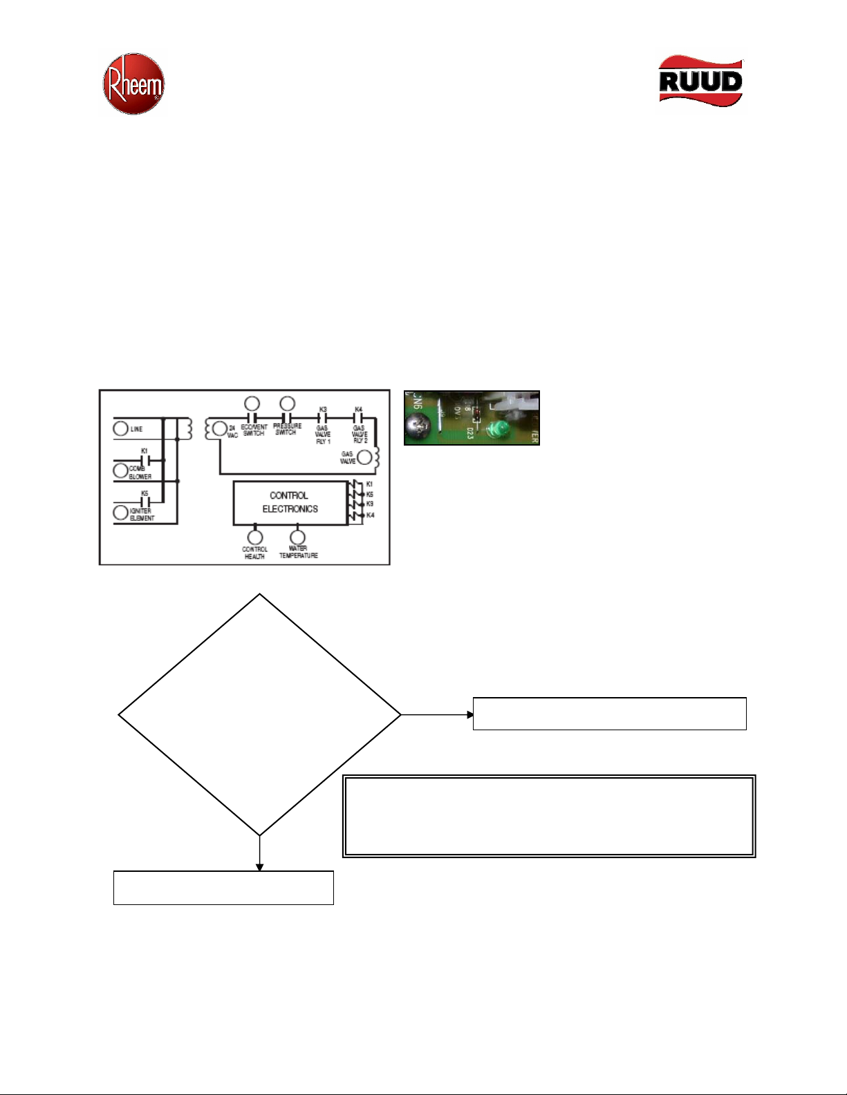
GAS VALVE; no flame rectification; maximum ignition attempts.
Explanation: The LED is ON when power is applied to
the gas valve. Controls are looking for flame
rectification, meaning there is main burner. Unit will
make three successive trials; then lock out
At a minimum check the following:
1. Gas valve shut OFF
2. Broken or corroded flame sensor wire
3. Connectors on control panel unplugged
4. Tubing between valve and air inlet is present
5. Unit has proper service pressure
6. Gas fuel supply or piping problem
7. Gas valve improperly adjusted
8. Verify green polarity light on board
AdvantagePlus Fault Tree Troubleshooting
1706.doc
9
Gas Supply Related Questions:
1. What is the Utility Co. meter capacity compared to the total connected gas load?
a. Must be of adequate capacity to handle total load. This includes meter and meter regulator serving
building gas distribution.
2. Is the service a 5 pound, 2 pound, or inches WC service?
a. If the service is a 7" WC service, it is most unlikely there will be 7" WC operating gas pressure at
the unit.
3. Is there an in-line appliance regulator serving the AdvantagePlus?
a. How far up stream is the in-line appliance regulator from the AdvantagePlus?
Continue to next step
Is the gas valve
operating
properly?
Yes
No Replace control board
1. Recycle power to the heater. When the “GAS VALVE” LED is
ON, measure 24 VAC between the yellow and blue wires of
CN6. This is the power to the gas valve.
2. If you get less than 24 VAC, then disconnect the low water cut-
off. Jumper the two green wires.
3. Recycle power. If the main burner comes on, replace the low
water cut off switch. If the unit does not come on, continue to
next step.
Continue with Gas Supply Related Questions
Is the gas
p
ressure and fuel
supply OK?
Yes
No Repair as needed
Gas pressure (natural) between 7” and 14” w. c.
during firing cycle. If inlet pressure drops below
7” during burner operation, the gas supply piping,
regulator(s), meter, or LP tank, etc. is undersized.
AdvantagePlus Fault Tree Troubleshooting
1706.doc
10
b. What size is the pipe between the appliance regulator and the AdvantagePlus ¾ inch x ½ inch
factory installed reducing coupling?
c. Most of the time these regulators are installed too close to the unit. They must be upstream 10',
and minimum 3/4" ID black steel pipe run all the way to the 3/4" x 1/2" factory installed reducing
coupling. No flex connectors allowed, except a Dormont 3/4" ID commercial grade connector.
d. What is the BTU capacity of the in-line appliance regulator?
4. The gas supply regulator must be of sufficient size to accommodate all gas products it will service. If you
have two 100,000 BTU heaters, then the regulator must be capable of supplying a minimum of 200,000 BTUs of
fuel.
5. Is the in-line regulator vented to the atmosphere?
a. If not, is the regulator equipped with a "vent limiter"?
b. In our experience some regulators are prone to field problems with inconsistent regulator
performance. They have vent-limiting devices, and do not respond well.
6. Verify the gas orifice is installed, and it is the correct orifice for the gas in use.
7. Is there a fabricated drip leg to keep debris out of the gas valve?
Adjust the AdvantagePlus using a CO meter. CO above 10 parts per million will cause premature igniter failure,
premature burner failure, and huffing and puffing sounds.
Many installations on natural gas are victims of insufficient gas volume due to inadequate gas available on the
job. Meter sizing, and building distribution piping, more often than not, is the culprit. In addition, CSST
(Corrugated Stainless Steel Tubing) is a major problem! This material may be used only on 2-pound systems to
supply high-pressure gas to the appliance regulator, assuming it is properly sized for the job. The low-pressure
gas from the regulator to the AdvantagePlus must be 10 feet of 3/4" ID black steel pipe.
Igniter; Power to igniter
Explanation: Monitors igniter element output. The
LED is ON when 120VAC power is applied to the
igniter.
At a minimum, check the following:
1. Igniter current draw is too low.
2. Molex is connected.
Does the igniter have
voltage?
Yes
No
Replace control board
Measure for 120 VAC at CN5.