Which is correct?
To determine the fan’s actual rotational speed, one of the
ventilator vanes is attached with a marking and the test is
repeated.
Image No. 1 2 3 4
Flashing rate 3,300 2,200 1,650 1,320
Image No. 5 6 7 8
Flashing rate 1,100 825 733.3 550
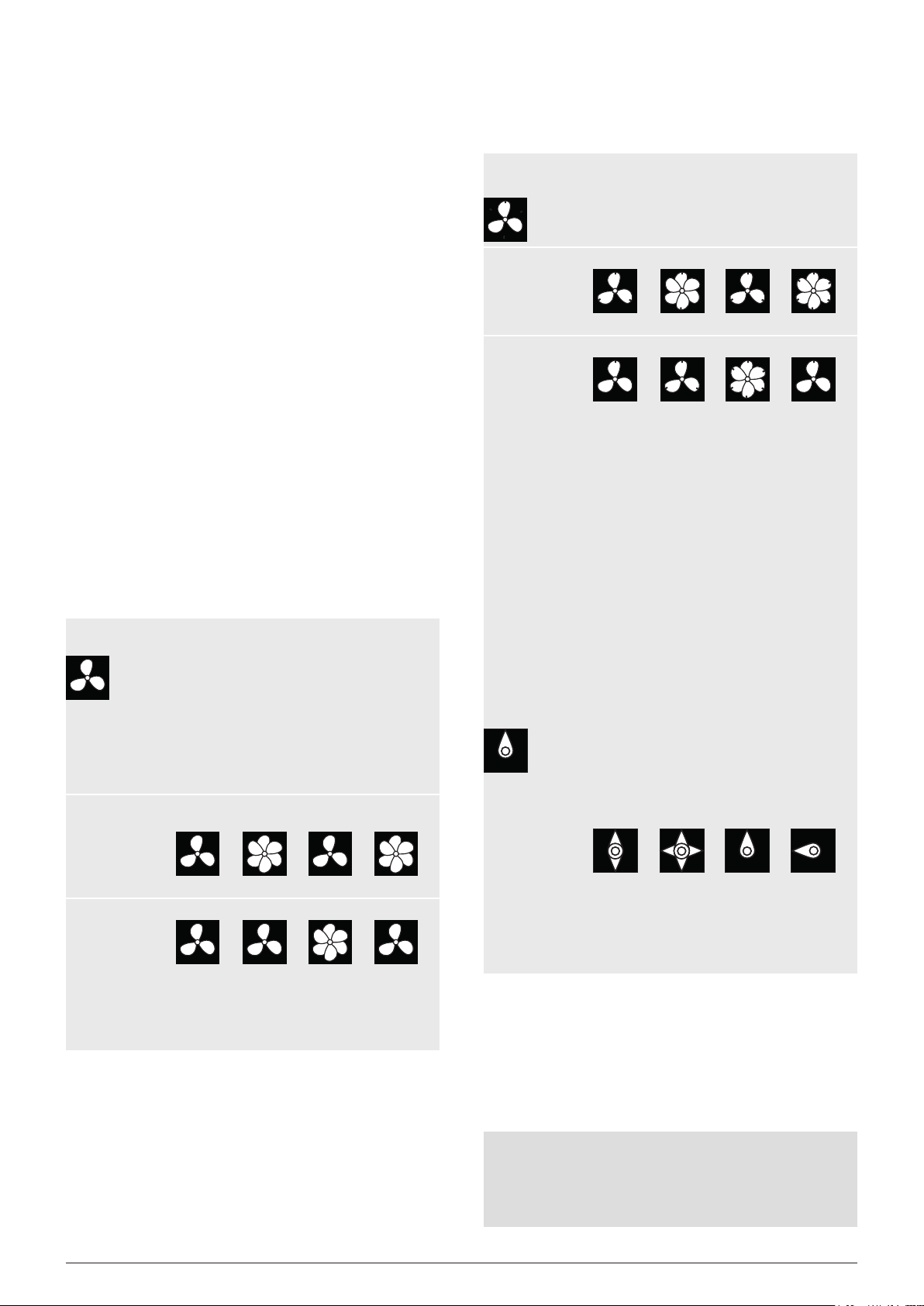
The orientation marking conrms that the images at 3,300, 1,650 and
825 rpm are harmonic multiple images. Three identication marks
appear in each of these images.
Still images appear at 1,100 rpm and again 550 rpm, each displaying
just one mark. Remember that a still image always appears exactly
at integer division of the speed of the actual rotational speed of an
object. 550 is half of 1,100. This means that the rotational speed of
the ventilator must be 1,100 rpm.
Example 2 (no marking required):
This example shows how the actual rotational speed of an object
can be determined without using an orientation marking. This is only
possible for suitably shaped objects.
Let’s assume the only thing we know about this cam is that
it rotates at less than 7,000 rpm. Its clear shape eliminates
the need for an orientation marking. The following “frozen”
imageswillappeariftheashingrateof7,000isreduced:
Image No. 1 2 3 4
Flashing rate 6,000 4,000 3,000 1,500
The images showing 6,000 and 4,000 rpm are double or multiple
images rather than single images. Still images appear at 3,000 and
again at 1,500 rpm. 1,500 is half of 3,000. This means that the actual
rotational speed is 3,000 rpm.
Printed CE declaration of conformity is available on request.
Subjecttotechnicalchangeswithoutpriornotication.Although
the content of these instructions was compiled with the greatest
care, we cannot accept liability for any errors.
10 Operating instructions RT STROBE qbLED / RT STROBE qbLEDs / RT STROBE super qbLED
▪
▪
▪
8. Accessories, optional
DIN plug 5-pin, edge bumpers, mounting kit for tripod or articulating
arm, articulating arm including mounting kit, tripod, connection cable
(1.5 m), extension cable (2.0 m), trigger sensors
9. Determining the actual rotational speed
of an object
The stroboscope can be used as a digital revolution indicator to deter-
mine an object’s actual rotational speed and/or the frequency of cyc-
lical movements. The stroboscope does this by visually “freezing” the
object’s movement and then taking a reading of the rotational speed or
frequency from the LCD display. As is the case with all stroboscopes,
it is vital to ensure that this “frozen” image is not a harmonic of the
object’s actual rotational speed.
Useful information:
It’s helpful to have a rough idea of the object’s rotational speed
beforehand.
Regular shaped objects, e.g. a fan with several vanes or a motor
shaft,mustbeaxedwithanidenticationmarking(usingcolour
orareectivestripetc.)inordertobeabletodierentiateits
orientation of movement.
A still image always appears exactly at integer division of the
speed of the object’s actual rotational speed!
Example 1 (marking required):
Thisexampleshowstheimportanceofusingidentication
markings. Say you want to determine the actual rotational
speed of this ventilator.
The only thing you know is that its rotational speed is less
than 3,500 rpm. The following “frozen” images will appear if
youreducetheashingratebasedon3,500FPM(ashes
per minute):
Image No. 1 2 3 4
Flashing rate 3,300 2,200 1,650 1,320
Image No. 5 6 7 8
Flashing rate 1,100 825 733.3 550
What is the actual rotational speed of the fan? Images 1, 3, 5, 6 and
8 correspond to the original one, which means the rotational speed
could be 3,300, 1,650, 1,100, 825 or 550 rpm.