RHEINTACHO RT STROBE pocketLED LASER User manual

(A) ON / OFF
(B) Menu
(C) Laser/Conrmationbutton
(D) MINUS
(E) PLUS
(F) DIV(Divider)
(G) MUL(Multiplier)
(H) Triggerconnection
(1) Brightnessinμsand/ordegrees(BRIGHT)
(2) Delayinms(DELAY)
(3) Phaseshift(PHASE)
(4) Lasersymbol
(5) Unitoffrequencyin1/min,Hzand/orFPM
(6) Value
(7) Mode(STROBO/TACHO)
(8) Triggerdivider(DIV.)
(9) Slowmotion(SLOW)
(10) Triggersignaledge(TRIG.)
(11) Internal/externaltrigger(INT/EXT)
(12) Store/readparameter
(MEMORYIN/MEMORYOUT)
(13) Statistics(average/min/max)
(14) Proselection(P)
(15) Batterystatus–full,halffull
Figure 2: Display
(1) (2) (3)
(4) (5)
(6)
(7) (8)
(9) (10)
(11) (12)
(13) (14)
(15)
1. Complete overview of connections,
controls and settings
2Operating instructions RTSTROBEpocketLEDLASER
STROBO
TACHO
average
min
max
Figure 1: Stroboscope RT STROBE pocketLED LASER
(A)
(E)
(G)
(D)
(F)
(B)
(C) M
+
*
-
÷
I
L
(H)

1 Completeoverviewofconnections,controlsandsettings 2
2 Technicaldata 4
3. Abouttheseoperatinginstructions 5
3.1 Conventionalrepresentationinthisdocument 5
3.1.1 Presentationofworkinstructions 5
4 Intendeduse 5
5 Scopeofdelivery 5
6 Gettingstarted 6
6.1 Briefdescriptionofset-upsteps 6
6.2 Additionaloperatinginstructionsfortheversionwithtriggerconnection 6
7 Operation 6
7.1 Buttonassignment 6
7.2 Display 7
7.2.1 Overviewofadjustableparameters 7
7.2.2 Standardselection 7
7.2.3 Proselection 8
7.2.4 LASERintheTACHOandSTROBOmode 9
7.2.4.1 Useofthelaser 9
7.2.4.2 Auto-Syncfunction 9
7.2.4.3 Auto-Savefunction 9
7.2.5 Operationmode 10
7.3 Factoryreset 10
8 Accessories,optional 11
9 Determiningtheactualrotationalspeedofanobject 11
Contents
3
Operating instructions RTSTROBEpocketLEDLASER

4Operating instructions RTSTROBEpocketLEDLASER
2. Technical data
General parameters
NumberofLEDs 6
Frequencyrange 30…999.999FPM(Flashesperminute)
Display LCD,multiline,coloredlighting
Accuracy Flashfrequency(internal)andfrequencymeasurement(external):
±0.02%(±1digit/±0.025µs)
Resolution ±0.1(30.0...999.9FPM)
±1(1,000...999.999FPM)
Currentconsumption Max.1.2A
Flash parameters
Lightduration 0.025°…6.000°/1…1,000µs
Lightintensity 6,500Lux@300mm(12inch)/9,000Lux@200mm(8inch)
Flashcolor approx.6,500K(5,000…8,000K)
Illuminationarea approx.80mm@300mm
approx.3inch@12inch
Power supply
Powersupply 3xAAsizedisposablebatteriesor
3xNiMHrechargeablebatteries
Continuoususetime 5h@6,000FPM
Housing
Material Aluminium/ABS,Heavydutydesign
Dimensions(device) 191x82x60mm
Dimensions(case) 207x252x72mm
Weight(device) approx.400g(includingbatteries)
Weight(total) approx.930g(includingcase)
Ambient conditions
Temperature 0...45°C/32...113°F
Typeofprotection IP65
AdditionalinformationforRTSTROBEpocketLEDLASERwithtriggerinputandoutput.
Trigger input
Inputsignallevel Max.power:3…30V
Lowlevel:<2.0V
Highlevel:>3.0V
Pulselength:>50µs
Switch:internal:10kOhmto+24V
Inputcurrent 10kOhmto+24V
Trigger output
Outputsignallevel Short-circuitandovervoltageprooftransistoroutput,
non-isolatedNPN,<1V,max.30V
Outputcurrentcapability max.50mA
Sensorsupply 24VDC±15%max.60mA

3. About these operating instrucions
Theseoperatinginstructionsareanintegralpartofthedevice.They
mustbestoredinaneasilyaccessiblelocation andpassedonto
subsequentusers.Askyoursupplierifthereis somethingyoudo
notunderstand.
Read the operating instructions thoroughly and follow the
instructions provided. These operating instructions contain
important information about installing, commissioning
and operating the stroboscope. Pay particular attention
to the safety information and warnings to prevent injuries
and product damage.
Themanufacturerreservestherighttodevelopandupdatethe
productcontinuously,withoutdocumentingalldevelopments.Your
supplierwillbepleasedtoprovideinformationonthestatusofexis-
tingoperatinginstructionsandonanyalterationsandextensions
thatmayberelevant.
3.1 Conventional representation in this document
3.1.1 Presentation of work instructions
Workinstructionsareshowninnumberedstepsandmustbecarried
outintheorderstated.
1. Step
→Anarrowisusedtoshowstroboscopereactionstoastep.
2. Step
3. Step
Theendofaworkinstructionisshownasfollows:
þEndofworkinstruction
Aworkinstructionthatonlyconsistsofonesinglestepwillappear
asfollows:
►Step
4. Intended use
Thisdevice isusedforinspectingthemovementof rotatingand
vibratingobjects(STROBOmode)andfornon-contactmeasurement
ofrotationalmovements(TACHOmode).Itmayonlybeused in
accordancewiththeseinstructions.Thedevicemustnotbeopened.
Modicationstothedevicearenotpermitted.Themanufacturershall
notbeliablefordamageresultingfromincorrectuseorusecontraryto
theintendeduse.Warrantyclaimswillalsobeinvalidatedinthisevent.
Warning
Risk of injury!
Moving objects appear still or in slow motion in stroboscopic light.
Do not touch such objects under any circumstance.
Warning
Risk of injury!
The device may not be used in potentially explosive areas.
Warning
Risk of injury!
Stroboscopic light can trigger epileptic seizures in persons at risk.
Warning
Risk of injury!
NeverdirecttheLEDbeamatpeopleoranimalsanddonotstare
directlyatthebeam.
Warning
Risk of injury!
Laserclass2
Thestroboscopeisttedwithaclass2laser.Thisislocatedatthe
LEDarrayofthisdevice.Thelaserbeamcandamageeyes.
Forthisreason,donotstaredirectlyatthelaserbeamandnever
directitatpeopleoranimals.Wavelength:650nm,output:1mW
Caution
Flashing lights can cause retina damage!
Thestroboscopeisttedwith6LEDs.Theseproduce
potentiallydangerousopticalradiation,whichcancause
retinadamage.Donotstaredirectlyatthelightandnever
directitatpeopleoranimals.
Caution
Warranty void!
Thedevicemayonlyberepairedbythemanufacturerorbyan
authorizedsupplier.
Caution
Correct disposal!
Theelectroniccomponentsinthedevicecontain
environmentallyharmfulsubstances.Theymustbe
disposedofinaccordancewiththeenvironmental
regulationsinthecountryofuse.
Note
Suitableforuseinresidential,commercialandindustrialarea.
Note
Lowrisk(Riskgroup1–RG1)
ThebrightnessoftheLEDscorrespondtotheriskgroup1
accordingtoDINEN62471:2009-03.Thelampresp.thelight
representsnohazardfortheuserundernormalbehavioral
limitations.
5. Scope of delivery
Checkthatyouhavereceivedallofthefollowing:
▪ StroboscopeRTSTROBEpocketLEDLASER(deviceversion
withtrigger/deviceversionwithouttrigger)
▪ Operatinginstructions
▪ Calibrationcertificate
▪ Cablewithplugfortriggersignal(deviceversionwithtrigger)
▪ Reflectivetapes
▪ 6xAAsizedisposalbatteries
▪ Case
5
Operating instructions RTSTROBEpocketLEDLASER

6. Getting started
6.1 Brief description of set-up steps
Pleasefollowthestepsbelowwhensettingupthedevice:
1.Place3AAsizebatteriesorNiMHrechargeablebatteriesinto
thedevice.
2.Directthedeviceatamovingobjectandswitchon.Press
thebutton“ON/OFF”(A)foratleast1second.
The device will start to ash straightaway. For this reason,
do not direct it at people or animals.
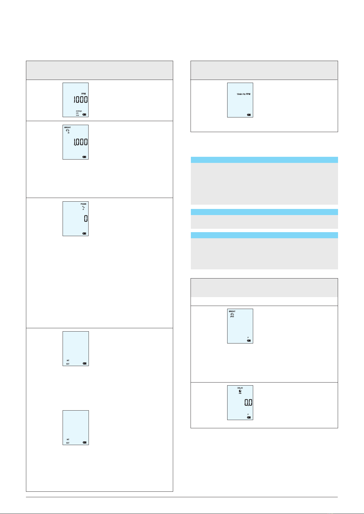
• Thedevicewillflashatthefrequencythatwassetmostrecently.
Thedisplayshowstheselectedflashfrequencyintheunitthat
wassetmostrecently(1/min,HzorFPM).
▪ Iftheflashfrequencycoincideswiththefrequencyofthemotion,
astaticimageappears.
▪ Ifnecessary,resettofactorysettingbypressingandholdingthe
buttonsMenu“M”(B)and“MINUS”(D)simultaneously.
Note
Static images are produced when the ash frequency is identical
to, or a multiple or fraction of the frequency of the motion (see also
section 9 “Determining the actual rotational speed of an object”).
6.2 Additional operating instructions for the version with
trigger connection
Caution
Do not use signals over 999,999 FPM Hz to trigger the device.
Note
The device must be switched manually between external and
internal trigger signal. Thus the 24 V sensor supply is switched on.
Terminal connection assignment trigger jack (Figure 3)
Caution
Please observe the terminal connections shown in the terminal
connection diagram (gure 3).
ThetriggerinputissuitableforNPNsignals.Acablewithplug,
correspondingtotheseinputjacks,isprovidedwiththedevice.The
triggerjackislocatedatthelowerpartinthecenterofthedevice.
Figure 3: Terminal connection assignment
Note
The device must be manually switched between external and
internal trigger signals (see section 7.2.2 “Standard selection” /
How to select an internal / external trigger).
7. Operation
Note
Please note that this device comes in two versions.
Version 1: Stroboscope pocketLED LASER without trigger
Version 2: Stroboscope pocketLED LASER with trigger
Both versions are available in standard and pro modes (see
sections 7.2.2 “Standard selection” and 7.2.3 “Pro selection”).
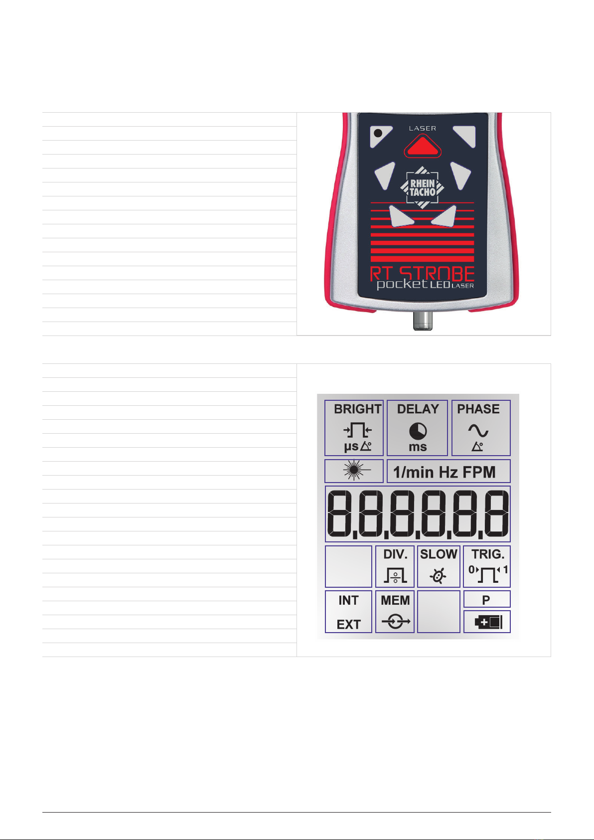
7.1 Button assignment (Figure 1 on page 2)
No. Button Description
(A) ON / OFF
(B) Menu
(C) Laser
(D) MINUS
(E) PLUS
(F) DIV
(G) MUL
Note
The symbol of a parameter that differs from the factory settings will
ash during operation.
6Operating instructions RTSTROBEpocketLEDLASER
-Switchonthedevicebypressingthebutton
foratleast1second.
-Pressthisbuttontoswitchbetweenthe
differentsettingsandoperationmodes
inthesequenceofthedisplayindicator
(seegure2).
-Pressthisbuttontoactivatethelaser.
-Thelaserisactivatedandmeasuresthe
frequencyaslongasthebuttonispressed.
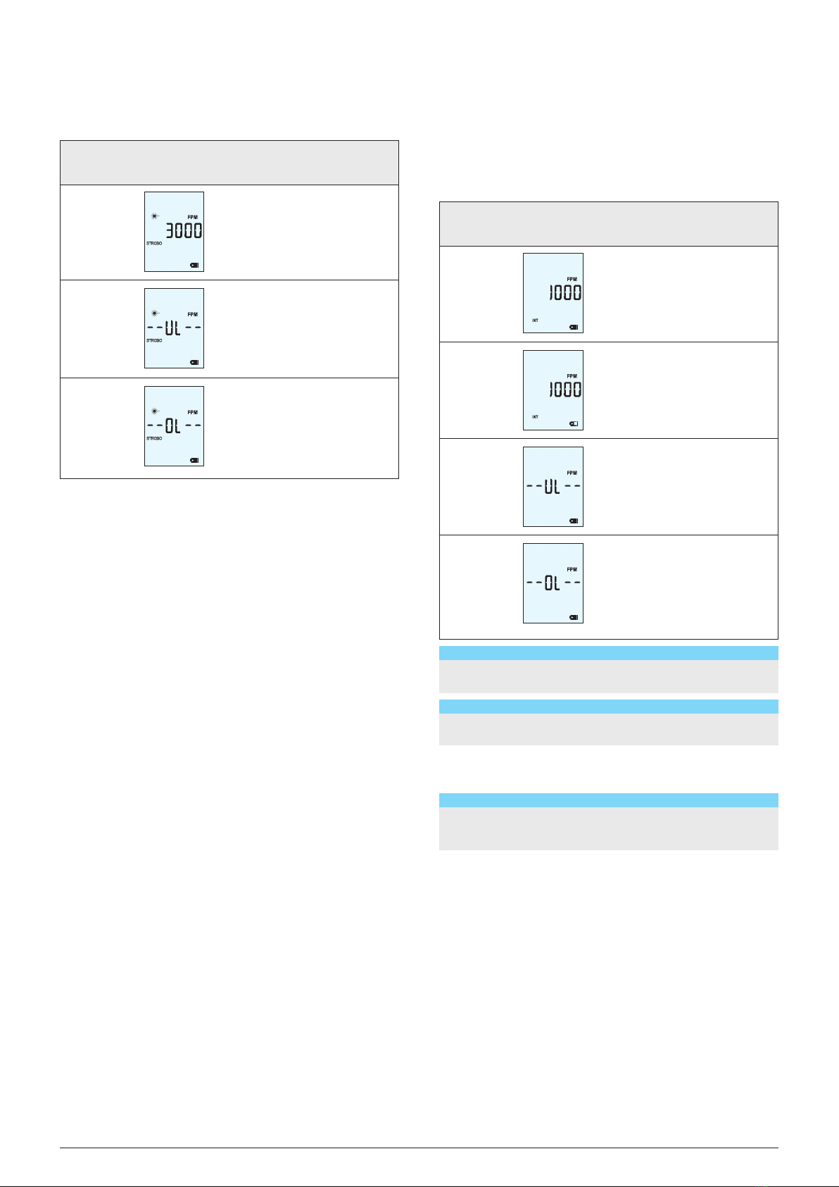
>>IntheSTROBOmode:Thedeviceashes
uponrecognitionofthereectivetape.
>>Theminimum,maximumandaverage
valuesaredetermined(min,max,
average).
>>Ifthemeasuredvalueremainswithina
toleranceof±5%for2seconds,
thisvalueistakenoverasanewash
frequencyafterreleasingthebutton.
-Momentarilypressthebuttontoactivate.
Thelaserremainsactivateduntilthebuttonis
pressedagain.
-Thisbuttoncanalsobeusedtoconrm
selectedsettings.
-Decreasesthecurrentlyselectedvalue.
>>Accelerateswhenthisbuttonispressed.
-Switchbetweenthevarioussettings.
-Increasesthecurrentlyselectedvalue.
>>Accelerateswhenthisbuttonispressed.
-Switchbetweenthevarioussettings.
-Halvesthecurrentlyselectedvalue.
>>Accelerateswhenthisbuttonispressed.
-Doublesthecurrentlyselectedvalue.
>>Accelerateswhenthisbuttonispressed.

7.2 Display
Note
Preset values are retained in each mode (standard or pro
selection)!
7.2.1 Overview of adjustable parameters
Note
Backlight changes depending on selected mode.
STROBO mode: white
TACHO mode: orange
Laser mode: light-blue
When inactive, the backlight turns off automatically after approx.
10 seconds.
7.2.2 Standard selection (Figure 2 on page 2)
Note
Not all of the settings shown in gure 2 are available in standard
selection.
7
Operating instructions RTSTROBEpocketLEDLASER
Set frequency
Select mode
Statistics
Set brightness
Set phase shift
Select trigger
Select frequency unit
Select brightness unit
Set delay
Set trigger divider
Set slow motion
Set trigger signal edge
Store parameter
Read parameter
Display
1/min / Hz / FPM
STROBO / TACHO
min / max / average
BRIGHT deg
PHASE deg
INT / EXT
1/min / Hz / FPM
BRIGHT deg / µs
DELAY ms
DIV.
SLOW
TRIG.
MEM in
MEM out
Standard
•
•
•
•
•
•
•
Without
Trigger
•
•
•
•
•
•
•
•
•
•
Pro
•
•
•
•
•
•
•
•
•
•
•
•
•
•
With
Trigger
•
•
•
•
•
•
•
•
•
•
•
•
•
•
TACHO
•
•
•
•
STROBO Device
Set
value
•
•
•
•
•
•
•
•
Select
parameter
•
•
•
•
•
Functions of button Menu “M” (B)
No.
(7)
No.
(7)
Off
Display
resp. setting the
frequency
Mode
Display
-
Display
Adjustable
parameters
Adjustable
parameters
TACHO / STROBO
Description
Device is switched off.
Display resp. setting the
frequency frequency in 1/m,
Hz or FPM.
Change the frequency by
pressing the buttons “PLUS”
(E ), “MINUS” (D), “DIV” (F)
and/or “MUL” (G).
Description
Selection of the mode:
TACHO or STROBO
How to set the frequency:
1. Switch on the device by pressing the button “ON / OFF” (A) for at least 1 second.
→Thefollowingwillthenappearinthedisplayforafewseconds
▪ allsettingsfollowedby
▪ “S”,forstandardselection
→Thefollowingwillthenappearinthedisplay:
2. Set the desired frequency by pressing the
buttons “PLUS” (E ), “MINUS” (D), “DIV” (F)
and/or “MUL” (G).
þThis setting is now active.
How to select the mode:
1. Switch on the device by pressing the button “ON / OFF” (A) for at
least 1 second.
→Thefollowingwillthenappearinthedisplayforafewseconds
▪ allsettingsfollowedby
▪ “S”,forstandardselection
→Thefollowingwillthenappearinthedisplay:
2. Press the button Menu “M” (B) to switch
between the different settings and operation
modes in the sequence of the display indica-
tor. Select the parameter you want to change
(e.g. STROBO/TACHO).
→Thefollowingwillappearinthedisplay:
→Theactiveparameterashes
3. Switch between the parameters by pressing the buttons “MINUS” (D) or
“PLUS” (E).
4. Press the button menu “M” (B) again to move to the next parameter.
þThis setting is now active.

7.2.3 Pro selection (Figure 2 on page 2)
Note
Follow the steps below to access the pro mode:
► Switch on the device by pressing the button “ON / OFF” (A)
and Menu “M” (B) simultaneously until the “Pro” notication
appears in the display.
→The following will then appear in the display: “Pro” for pro
selection.
Note
If pro mode is activated, a “P” will be shown in the bottom right
area of the display.
Note
If you have selected settings in pro selection and then switch the
device off, these settings will ONLY be active when the device
is switched back on if pro selection is activated. Otherwise, only
the standard selection settings will be active.
(3) Phase shift PHASE deg.:
0 … 359
Setting the delay between
triggersignalandash(in
degrees;positionoftheash
isxed,eventhoughthe
frequency changes).
(1) Brightness BRIGHT deg.:
0,025° ... 6,000°
Setting the brightness
(in degrees).
No.
(13)
No.
(5)
No.
(1)
(2)
Statistics
Frequency unit
Off
Brightness
Delay
Display Display
Display
-
Adjustable
parameters
Adjustable
parameters
1/min / Hz / FPM
Adjustable
parameters
BRIGHT deg / µs
DELAY ms:
0,0 … 2.000
Description
The minimum, maximum
and average values are
consecutively displayed for
3 seconds each.
Description
Selection of the frequency
unit:
- 1/min: Unit for measuring
rotational speed
- Hz: Flash frequency per
second
- FPM: Flashes per minute
Description
Device is switched off.
Selection of the brightness
unit (in degrees or in micro-
seconds).
BRIGHT deg: 0.025° … 6.000°
BRIGHT µs: 1 … 1,000 µs
Setting the delay time (in
milliseconds) between the
triggersignalandash
(positionoftheashchanges
withchanging/uctuating
frequency).
(11) Trigger INT / EXT Selection of the trigger:
Internal or external
- This function is only
available with the device
version with trigger.
8Operating instructions RTSTROBEpocketLEDLASER
Brightness (BRIGHT in deg)
Flashduration.Thisfunctionallowstheashdurationtobeadjusted,whichinuences
thebrightnessandfocusoftheobjectbeingviewed.Inthestandardmode,thissetting
can only be made in relative form (degrees), whereas the pro mode also features
the additional setting of measuring brightness in absolute form (microsenconds).
Phase shift (PHASE in deg)
Phase shift setting (in degrees, relative to the frequency) between the trigger
signalandash.Thisvalueallowsaxedangletobesetbetweenthetrigger
signalandash.
▪Example without external connection: The viewing position can be extremely
preciselyadjustedwithoutchangingtheflashfrequency.Youcanshifttheviewing
position within a movement cycle.
▪Examplewithexternalconnection:Theexternaltriggersignalistriggeredbefo-
re the desired observation point (= flash position of the stroboscope). This would
mean that the connected stroboscope would regularly flash too early. The PHASE
degsettingadjuststhedelay,alteringtheflashpositionofthestroboscopebya
set angle. This setting is not affected by the current rotational speed, which means
that the stroboscope will flash at the desired position even during rotational speed
fluctuations or during the start-up period.
How to select the trigger:
1. Switch on the device by pressing the button “ON / OFF“ (A) for at least 1 second.
2. Press the button Menu “M” (B) to switch between the different settings
and operation modes in the sequence of the display indicator. Select the parameter
INT / EXT.
→Thefollowingwillappearinthedisplay:
→Theactiveparameterashes
3. Switch between the parameters by pressing the buttons “MINUS” (D) or
“PLUS” (E).
4. Press the button menu “M” (B) again to move to the next parameter.
þThis setting is now active.
Brightness (BRIGHT in deg / BRIGHT in µs)
Flashduration.Thisfunctionallowstheashdurationtobeadjusted,whichinu-
encesthebrightnessandfocusoftheobjectbeingviewed.Brightnesscaneither
be measured in absolute terms (microseconds) or in relative terms (degrees).

7.2.4 LASER in the TACHO and STROBO mode
Warning!
Risk of injury!!
Laser class 2
The stroboscope is tted with a class 2 laser. This is located at
the LED array of this device. The laser beam can damage
eyes. For this reason, do not stare directly at the laser beam
and neverdirect it at people or animals. Wavelength: 650 nm,
output: 1 mW.
Bymeansofareectivelaserbeam,thisstroboscopeoffersthe
possibility todeterminetheashratealmostautomaticallyand
thusletmovingpartsappearoptically“frozen”.
Ifyouonlywanttomeasuretherevolutions,youcanalsousethe
stroboscopeasalasertachometerwithdisabledashfunction.
7.2.4.1 Use of the laser
Thestroboscopefeaturesalaserinadditiontotheaforementioned
settings(seesections7.2.2“Standardselection“and7.2.3“Pro
selection“).Tousethelaser,youmustrstafxareectivetape
(includedinthescopeofdelivery)ontotheobjecttobemeasured.
Pressthebutton“Laser”(C)toactivatethelaseranddirectthe
stroboscopeatthereectivetapeontotherotatingobject.
Thelaserbeamwillbereectedbythisreectivetapebacktothe
receivingcellonthefrontsideofthestroboscope.
Asaresult,thecontrolofthestroboscopecalculatestherotation
rateoftheobject.
7.2.4.2 Auto-Sync function
Thisfunctionallowsforthesynchronisationfrequencytobedeter-
minedveryquickly,withoutmanualadjustmentorexternalsensor
signals.Furthermore,theadditionallygeneratedvalueguarantees
absolutemeasuringcertainty.
7.2.4.3 Auto-Save function
Toenabletheintegrated“Auto-Save“feature,directthestrobo-
scopeattherotatingobjectforatleast2seconds.Themeasured
frequencywillbestored.Afterreleasingthebutton“Laser“(C),
thestroboscopeashesatthisfrequencyanditcannowbeused
forallothersettings.
Note
The stroboscope function is disabled in the TACHO mode
(LEDs off). In the TACHO mode, the backlight in the display
changes to orange.
Momentarilypressthebutton“Laser“(C)toactivate.Thelaser
remainsactivateduntilthebuttonispressedagain.
Note
By activating the laser, the laser symbol appears in the display
and the backlight changes to light-blue. When the reective tape
is detected at low speed, the laser symbol ashes briey. At higher
speed, it will ash continuously.
No.
(8)
(9)
(10)
(12)
(12)
Trigger divider
Slow motion
Trigger signal
edge
Store parameter
Read parameter
Display Adjustable
parameters
DIV:
1 … 65,535
SLOW:
0 … 600 FPM
TRIG.
0 / 1
MEM IN:
1 … 5
MEM OUT:
1 … 5
Description
Trigger divider,
max. value 65,535.
- This function is only possible
when the external trigger is
selected.
-Theashfrequency
0 … 600 FPM exceeds the
trigger by the value selected.
- This function is only possible
when the external trigger is
selected.
Setting the trigger signal edge
(increasing: 0, decreasing: 1).
- This function is only possible
when the external trigger is
selected.
Selected parameters can be
backedupinveseparate
storage locations.
Set the desired storage loca-
tion by pressing the buttons
“PLUS” (E) or “MINUS” (D).
-Conrmthesettingbypres-
sing the button “Laser” (C).
Stored parameters can be
read out.
- Set the desired storage
location by pressing the but-
tons “PLUS” (E) or
“MINUS” (D).
-Conrmthesettingbypres-
sing the button “Laser” (C).
Operating instructions RTSTROBEpocketLEDLASER
Trigger divider (DIV)
The trigger divider can be used to set a value x, by which the external trigger
signal is then divided.
Example: when scanning a cog wheel, an external trigger (e.g. rotational speed
sensor) sends out a signal for each cog scanned. With a DIV value of 10, it will
onlyashonceinevery10signals.
SLOW (slow motion)
The “SLOW” function allows the viewer to view movement in slow motion. The
speedoftheslowmotiondependsontheashfrequencyandcorrespondstothe
value selected.
9

10 Operating instructions RTSTROBEpocketLEDLASER
7.2.5 Operation mode
Thefollowingoperationmodesmaybedisplayed:
Note
When inactive, the backlight turns off automatically after
approx. 10 seconds.
Note
The stroboscope will be automatically switched off after
15 minutes.
7.3 Factory reset
Note
To reset the factory settings, press and hold the buttons Menu “M”
(B) and “MINUS” (D) simultaneously.
No.
Battery status
Battery status
LASER / EXT
LASER / EXT
Display Adjustable
parameters
Description
Battery fully charged.
Battery half charged.
The trigger frequency
is below the measurement
range.
The trigger frequency
is below the measurement
range.
No. Display Adjustable
parameters
Description
The trigger frequency is
3,000ashesperminute,
determinedbythereective
laser beam. Das The laser
symbolashes.
The trigger frequency
is below the
measurement range.
The trigger frequency
is above the
measurement range.

Operating instructions RTSTROBEpocketLEDLASER 11
8. Accessories, optional
▪Beltbagwithclip
▪Mountingkitfortripodorarticulatingarm
▪Articulatingarmincludingmountingkit
▪Tripod,3-wayadjustable
▪Recalibration
▪Triggercable
9. Determining the actual rotational speed of
an object
Thestroboscopecanbeusedasadigitalrevolutionindicatortode-
terminean object’sactualrotational speedand/or thefrequencyof
cyclicalmovements.Thestroboscopedoesthisbyvisually“freezing”
theobject’smovementandthentakingareadingofthe rotational
speedorfrequencyfromtheLCDdisplay.Asisthecasewithallstro-
boscopes,itisvitaltoensurethatthis“frozen”imageisnotaharmonic
oftheobject’sactualrotationalspeed.
Usefulinformation:
▪ It’shelpfultohavearoughideaoftheobject’srotationalspeed
beforehand.
▪ Regularshapedobjects,e.g.afanwithseveralvanesoramotor
shaft,mustbeafxedwithanidenticationmarking(usingcolor
orareectivestripetc.)inordertobeabletodifferentiateits
orientationofmovement.
▪ Astillimagealwaysappearsexactlyatintegerdivisionofthe
speedoftheobject’sactualrotationalspeed!
Example 1 (marking required):
Thisexampleshowstheimportanceofusingidentication
markings.Sayyouwanttodeterminetheactualrotational
speedofthisventilator.
Theonlythingyouknowisthatitsrotationalspeedisless
than3,500rpm.Thefollowing“frozen”imageswillappear
ifyoureducetheashingratebasedon3,500FPM(a-
shesperminute):
Image no. 1 2 3 4
Flashing rate 3,300 2,200 1,650 1,320
Image no. 5 6 7 8
Flashing rate 1,100 825 733.3 550
What is the actual rotational speed of the fan? Images 1, 3, 5, 6
and 8 correspond to the original one, which means the rotational
speed could be 3,300, 1,650, 1,100, 825 or 550 rpm.
Which is correct?
Todeterminethefan’sactualrotationalspeed,oneofthe
ventilatorvanesisattachedwithamarkingandthetestis
repeated.
Image no. 1 2 3 4
Flashing rate 3,300 2,200 1,650 1,320
Image no. 5 6 7 8
Flashing rate 1,100 825 733.3 550
The orientation marking conrms that the images at 3,300, 1,650
and 825 rpm are harmonic multiple images. Three identication
marks appear in each of these images.
Still images appear at 1,100 rpm and again 550 rpm, each display-
ing just one mark. Remember that a still image always appears ex-
actly at integer division of the speed of the actual rotational speed
of an object. 550 is half of 1,100. This means that the rotational
speed of the ventilator must be 1,100 rpm.
Example 2 (no marking required):
Thisexampleshowshowtheactualrotationalspeedofanobject
canbedeterminedwithoutusinganorientationmarking.Thisis
onlypossibleforsuitablyshapedobjects.
Let’sassumetheonlythingweknowaboutthiscamis
thatitrotatesatlessthan7,000rpm.Itsclearshapeelimi-
natestheneedforanorientationmarking.Thefollowing
“frozen”imageswillappeariftheashingrateof7,000is
reduced:
Image no. 1 2 3 4
Flashing rate 6,000 4,000 3,000 1,500
The images showing 6,000 and 4,000 rpm are double or multiple
images rather than single images. Still images appear at 3,000
and again at 1,500 rpm. 1,500 is half of 3,000. This means that the
actual rotational speed is 3,000 rpm.
PrintedCEdeclarationofconformityisavailableonrequest.
Subjecttotechnicalchangeswithoutpriornotication.Although
thecontentoftheseinstructionswascompiledwiththegreatest
care,wecannotacceptliabilityforanyerrors.

Notes
12 Operating instructions RTSTROBEpocketLEDLASER

Subject to technical changes
P04269 – January 2014
RHEINTACHO Messtechnik GmbH
Waltershofener Straße 1
79111 Freiburg · Germany
Tel: +49 (0)761 45 13 0
Fax: +49 (0)761 44 52 74
info@rheintacho.de
www.rheintacho.de
RHEINTACHO UK LTD
Enterprise Court, Pit Lane
Micklefield
Leeds, LS25 4BU · UK
Tel: +44 (0)113 287 4411
Fax: +44 (0)113 287 4422
sales@rheintacho.co.uk
www.rheintacho.com
We reserve the right to make technical changes.
P05391A / Status August 2018
RHEINTACHO Vision Systems S.A.S.
18, Rue de la Fabrique
68530 Buhl · France
Tel: +33 (0)3 89 83 06 82
Fax: +33 (0)3 89 83 07 43
info@rheintachovisionsystems.fr
RHEINTACHO China
Lihe Building no.306, 59 Suli Road
WuZhong District
SuZhou · China
Tel: +86 (0)512 6609 4840
Fax: +86 (0)512 6561 6513
Other manuals for RT STROBE pocketLED LASER
1
Table of contents
Other RHEINTACHO Test Equipment manuals