RHINO ENHANCER User manual

Operation Instructions For
THE ENHANCER™
SPLIT SYSTEM ALARM WITH
TWO POINT ENGINE IMMOBILISATION
FOR ED, EF & EL FALCON, VPS2, VR/VS &VT COMMODORE, & TE MAGNA
(Not suitable for vehicles fitted with factory alarm ie Berlina, Calais, Statesman)
MADEINAUSTRALIA
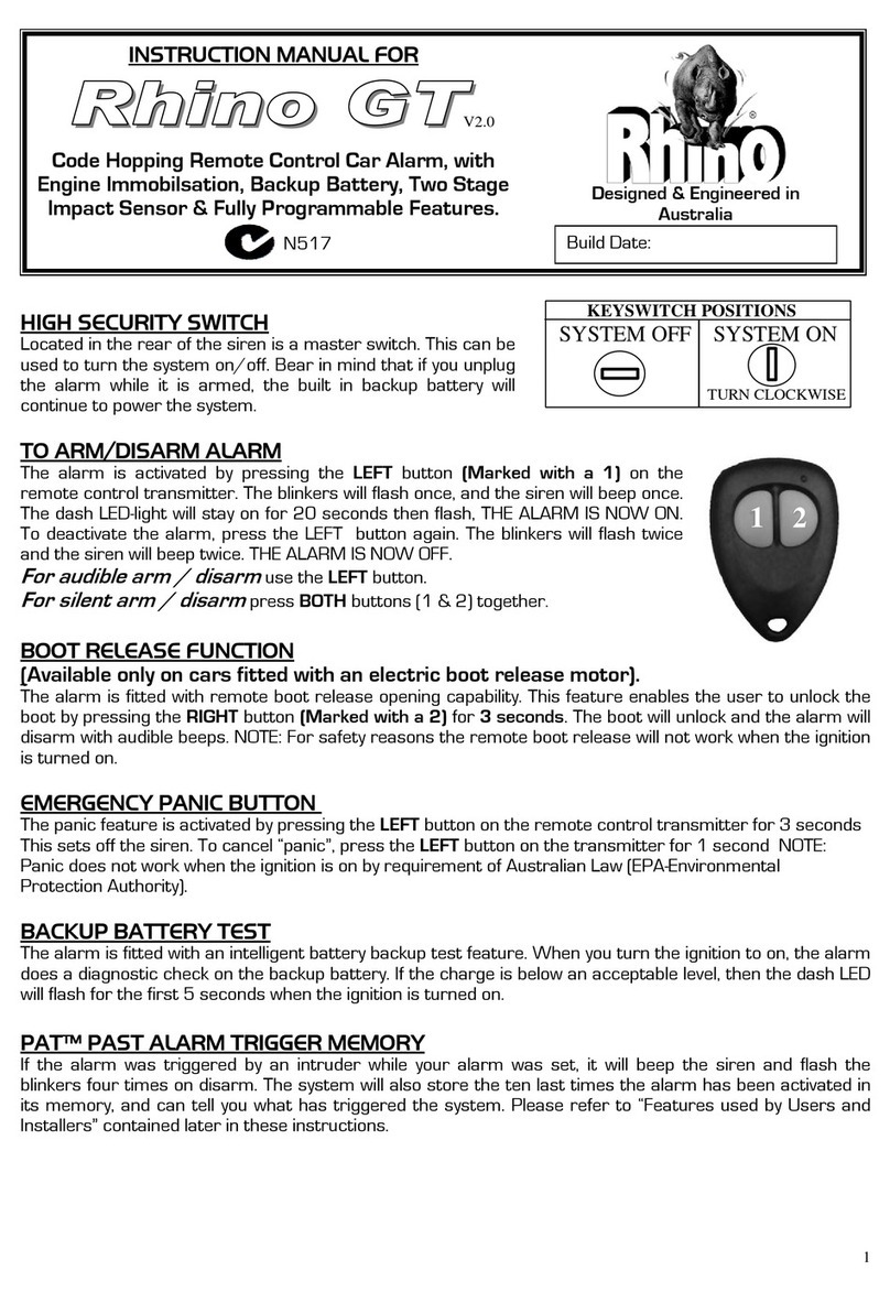
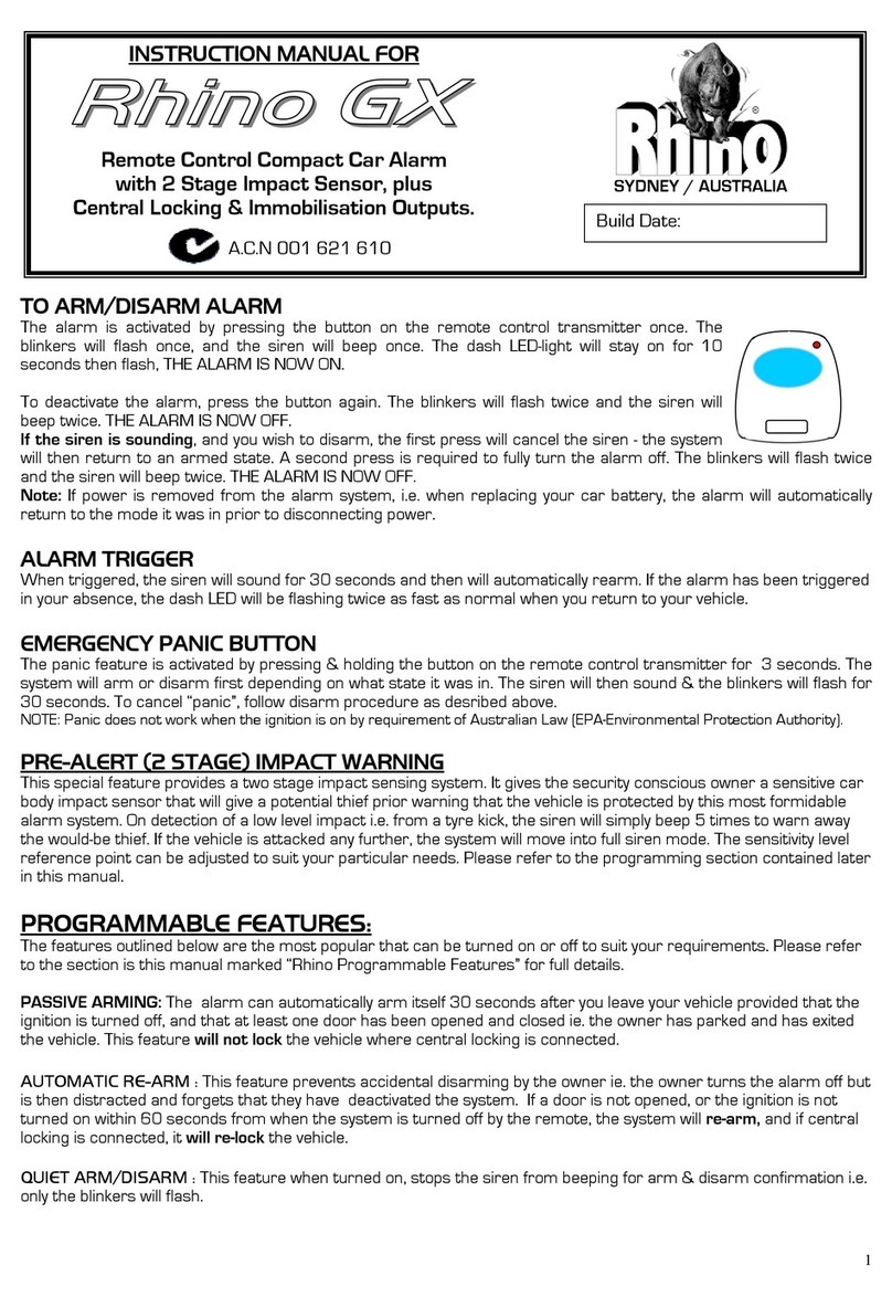
TO ARM/DISARM ALARM
The alarm is activated by pressing the button on your vehicles existing remote control transmitter. The
blinkers will flash once, and the siren will beep once, 1 second after the vehicle’s normal routine. The
dash LED-light will stay on for 20 seconds then flash, THE ALARM IS NOW ON. To deactivate the
alarm, press the button again. The blinkers will flash twice and the siren will beep twice, 1 second after
the vehicle’s normal routine. THE ALARM IS NOW OFF. Note: Allow approx. 5 seconds between
arming & disarming to allow The Enhancer to carry out full system function.
PRE-ALERT IMPACT WARNING WITH ETS™
This special feature provides a two stage impact sensing system. It gives the security conscious owner a
very sensitive impact sensor that will give a potential thief prior warning that the vehicle is protected by
this most formidable alarm system. On detection the siren will simply beep for a few seconds to warn
away the thief. If the vehicle is attacked any further the system will move into full siren mode. The
unique ETS™ Environment Tuned Sensor is able to distinguish between environmental shocks caused by
aircraft, trucks, or extreme weather conditions, and the impact caused by any thief attempting to break in
or other heavy impacts. This process allows a trouble free sensitivity that ordinary alarms simply can not
provide.
FEATURES USED BY INSTALLERS / SERVICEMEN
1. INSTALLER / SERVICE MODE:
Service mode is accessed by turning the keyswitch on the back of the SB41 siren to the off position. This
enables complete deactivation of the system without using the remote control. This is normally done
when other mechanical/electrical work is performed on the vehicle. Installer mode is accessed by the
following procedure: 1. Turn the siren keyswitch off. 2. Turn the ignition in the car on. 3. Turn the siren
keyswitch on. 4. Turn the ignition off. 5. Turn the siren keyswitch off then on. You are now in installer
mode. The installer test mode is used to quickly test and fault find; it is used to check each sector input
when door, hood, aux or voltage drop is triggered. A signal is given via the blinkers, the dash LED light
and the siren. To exit installer mode turn the ignition on then off, and then arm & disarm the system
using the remote controls.
2. PAT™ PAST ALARM TRIGGER MEMORY READ OUT VIA SIREN AND LED:
To access the PAT™ memory, open the bonnet and press the remote control once within 15 seconds, the
alarm history is then indicated via the siren and LED. The memory is cleared whenever the power is
removed from the alarm or if the keyswitch is turned to off on the SB41 siren (service mode).
1 Beep, 1 Flash - Voltage Drop Alarm 2 Beep, 2 Flashes - Not Used On This Model
3 Beep, 3 Flashes - Shock Sensor Alarm 4 Beep, 4 Flashes - Power Fail Alarm
5 Beep, 5 Flashes - Ignition Alarm 6 Beep, 6 Flashes - Aux Alarm
7 Beep, 7 Flashes - Door Alarms 8 Beep, 8 Flashes - Bonnet / Boot Alarm
If two previous alarms were caused by ie. voltage drop and shock sensor the LED will flash and the siren
will beep once for voltage drop, then no noise for 1 second then beep three times for shock sensor. The
memory will hold ten alarm memories. The last memory heard is the most recent alarm sector
triggered.

RHINO ENHANCER™ALARM SYSTEM FEATURES:
~ All Microprocessor Controlled
~ Ultra-Bright Red Flashing Light
~ Intelligent Pre-Alert Impact (Shock) Sensor with ETS™
~ Two Point Engine Immobilisation
~ Battery Backup System
~ Automatic Siren Reset Period (30 Seconds)
~ Arming and Disarming Confirmation Beep
~ Visual Arming and Disarming via Blinkers
~ Selectable Current Sensing Circuit
~ All Points of Entry Protection
~ Past Alarm Trigger PAT™Memory History Reporting Mode
~ Service and Override Mechanical Keyswitch
~ Safety Circuit Prevents Arming While Ignition On
~ World First Learning Mode for Installing the System
~ World First Poly Fuse Electronic Protection
TEACHING THE ENHANCER™TO THE VEHICLE:
FOLLOW THESE STEPS CAREFULLY.
1. Connect all wires shown in the wiring diagram except the yellow wire. (ie. Don’t
connect the ignition wire).
2. Install the siren in a position where it will be unlikely to get wet.
3. Plug the module into the loom. Please ensure that the siren keyswitch is turned to the off
position.
4. The vehicle’s existing immobiliser must be disarmed. (The vehicle should be unlocked).
5. Connect the yellow wire temporarily to +12V.
6. Turn the siren keyswitch on.
7. Arm the vehicle’s system via the remote control.
8. Wait longer than 10 seconds.
9. Then disarm the vehicle’s system via the remote control.
10.Wait longer than 10 seconds.
11.Repeat steps 7 to 10, ten (10) times.The siren will beep once to confirm completion. If
the Enhancer goes into siren mode, repeat steps 3 - 11 again.
12.Remove the yellow wire from +12V.
13.Arm the vehicle via the remotes. The Enhancer should now arm (1 Beep & 1 Flash).
14.Disarm the vehicle via the remotes. The Enhancer should now disarm (2 Beeps & 2
Flashes).
15.If the Enhancer did not arm/disarm then repeat steps 3-13, otherwise continue to step.
16.Connect the yellow wire to the vehicle’s ignition system as per wiring instructions.
WIRING INSTRUCTIONS

RED -
CONNECT TO CONSTANT +12 VOLTS VIA THE FUSE BOX AT THE POINT WHERE THE
INTERIOR LIGHT CIRCUIT IS POWERED. CURRENT (VOLTAGE) SENSING WILL NOT
WORK IF THIS PROCEDURE IS NOT FOLLOWED.
BLACK -
CONNECT TO A SUITABLE EARTH ON THE CAR BODY
ORANGE
(x2) -
CONNECT TO THE LEFT AND RIGHT INDICATOR OR PARKING LIGHT CIRCUITS
OF THE VEHICLE TO FLASH THE INDICATORS OR THE PARKING LIGHTS
YELLOW -
CONNECT TO A +12 VOLTS IGNITION SWITCHED LEAD, WHICH DOES NOT FALL TO 0
VOLT WHEN THE ENGINE IS CRANKED
DARK BLUE -
-
CONNECT TO PIN SWITCHES FOR BONNET
CONNECT TO PIN SWITCHES FOR BOOT (PLEASE NOTE: IT IS ADVISABLE TO WIRE
THE BOOT TO THE DOOR SWITCHES: THIS WILL PROVIDE “DOOR AJAR” WARNING
ON THE BOOT, AND ALSO SIGNAL THE AUTO RE-ARM FEATURE TO CANCEL IF THE
BOOT IS OPENED BY THE OWNER ON DISARMING THE SYSTEM.)
WHITE -
CONNECT TO EXISTING DOOR SWITCHES.
GREEN (X2)
Inside main loom -
LOCATE THE POSITIVE FEED WIRE TO THE STARTER SOLENOID, CUT THAT WIRE
AND JOIN THE TWO GREEN WIRES TO EITHER END OF THE STARTER FEED WIRE
WHICH YOU HAVE JUST CUT WARNING: CUT OUT RELAYS HAVE 12A MAX RATING.
DISABLE ONLY STARTER SOLENOID, FUEL PUMP, OR IGNITION COIL IF VEHICLE IS
NOT EFI. UNDER NO CIRCUMSTANCES SHOULD YOU CUT THE VEHICLE’S MAIN
IGNITION SYSTEM.
GREEN (X2)
Outside main loom -
LOCATE THE POSITIVE FEED WIRE TO THE FUEL PUMP, CUT THAT WIRE AND JOIN
THE TWO GREEN WIRES TO EITHER END OF THE FUEL PUMP FEED WIRE WHICH YOU
HAVE JUST CUT WARNING: CUT OUT RELAYS HAVE 12A MAX RATING. DISABLE
ONLY STARTER SOLENOID, FUEL PUMP, OR IGNITION COIL IF VEHICLE IS NOT EFI.
UNDER NO CIRCUMSTANCES SHOULD YOU CUT THE VEHICLE’S MAIN IGNITION
SYSTEM.
YELLOW/ BLACK -
THIS IS A SWITCHED NEGATIVE OUTPUT (-VE 150mA). CONNECT TO THE NEGATIVE
WIRE (USUALLY BLACK) ON ANY ACCESSORY USED ie. ULTRASONIC / GLASS
BREAKAGE / MICROWAVE DETECTORS OR ETC
LIGHT BLUE -
THIS IS A NEGATIVE TRIGGER, AND SHOULD BE CONNECTED TO THE OUTPUT
CIRCUIT WIRE ON ANY ACCESSORY TO BE USED. (ie ULTRASONIC, MICROWAVE, OR
GLASS BREAK DETECTORS, ETC.)
BROWN
-
NOT USED ON THIS MODEL
VIOLET/BLACK -
NEGATIVE TRIGGER ON ALARM TO BE USED TO INTERFACE TO PAGER OR
OPTIONAL SIREN (100mA MAXIMUM)
ORANGE/BLACK -
POSITIVE INDICATOR SENSING WIRE FOR ARM/DISARMING THE ENHANCER.
CONNECT THIS WIRE TO THE LEFT BLINKER CIRCUIT
PINK/YELLOW -
POSITIVE INDICATOR SENSING WIRE FOR ARM/DISARMING THE ENHANCER.
CONNECT THIS WIRE TO THE RIGHT BLINKER CIRCUIT
PINK -
CURRENT SENSING OVERRIDE. CONNECT TO POSITIVE POWER TO DISABLE
CURRENT SENSING
RED/WHITE -
NEGATIVE TRIGGER TO SIREN. CONNECT TO THE GREEN WIRE OF AN SB41.
VIOLET/YELLOW -
ALARM OVER RIDE. CONNECT TO THE WHITE WIRE ON AN SB41.
CURRENT SENSING
The alarm is fitted standard with current sensing. This feature incorporated in Rhino systems has been
proven to be very reliable. The alarm will detect any sudden drop in voltage in the vehicle’s electrical
system, for example if the interior light comes on, or if the electrical system shows a voltage drop
through tampering. If removal of this feature is necessary, this can be achieved by connecting the pink
wire coming out from the loom tubing to the red power wire + 12V.
ALARM WIRING DIAGRAM

RED +12 VOLTS
BROWN WIRE NOT USED ORANGE RIGHT INDICATORS OR PARKERS
ON THIS MODEL
ORANGE LEFT INDICATORS OR PARKERS
BLACK EARTH WIRE (GROUND)
YELLOW IGNITION INPUT
Connect to the vehicles body
GREEN CUT HERE STARTER
MOTOR
C GREEN
O
PIN
N DARK BLUE BOOT / BONNET
SWITCH
N
E ORANGE BLACK LEFT BLINKER DETECTION
C
T PINK YELLOW RIGHT BLINKER DETECTION
O
R WHITE DOOR SWITCH (NEG. TYPES ONLY)
LIGHT BLUE AUX. INPUT (NEG. TRIGGER)
DASH LED VIOLET BLACK NEGATIVE OUT ON ALARM
PINK CURRENT SENSE OVERRIDE
YELLOW BLACK NEG. OUT ON ARM (150 mA)
SB41 BATTERY BACKUP SIREN
RED/WHITE
GREEN SIREN TRIGGER
VIOLET/YELLOW
WHITE NEG WHEN OFF
YELLOW NOT USED (+ve trigger)
RED +12V POWER
BLACK EARTH (GROUND)
INSTALLERS PLEASE NOTE: It is essential that both the orange/black & pink/yellow
wires are connected to the car’s indicator (blinker) circuits, otherwise the enhancer can not
“learn” itself into the vehicles factory system.
WARNING: If turbo cooling fans run after the ignition key is turned off, you then must connect the pink
wire to the positive power feed wire of the electric cooling fan. This will override the fan from causing
false alarms due to voltage drop.

RHINO: MAKING THE INSTALLER’S LIFE EASIER!
VEHICLE WIRING COLOUR GUIDE BELOW:
HOLDEN VR&VS Commodore
Location of Unit in Commodore & Magna.
It is important that the module is not mounted
directly next to, or upon the Body Control Module.
The recommended location is either (I) behind the
glovebox, or (II)in the centre console cavity.
Securely fasten the unit by cable ties to the car, and
the antenna should be away from the B.C.M.
Top View
I Upgrade Module
B.C.M.
II Driver’s
Seat
HOLDEN VP Series 2
POWER Red at the relay near the fuse box
EARTH Connect to the vehicles chassis. (There is a good spot in front of
the fuse box)
IGNITION Blue/White at the relay near the fuse box
LEFT BLINKER Dark Blue
RIGHT BLINKER Light Blue
DOOR White wire in the drivers kick panel.
STARTER WIRE Purple
FUEL PUMP WIRE
MITSUBISHI TE MAGNA
POWER Red/Blue (Loom to B.C.M.)
EARTH Connect to the vehicles chassis. (Earth bolt in driver’s kick
panel)
IGNITION Black/White (Keyswitch loom)
LEFT BLINKER Green/Black (Loom to B.C.M.)
RIGHT BLINKER Green/Yellow (Loom to B.C.M.)
DOOR Green/Orange (Loom to B.C.M)
STARTER WIRE Black/Yellow (Keyswitch loom)
FORD EF AND ED
* Mount unit RHS under dash with antenna away from B.C.M.
POWER Yellow at the ignition keyswitch.
EARTH Connect to the vehicles chassis. (There is a good bolt next to the
bonnet release handle when the trim is removed).
IGNITION Red/ Yellow at the ignition keyswitch.
LEFT BLINKER Green in Kick Panel
RIGHT BLINKER Green/Blue in Kick Panel
DOOR Black/Blue in Kick Panel.
STARTER WIRE
FUEL PUMP WIRE Black with Yellow Trace.
POWER Red at the relay near the fuse box
EARTH Connect to the vehicles chassis. (There
is a good spot in front of the fuse box)
IGNITION Blue/White at the relay near the fuse
box
LEFT BLINKER Dark Blue in Kick Panel
RIGHT BLINKER Light Blue in Kick Panel
DOOR Orange/White in Kick Panel.
STARTER WIRE Thick Purple
FUEL PUMP WIRE

HOLDEN VT Commodore Executive
Mount siren on the flat surface beside the fuse box in the engine bay. The plastic cable tray around the
strut tower has clips on its underside into which the siren loom will fit. Run the loom through clutch cable
grommet in the fire wall. Mount the bonnet switch in factory provided square hole in front of the centre
of the radiator. An extra bump stop must be fitted in the hole in the bonnet lid directly above the switch
cavity.
Pull down the drivers side dash panel. There are no screws. Remove the black plastic pin on the left hand
side to completely remove this panel. Undo four screws to remove the lower cover of the centre console
on the driver’s side. Mount the module on the metal bracket that is now exposed.
All wiring is available behind the driver’s side kick panel. Remove the cover strip in the tread plate to
expose four torx head screws. Remove them. Lift up the tread plate to expose a screw in the kick panel
and remove it. Remove one screw behind the bonnet release lever. Pull the kick panel out. Split the
wiring loom at the Y intersection.
There is no good position for the LED. A hole may be drilled below the head light switch, depending
upon customer preference.
POWER Orange/Black
EARTH Connect to the vehicles chassis.
IGNITION Pink
LEFT BLINKER Dark Blue
RIGHT BLINKER Light Blue
DOOR White/Yellow
STARTER WIRE
FUEL PUMP WIRE Thick Purple
Table of contents
Other RHINO Car Alarm manuals
Popular Car Alarm manuals by other brands

Kiramek
Kiramek 1460 series owner's guide

Directed Electronics
Directed Electronics AdvantGuard 5 owner's guide

Voxx
Voxx ELITE911 installation instructions

Directed Electronics
Directed Electronics G312R Owner's installation guide

Audiovox
Audiovox Pursuit PRO9776C installation manual

Toyota
Toyota vss3 Settings guide