RHINO GXa User manual

1
INSTRUCTION MANUAL FOR THE NEW:
Remote Control Compact Car Alarm
with 2 Stage Impact Sensor, plus
Central Locking &
Immobilisation Outputs.
TO ARM/DISARM ALARM
The alarm is activated by pressing the button on the remote control transmitter once. The
blinkers will flash once, and the siren will beep once. The dash LED-light will stay on for 20
seconds then flash, THE ALARM IS NOW ON.
To deactivate the alarm, press the button again. The blinkers will flash twice and the siren will
beep twice. THE ALARM IS NOW OFF.
If the siren is sounding, and you wish to disarm, one press of the button will cancel the siren and
disarm the alarm. The blinkers will flash twice and the siren will beep twice. THE ALARM IS NOW OFF.
Note: If power is removed from the alarm system, i.e. when replacing your car battery, the alarm will automatically
return to the mode it was in prior to disconnecting power.
ALARM TRIGGER
When triggered, the siren will sound for 30 seconds and then will automatically rearm. If the alarm has been triggered
in your absence, the siren will beep 4 times upon disarm rather than give the normal 2 beeps to indicate alarm
activation has occurred.
EMERGENCY PANIC BUTTON
The panic feature is activated by pressing & holding the button on the remote control transmitter for 3 seconds. The
system will arm or disarm first depending on what state it was in. The siren will then sound & the blinkers will flash for
30 seconds. To cancel “panic”, follow disarm procedure as desribed above.
NOTE: Panic does not work when the ignition is on by requirement of Australian Law (EPA-Environmental Protection Authority).
PRE-ALERT IMPACT WARNING WITH ETS™
This special feature provides a two stage impact sensing system. It gives the security conscious owner a sensitive car
body impact sensor that will give a potential thief prior warning that the vehicle is protected by this most formidable
alarm system. On detection of a low level impact i.e. from a tyre kick, the siren will simply beep for a few seconds to
warn away the would-be thief. If the vehicle is attacked any further, the system will move into full siren mode. The
unique ETS™ Environment Tuned Sensor is able to distinguish between environmental shocks caused by aircraft,
trucks, or extreme weather conditions, and the impact caused by any thief attempting to break in or other heavy
impacts. Furthermore the system features the unique Rhino "Auto Adjust" process, where during the 20 sec. arming
delay, the alarm samples the background noise where the vehicle is parked, and will if necessary automatically reduce
the sensitivity of the impact sensor to an appropriate level. This process allows a trouble free sensitivity that ordinary
alarms simply can not provide. The sensitivity level reference point can be adjusted to suit your particular needs.
Please refer to the programming section contained later in this manual.
N517
Proudly Designed
in Australia

2
PROGRAMMABLE FEATURES:
The features outlined below are the most popular that can be turned on or off to suit your requirements. Please refer
to the section is this manual marked “Rhino Programmable Features” for full details.
AUTOMATIC RE-ARM FEATURE :
This feature prevents accidental disarming by the owner ie. the owner turns the alarm off but is then distracted and
forgets that they have deactivated the system. If a door is not opened within one minute from when the system is
turned off by the remote, the system will re-arm and if central locking is connected it will re-lock the vehicle.
QUIET ARM/DISARM : This feature when turned on, stops the siren from beeping for arm & disarm confirmation i.e.
only the blinkers will flash.
LEARNING NEW TRANSMITTERS (A maximum of 4 remotes can be programmed).
To add a new transmitter to your alarm, simply follow the procedure below:
A. Turn the vehicle’s ignition on.
B. Immediately press and hold the button on an original remote control until the siren starts to beep
(approximately 5 seconds) and then release the button.
C. Immediately press and hold the button on the new remote control for at least 5 seconds.
D. Turn the vehicle’s ignition off.
E. The new remote control is now programmed into the alarm.
STANDARD SYSTEM FEATURES
All Microprocessor Controlled
Two Remote Controls with Multi Function Operation
Red Flashing LED Dash Light
Inbuilt High Power Siren
Automatic Siren Reset Period (30 Seconds)
Visual Arming and Disarming via Parking Lights or Indicators
Negative Pulse Central Locking Outputs
Negative Trigger Input (Can be used for doors, boot, bonnet & optional sensors)
Alarm Trigger Memory
Safety Circuit Prevents Arming While Ignition On
Learning Mode for Additional Remote Controls (Max 4)
Two Stage Car Body Impact Sensor with ETS™
Panic Function – Emergency Panic
SELECTABLE SYSTEM FEATURES (Can be turned on or off)
Shock Sensor Sensitivity Adjustment via Remote
Passive Arming
Auto Rearm & Relock
Audible or Quiet Arm/Disarm
Silent Operation
Current Sensing (Voltage Drop) Circuit
Central Locking Output Time Selectable - 0.8 or 5 Seconds
OPTIONAL ACCESSORIES:
Additional Remote Controls (Part No. GLTX)
Engine Immobilisation Relay (Part No. 40ARELAY)
Automatic Electric Window Lift (Part No. GLU400 - Closes 2 Windows)
Ultrasonic Sensors (Part No. UD6)
Microwave Sensor (Part No. UD5)

3
Your Rhino Security system incorporates the latest in high security & convenience features.
It is possible to customise your security system so that it suits your requirements perfectly.
Detailed below is the full list of programmable features that can either be turned on or
turned off.
We have set at the factory, the most common configuration chosen and these settings are
listed in the REGISTER Settings listed below. Once the desired features have been selected,
the selection is permanently retained in memory, even if power is removed.
To turn on or turn off any feature use the following procedure:
eg to disable audible arming.
1. Arm then disarm the alarm system.
2. Within 20 seconds of disarming, turn the ignition key to on.
3. Press the remote control button an equal number of times to the selected feature’s
code no. (eg 6 times for auto-rearm). Leave a 2 sec. gap
between
each press. The siren
will chirp to confirm each press.
4. Immediately turn the ignition to off after the last press.
5. The system will then confirm which features are activated via audible readout. If a feature
is enabled the siren will chirp out its code in beeps from the siren corresponding to the
number shown in the column “Press Remote This Many Times”. The siren in this example
will beep in order Once, then 4 Times, then 6 times. The system skips voltage drop (2 beeps),
and door ajar (3 beeps) as these features are off. Please note that features 9-11 are
excluded from the confirming number of beeps. Feature 5 is not used.
PROGRAMMABLE
FEATURE
Press
Remote
This
Many
Times
INITIAL
FACTORY
SETTING
DESCRIPTION
Audible Arm/Disarm 1 ON This feature when turned off, stops the siren
from beeping for arm & disarm confirmation i.e.
only the blinkers will flash.
Voltage Drop
(Current) Sensing
2 Off If activated, this feature will prevent the alarm
triggering via sensing a drop in voltage in the
vehicle’s electrical system. This may be
necessary where engine thermo fans cut in
automatically or there are other accessories
active even when the ignition is turned off eg
fridges, car phones.
No Door Ajar Warning 3 OFF When this feature is on, the door ajar warning
feature is removed (the siren & indicators will not
beep & flash for 3 sec. if a door is not closed
properly).
Shock Sensor 4 ON Activate Two Stage Shock Sensor.

4
Auto Re-arm 6 OFF If system is disarmed and a door is not opened
within 60 seconds, the system will rearm &
relock.
Central Closure 7 OFF When on, the lock & unlock outputs become a 5
second negative pulse instead of 0.5 seconds. This
feature is for certain vehicles with vacuum central
locking or those with a central closure wire (some
BMW, Mercedes) ie doors lock, electric windows
wind up, sunroof closes automatically.
Door Lock on Ignition 8 OFF When this feature is on, the doors will lock when
the ignition is turned to on, and unlock when the
ignition is turned to off.
Shock Sensor
Adjustment
9 6
SELECT the
level
required.
After pressing the remote 9 times to enter this
mode, turn the ignition to off. There are 8 levels
of adjustment. The factory default setting is level
6. Pressing the remote once will increase the
sensitivity by one level ie to level 7. The LED will
then flash seven times to confirm the new level.
Pressing the remote again will increase the
sensitivity to level 8 (max). Pressing the remote
again will return the adjustment to level 1(least
sensitive). Once you have adjusted the sensitivity
level to the desired setting, turn the ignition on to
exit this mode.
PAT™ Past Alarm
Trigger Memory
10 SELECT
to replay
memory.
After pressing the remote 10 times to enter this
mode, turn the ignition off. Your Rhino Alarm offers
a unique memory that stores the ten last reasons
why the alarm was triggered. This memory cannot
be erased.
2 Beeps, 2 Flashes - Shock sensor alarm
3 Beeps, 3 Flashes - Ignition
4 Beeps, 4 Flashes - Power Fail Alarm
6 Beeps, 6 Flashes - Negative trigger/Door
If two previous alarms were recorded ie voltage
drop and shock sensor the LED will flash and the
siren will beep once for voltage drop, then no noise
for 1 second then beep three times for shock
sensor. The last memory heard is the most
recent alarm sector triggered. Turn the ignition to
on to exit this mode.
Installer Mode 11 SELECT The
Mode
Required
After pressing the remote 11 times to enter this
mode, turn the ignition to off. This mode allows the
installer / owner to verify that each trigger of the
alarm system is working, without having to arm &
disarm the system each time & set off the siren.
The siren will beep and the blinkers will flash to
indicate a trigger eg push the bonnet switch, open
a door, hit the vehicle. The siren will beep four
times to indicate a pre-warning impact sensor
detection, or once to indicate full alarm trigger
level. Turn the ignition to on to exit this mode.

5
WIRING INSTRUCTIONS FOR RHINO GXa ALARM
RED -
Positive Power. Connect to constant +12 volts . Preferably via the fuse box at the point where the interior
light circuit is powered. Current (voltage) sensing will not work if this procedure is not followed.
BLACK -
Earth. Connect to a suitable earth on the car body.
GREEN -
Parking Light Flash Wire (Positive Output 10Amp max). Connect to the parking light circuit of the vehicle.
Note: If you wish to flash the indicators instead of the parking lights, you will need to wire 2 x 3 Amp Power
Diodes as shown:
BROWN -
Ignition Input. The ignition wire is usually located under the steering column of the vehicle. This wire must be
+12V only when the vehicles keyswitch is at the ignition position, and must not fall to 0 volt when the
engine is cranked.
ORANGE -
Negative Trigger Input. Connect to existing door switches, bonnet switch, or negative trigger wire from
optional ultrasonics or microwave sensor. Please note: only negative for switching doors. If positive door
switching - must use relays to reverse to negative - see diagram on page 9 of this manual. If you a using more
than one trigger device i.e. doors, bonnet, and impact sensor, then the 1 Amp Diodes supplied must be used
on each wire coming from each trigger input i.e.
BLUE - Negative LED Output. Connect to the blue wire from the LED supplied. (Connect Red wire from LED to
+12VDC).
WHITE - Negative on Arm. This wire enables an effective engine immobilisation circuit to be configured with this
alarm. Use optional 40amp Changeover Relay as shown:
YELLOW -
Negative Pulse Lock Signal. Refer to diagrams contained later in this manual for connection options.
GREY -
Negative Pulse Unlock Signal. Refer to diagrams contained later in this manual for connection options.
87a
87
86
85
30
Ignition
White
The starter wire is usually
located under the steering
column of the vehicle. This
wire must be +12 Volts only
when the vehicle is being
started. Cut this wire. The
vehicle should not start. Solde
r
the starter motor side to
number 30 on the relay. Solde
r
the other end to number 87 on
the relay. Disable only starte
r
motor or fuel pump.
Under no circumstances
should you cut the vehicle’s
main ignition system.
Left Indicator Circuit
Ri
g
ht Indicator Circui
t
Green Wire from GXa Alarm
3 Amp Diodes
Im
p
act Sensor Ne
g
. Tri
gg
er Ou
t
N
e
g
ative Door Switch
N
e
g
ative Bonnet Switch
Orange Wire from GXa Alarm
1 Amp Diodes

6
RHINO GXa ALARM WIRING DIAGRAM
+12VDC
REFER TO WIRING INSTRUCTIONS ON PAGE 5 FOR FULL EXPLANATION
Brown Green Red
Blue Grey White
Yellow Black Orange
OFF
IGNITION
START
ACC
Blue
NEG UNLOCK
PULSE
NEG LOCK
PULSE
87a
87
86
85
30
Ignition
The starter wire is usually
located under the steering
column of the vehicle. This
wire must be +12 Volts only
when the vehicle is being
started. Cut this wire. The
vehicle should not start. Solde
r
the starter motor side to
number 30 on the relay. Solde
r
the other end to number 87 on
the relay. Disable only starte
r
motor or fuel pump.
Under no circumstances
should you cut the vehicle’s
main ignition system.
NEGATIVE
OUT ON ARM
To
WHITE
Wire
(Neg. Out
on Arm)
+
12VDC -
To Parking Light Circuit (10Amp
M)
NEGATIVE
TRIGGER
INPUT
OPTIONAL ENGINE IMMOBILISATION CIRCUIT: Use 40Amp Changeover Relay as shown

7
WARRANTY TERMS & CONDITIONS
RhinoCo Technology (The Company) warrants its products to be in conformance with its own plans and specifications and to be free from defects in
materials and workmanship under normal use and service for 12 months from the date stamp control on the product, or for products not having a date
stamp, for twelve months from the date of original purchase unless the installation instructions or catalogue sets forth a shorter period, in which case the
shorter period shall apply. The Company’s obligation shall be limited to repairing or replacing, at its option, free of charge for materials or labor, any part
which is proved not in compliance with The Company’s specifications or proves defective in materials or workmanship under normal use and service.
The Company shall have no obligation under this Limited Warranty or otherwise if the product is altered or improperly repaired or serviced by anyone
other than The Company.
For warranty service, return transportation prepaid, to RhinoCo Technology, 9 Hannabus Place McGraths Hill NSW 2756 Australia.
There are no warranties, expressed or implied, of merchant ability, or fitness for a particular purpose or otherwise, which extend beyond the description
on the face hereof. In no case shall The Company be liable to anyone for any consequential or incidental damages for breach of this or any other
warranty, express or implied, or upon any other basis of liability whatsoever, even the loss or damage is caused by its own negligence or fault.
The Company does not represent that the products it sells may not be compromised or circumvented; that the products will prevent any personal injury
or property loss by burglary, robbery, fire or otherwise; or that the products will in all cases provide adequate warning or protection. Customer
understands that a properly installed and maintained alarm system may only reduce the risk of a burglary, robbery, or fire without warning, but it is not
insurance or a guarantee that such will not occur or that there will be no personal injury or property loss as a result.
Consequently, The Company shall have no liability for any personal injury; property damage or other loss based on a claim the product failed to give any
warning. However, if The Company is held liable, whether directly or indirectly, for any loss or damage arising under this limited warranty or otherwise,
regard less of cause or origin, The Company's maximum liability shall not in any case exceed the purchase price of the product, which shall be the
complete and exclusive remedy against The Company.
This warranty replaces any previous warranties and is the only warranty made by The Company on this product. No increase or alteration, written or
verbal, of the obligations of this Limited Warranty is authorised.
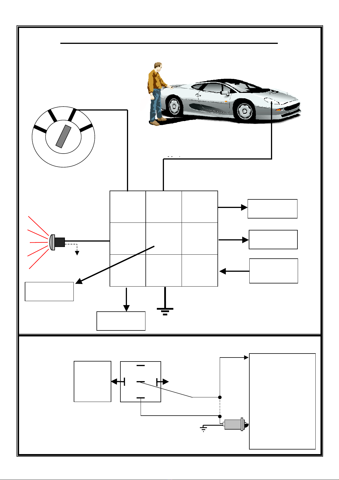
LOCATION GUIDE FOR MAIN UNIT
RECOMMENDED MOUNTING INSTRUCTIONS: The recommended position to mount the unit is vertically
as illustrated below. Where possible, mount the unit as close as possible to the centre of the firewall. Unit
should be at least 25cm away from high tension leads, distributor, or ignition coil. Horizontal mountin
g
increases the sensitivity of the shock sensor. IMPORTANT: Do not allow an
y
part of the vehicle to touch the
unit - no hosin
g
, wirin
g
, or other car components should be able to touch or rub on the unit, as this will affect
t
he sensitivit
y
of the shock sensor. The unit must onl
y
be connected to the vehicle b
y
the mountin
g
bracket. To
adjust the sensitivit
y
level of the alarm shock sensor via the remote controls, please refer to “Pro
g
rammable
Features” located on page 3..
Wiring loom must be furthest away from
firewall.
Mount the unit in a
vertical position.
Horizontal mounting causes Do not run the loom
increased sensitivity. inside the bracket.
Warning sticker is fixed Screw bracket securely
this side. to the firewall.
DO NOT ALLOW THE
UNIT TO TOUCH ANY
PART OF THE VEHICLE:
DOING SO WILL EFFECT
SENSITIVITY.
RECOMMENDED INSTALLATION POSITION OF UNIT
INSTALLERS PLEASE NOTE: If power is removed from the alarm system, it will
automatically return to the mode it was in (armed or disarmed) before power was
disconnected.

8
All relays depicted are changeover type.
CONNECTING TO RHINO CENTRAL LOCKING KIT (CLK)
INSTALLING A NEW MOTOR – often required in vehicles that have factory locking but
have no motor in the driver’s door, or you would like “keyless entry” on driver’s door.
LOCK PULSE
15A FUSE +12V
87 87
UNLOCK 87a 87a
PULSE 86 85 86 85
30 30
LOCK OUTPUT
UNLOCK OUTPUT
NEGATIVE TRIGGER” ORIGINAL CENTRAL LOCKING SYSTEM (LOW CURRENT)
LOCK PULSE WIRE
TO EXISTING
ELECTRONIC INTERFACE
UNLOCK PULSE WIRE
FOR INTEFACING TO “POSITIVE PULSE” CENTRAL LOCKING SYSTEMS
Connect Lock Wire
to Pin 8 on CLK
Control Module
Connect Unlock Wire
to Pin 10 on CLK
Control Module
LOCK PULSE WIRE
15A FUSE +12V
87 87
UNLOCK 87a 87a
86 85 86 85
30 30
LOCK OUTPUT TO VEHICLE
UNLOCK OUTPUT TO VEHICLE

9
FOR POSITIVE AT REST THEN GOING NEGATIVE “OR” NEGATIVE AT REST THEN GOING
POSITIVE PUT 87’S TO 12V & CONNECT RELAYS AS SHOWN
LOCK
+12V +12V OR GROUND (SUPPLY “A”)
15A Fuse
87 87
UNLOCK 87a 87a
86 85 86 85
30 30
+12V
CAR’S CAR
EXISTING CUT CENTRAL
CENTRAL LOCKING
LOCKING INTERFACE
SWITCH
FOR FLOATING SWITCHES - NEITHER +12V OR GROUND AT REST
Hook up the following extra relays & connect Supply “A” to +12V. Both pairs of lock / unlock wires
must be connected.
+12V
87 87
86 85 86 85
UNLOCK LOCK
30 30
15A Fuse
IMPORTANT NOTE FOR INSTALLERS: Vehicles fitted with negative
or positive switching doors.
In order for the alarm system to function correctly, it is necessary for the doors to be
hard wired to the system. Please follow the wiring diagrams below:
NEGATIVE SWITCHING DOORS: POSITIVE SWITCHING DOORS: Use relay.
+12V Interior light
Orange wire ALARM 86
30 87a 87 Orange wire ALARM
Door Switch 85
Door Switch
+12V
Other manuals for GXa
1
Table of contents
Other RHINO Car Alarm manuals
Popular Car Alarm manuals by other brands

Authorized Alarms
Authorized Alarms Controur operating manual

Pandora
Pandora DXL 1840L user manual

Directed Electronics
Directed Electronics Clifford 120XV user guide

Audiovox
Audiovox Pursuit PRO 9544FT installation manual

iDataLink
iDataLink ADS-AL(DL)-SUB2-EN install guide

Clifford
Clifford 520.4X owner's manual

JENN HUEY
JENN HUEY JH-C1R user manual

Xpresskit
Xpresskit OptimaX series installation guide

Directed Electronics
Directed Electronics 560XV installation guide

Directed Electronics
Directed Electronics Hurricane 3 owner's guide

Directed Electronics
Directed Electronics Python 323 owner's guide

Python
Python 44606P owner's guide