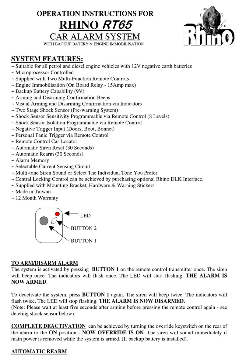
RHINO ACCEL PLUS User manual

OPERATION INSTRUCTIONS FOR
RHINO ACCEL PLUSACCEL PLUS
CAR ALARM SYSTEM
WITH BACKUP BATERY & ENGINE IMMOBILISATION
SYSTEM FEATURES:
~ Suitable for all petrol and diesel engine vehicles with 12V negative earth batteries
~ Microprocessor Controlled
~ Supplied with Two Multi-Function Remote Controls
~ Engine Immobilisation(On Board Relay -15Amp max)
~ Backup Battery Capability (9V)
~ Arming and Disarming Confirmation Beeps
~ Visual Arming and Disarming Confirmation via Indicators
~ Two Stage Shock Sensor (Pre-warning System)
~ Shock Sensor Sensitivity Programmable via Remote Control (8 Levels)
~ Shock Sensor Isolation Programmable via Remote Control
~ Negative Trigger Input (Doors, Boot, Bonnet)
~ Personal Panic Trigger via Remote Control
~ Remote Control Car Locator
~ Automatic Siren Reset (30 Seconds)
~ Automatic Rearm (30 Seconds)
~ Alarm Memory
~ Selectable Current Sensing Circuit
~ Multi-tone Siren Sound or Select The Individual Tone You Prefer
~ Central Locking Control can be achieved by purchasing optional Rhino DLK Interface.
~ Supplied with Mounting Bracket, Hardware & Warning Stickers
~ Made in Taiwan
~ 12 Month Warranty
LED
BUTTON 2
BUTTON 1
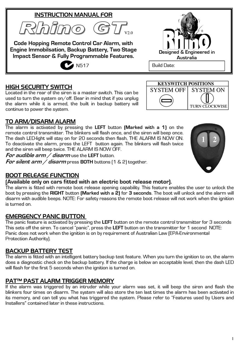
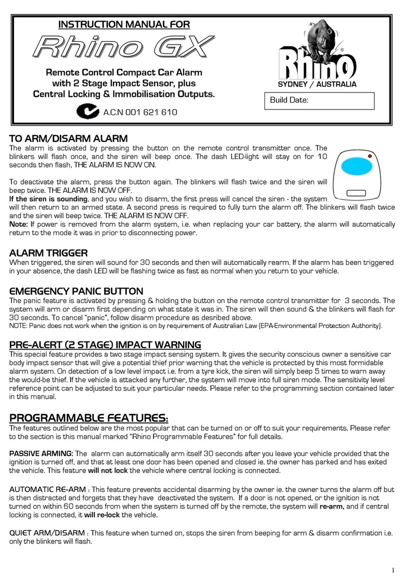
TO ARM/DISARM ALARM
The system is activated by pressing BUTTON 1 on the remote control transmitter once. The siren will beep once. The
indicators will flash once. The LED will start flashing. THE ALARM IS NOW ARMED.
To deactivate the system, press BUTTON 1again. The siren will beep twice. The indicators will flash twice. The LED
will stop flashing. THE ALARM IS NOW DISARMED.
(Note: Please wait at least five seconds after arming before pressing the remote control again -see deleting shock
sensor below).
COMPLETE DEACTIVATION can be achieved by turning the override keyswitch on the rear of the alarm to the
ON position -NOW OVERRIDE IS ON. The siren will sound immediately if main power is removed while the
system is armed. (If backup battery is installed).

AUTOMATIC REARM
This alarm is equipped with automatic rearming. If a door is not opened within 30 seconds of disarming, the system
will automatically re-arm itself. A confirmation beep will be heard to indicate that the system has rearmed itself. If the
alarm is triggered, pressing remote Button 1 once will cancel the siren and rearm the system. The siren will beep
once. Press remote Button 1 again to deactivate the system. The siren will beep four times and the indicators will flash
three times.
ALARM MEMORY
If the alarm has been triggered in your absence, the siren will beep four times on disarm & the indicators will flash three
times . The LED will then indicate what has triggered the system:
1 Flash...pause...1 Flash.... Trigger on current sensing.
2 Flashes...pause...2 Flashes... Trigger from pinswitch or neg. trigger connected to blue wire.
3 Flashes...pause...3 Flashes... Trigger from shock sensor.
The memory readout is given for 30 seconds after disarming, or until the ignition is turned to on.
EMERGENCY PANIC BUTTON OPERATED VIA REMOTE
The panic feature is activated by pressing Button 1 on the remote control transmitter for 3 seconds. This sets off the
siren. To cancel “panic”, press Button 1 on the transmitter for 1 second.
REMOTE CONTROL CAR LOCATOR
This feature is activated by pressing Button 2 on the remote control transmitter for 2 seconds. The siren will beep once
and the indicators will flash 12 times to help you locate your vehicle.
DELETE SHOCK SENSOR
This feature enables the alarm system to be armed without the shock sensor being activated. Simply press Button 1
twice within 3seconds when arming. A confirmation chirp is heard for each press.
TRIGGERING
The siren sounds for 30 seconds then it will reset and rearm itself automatically.
Your Rhino Accel+ Alarm can be triggered by the following three methods:
1. TWO STAGE SHOCK SENSOR (PRE-WARNING SYSTEM)
This special feature provides a two stage impact sensing system. It gives the security conscious owner a sensitive
impact sensor that will give a potential thief prior warning that the vehicle is protected by this alarm system. When the
vehicle is “hit” lightly the siren will simply chirp to warn away the thief. If the vehicle is attacked with a higher level of
impact (i.e. break glass), the system will move into full siren mode.
2. CURRENT SENSING
This feature allows the alarm to be triggered by sensing a drop in voltage through the vehicles electrical system. Where a
door or boot/bonnet switch are wired to the interior light circuit, the alarm will sense the light coming on through the
drop in voltage and trigger the system. The interior light/s must be set to turn on when the doors are opened. The alarm
must be wired to the vehicles interior light circuit exactly as described in the proceeding wiring instructions for this
system to function correctly. If there are accessories in the vehicle that use power after the vehicle is switched off i.e.
car fridges, some mobile phone kits, thermo fans etc. then removal of this feature will be required. See wiring
instructions detailed later.
3. NEGATIVE TRIGGER INPUT (Grounded pin switch)
This feature allows the alarm to be triggered by a negative signal from door/boot/bonnet switches or from optional
sensors such as ultrasonic or microwave detectors.

INSTALLATION INSTRUCTIONS
MOUNTING
1. Mount the alarm in the engine compartment. Be careful not to mount it near hot exhaust
manifolds or areas that are subject to moisture. A position on the firewall is preferable. The siren
should face forwards.
2. Mark & drill two 3/16” holes to fix the mounting bracket. Screw bracket tightly to vehicle.
3. Mount the alarm to the bracket with the nuts, bolts and lock washers supplied. Ensure that the
only thing that will transmit vibrations to the alarm is through the mounting bracket. If hoses etc.
rest on the unit shock sensitivity will be increased.
4. The LED status indicator should be mounted in a highly visible area. Once a suitable location is
chosen, drill a 5/16” hole. Run the LED wires through the hole then press the LED housing into
place. Route the LED wires to the control module.
5. After finishing the installation ,wiring and programming,remove the two screws that hold the
upper case on top of the siren. Insert a 9V Alkaline battery into the compartment and attach the
battery clip. Connect the other end to the adjacent 2 pin connector. Replace the cover.
IMPORTANT NOTE FOR INSTALLERS: Vehicles fitted with negative
or positive switching doors.
In order for the alarm system to function correctly, it is necessary for the doors to be
hard wired to the system. Please follow the wiring diagrams below:
NEGATIVE SWITCHING DOORS: POSITIVE SWITCHING DOORS: Use relay.
+12V Interior light
BLUE wire ALARM 86
30 87a 87 BLUE wire ALARM
Door Switch 85
Door Switch
+12V
IMPORTANT NOTE:Vehicles fitted with an interior light delay.
Some vehicles fitted with an interior light delay require a diode to be added
to prevent the system triggering due to voltage drop (current sensing).
Please follow the wiring diagram below:
Interior light
DOOR DELAY
CIRCUIT
llll
llll
+12V
Blue wire Place a diode here
RHINO
Door Switches
OPTIONAL 30/40AMP IMMOBILISATION CIRCUIT
Install 30/40amp changeover relay as shown below:
To orange wire from alarm (negative on arm -500mA)
87
IGN 86 87a 85
30
"CUT
Original wire to fuel pump/starter motor/ ign. coil

PROGRAMMING AND ADJUSTMENT
The Rhino Accel+ Alarm System allows for customisation of both siren sound type and
shock sensor sensitivity.
Programming Remote Controls: To program, disconnect all power to alarm (i.e. remove fuse &backup
battery). After 10 seconds replace the fuse. Press Button 1 on the first remote control. A single confirmation chirp
should be heard. If you intend to use the second remote control, press Button 1 on this remote within 5 seconds of the
first remotes confirmation chirp. A single chirp will be given to confirm that this remote is also learnt into the alarm. Now
install the backup battery.
Note: Whenever power is lost to the alarm, i.e. both the backup battery & the car battery are disconnected,
this procedure must be repeated, as remote codes are not retained in memory. This will enable you to delete
a remote in case it is lost or stolen.
Adjusting Shock Sensor Sensitivity: Your Rhino Accel+ Alarm has an 8 Level adjustable, two stage shock
sensing system. Test the sensitivity of this system by arming the alarm and waiting three seconds. Strike the front
windows, or hood with your palm. At this low level of impact you should hear the pre-warning chirp. If you wish to
increase or decrease sensitivity follow this procedure:
1. Within 10 seconds of disarming the alarm, press down both Buttons 1 & 2 on the remote control for two seconds. A
single chirp will be given to confirm that you have entered the programming mode.
2. Press Button 2 to enter choosing shock sensitivity. By pressing Button 2 again you are able to scroll through the 8
levels and corresponding tones. The higher the pitch of the tone, the more sensitive the alarm is to shock vibrations. At
any time you can stop to test the setting. ( A chirp sound given indicates pre-warning level of impact detected, designed
to warn away the would be thief, the ding-dong sound indicates that the alarm would have triggered to full siren sound if
the vehicle had been hit at this higher level). Note: the last level is to turn off the shock sensor, corresponding with a
chirp sound.
3. Once you are happy with the level of sensitivity, press Button 1 to exit the programming mode and to save the
chosen sensitivity level. Two confirmation chirps will be given. If you don’t press any buttons within 10 seconds, the
system will automatically exit the programming mode.
4. To avoid the possibility of false alarms, please take care to adjust the sensor so that it is not
over sensitive.
Choosing Siren Tone: Your Rhino Accel+ Alarm has the ability to sound in either 5 Tone or Single Tone
operation. If you prefer to choose a single tone siren sound follow this procedure:
1. Within 10 seconds of disarming the alarm, press down both Buttons 1 & 2 on the remote control for two seconds. A
single chirp will be given to confirm that you have entered the programming mode.
2. Press Button 1 to enter choosing siren sound. By pressing Button 1 again you are able to scroll through the 5
different tones and multi-siren sound.
3. Once you are happy with the siren sound, press Button 2 to exit the programming mode and to save the last sound
played. Two confirmation chirps will be given. If you don’t press any buttons within 10 seconds, the system will
automatically exit the programming mode.

WIRING INSTRUCTIONS
RED & RED/WHITE +12 VOLTS DC
OVERRIDE KEYSWITCH:
WHEN KEY IS AT ON POSITION, BLACK Earth
OVERRIDE IS ON (ALARM IS TURNED OFF) ORANGE Neg. Out on Arm (500mA)
ANTENNA WHITE X 2 Left and Right Indicators
YELLOW CUT HERE FUEL PUMP
YELLOW
BLACK/WHITE NEGATIVE LED
+12VDC
VIOLET CURRENT SENSE OVERRIDE
BLUE NEGATIVE TRIGGER INPUT
RED & RED/WHITE -
Connect to constant +12 volts via the fuse box at the point where the interior light circuit is
powered. Current (voltage) sensing will not work correctly if this procedure is not followed.
The red/white wire is the common power source for the indicator flash circuit.
BLACK -
Connect to a suitable earth point on the car body.
(e.g. mounting bolt to vehicle chassis)
BLUE -
-
-
Connect to pin switch for bonnet
Connect to pin switch for boot
Connect to Neg. Trigger from optional sensors i.e. ultrasonics.
YELLOW (X2) -
Connect to an ignition switched 12VDC isolation circuit: locate the positive feed wire to the
fuel pump. Cut that wire and join the two yellow wires to either end of the wire which you
have just cut. Warning: Internal cut out relay has 15amp max rating. Disable only fuel pump
or ignition coil if vehicle is not EFI. If more than 15amp cutout rating is required, you must
install a 30/40amp changeover relay as shown in earlier diagram. Under no circumstances
should you cut the vehicle’s main ignition system.
WHITE (X2) -Connect to left & right indicator circuits. When the alarm is triggered these two wires provide
+12VDC output (5amps).
ORANGE -
This is a switched negative output (-
ve 500mA). Use this wire to drive a 30/40amp
changeover relay as shown in earlier diagram, if greater than 15amp circuit is to be
immobilised or this wire can be used to connect alarm to central locking -an optional RHINO
DLKACCEL MODULE is required when connecting to vehicles that have existing central
locking, or connect this wire to PIN 8 on RHINO’s CLKACCEL Central Locking Kit
Control Module.
BLUE -
This is a negative trigger input and should be connected to the output circuit wire on any
accessory to be used. (i.e. ultrasonic, microwave, or glass breaks, etc.)
VIOLET -The alarm is fitted standard with current sensing. This feature has been proven to be very
reliable. The alarm will detect any sudden drop in voltage in the vehicle’s electrical system,
for example if the interior light comes on, or if the electrical system shows a voltage drop
through tampering. If removal of this feature is necessary connect the violet wire to the
red power wire (+12VDC).
THIN BLACK WIRE -This is the antenna for the alarm. Do not cut. Optimum performance is achieved where the
antenna is simply hanging in as much free space as possible and away from metal objects.
RED FROM LED -Connect to constant +12VDC.
BLACK/RED FROM
LED -Connect to black/white wire from alarm.

Important Notes for Installers:
PROGRAMMING REMOTE CONTROLS:PROGRAMMING REMOTE CONTROLS:
If you find that only one remote control is working, check that you have followed this procedure:
To program, disconnect all power to alarm (i.e. remove fuse &backup battery). After 10 seconds replace the fuse.
Press Button 1 on the first remote control. A single confirmation chirp should be heard. If you intend to use the second
remote control, press Button 1 on this remote within 5 seconds of the first remotes confirmation chirp. Another single
chirp will be given to confirm that this remote is also learnt into the alarm. Now install the backup battery.
Note: Whenever power is lost to the alarm, i.e. both the backup battery & the car battery are disconnected,
this procedure must be repeated, as remote codes are not retained in memory. This will enable you to delete
a remote in case it is lost or stolen.
CENTRAL LOCKING CONNECTION:CENTRAL LOCKING CONNECTION:
The Rhino Accel Plus does not provide dedicated central locking output wires i.e. separate lock & unlock pulses.
Instead, the negative on arm wire from the Accel Plus can be utilised to activate our after-market central locking kit,
provided the following simple modification is made to the central locking control module.
If you already have existing factory fitted central locking in your vehicle, you will require an additional part –
DLKACCEL. Contact your dealer for further information.
Parts required:
1 x 2k2ΩResistor (Red,Red,Red,Gold)
Procedure:
Remove the printed circuit board from the control module. This is achieved by gently prising out the surround around
the connector block & sliding out the PCB. The modification is carried out on the back of the board.
Solder a wire link
between these two
square pads
Solder the resistor
between these two
round pads.
Connect ORANGE wire
from Accel Plus to PIN 8
on control module.
Table of contents
Other RHINO Car Alarm manuals
Popular Car Alarm manuals by other brands

Directed Electronics
Directed Electronics Python 990 owner's guide

Mobile Devices
Mobile Devices C4evo installation guide

DesignTech
DesignTech Smart Alarm 20620 installation manual

Black Widow
Black Widow BW1700 installation manual

CrimeStopper
CrimeStopper CS-882 OEM Installation and operating instructions

Prestige
Prestige APS-510E owner's guide