RHINO BLX 65 BMR User manual

ELEKTROBOOTSMOTOREN
MOTEURS ELECTRIQUES
SILNIKI ELEKTRYCZNE
MOTORE ELETTRICO
ELEKTROMOS CSÓNAKMOTOROK
ELEKTRISCHE BUITENBOORDMOTOREN
ZÁVĚSNÉ ELEKTROMOTORY
ELEKTRICKÉ MOTORY
ELECTRIC OUTBOARD MOTOR
Owners Manual
Bedienungsanleitung
Manuel d'utilisation
Manuale d’istruzioni
Instrukcja Obsługi
Handboek
Instrukcja obsługi
manuál
Návod na používanie
Manuel d'utilisation
Manuale d’istruzioni

2
Rhino propeller
Multi adjustable depth feature
Motor unit
Electrically pivoting steering head
Battery cable
Bow assembly unit with folding
device and Display
Aluminium composite shaft
Remote control

3
2. SYSTEM OVERVIEW AND SETUP
2.1 Charge indicator display
The display continuously shows the
battery charge status once the motor
has been connected to the battery.There is a display on the
mounting unit.
2.3 Assembly
Attach the engine in the bow area.The scope of delivery includes
the holder made of nylon material (Fig. 1), which is xed to the
motor with a bracket (Fig. 2). Position the motor so that the shaft
is far enough from the hull when folded out. Connect the motor
holder to the deck using the holes provided (Fig. 1).
Optionally available: Quick release motor holder set, Art. no.
9940 101 (Fig. 3).
RHINO BLX GPS MOTOR USER GUIDE
1. GENERAL
Introduction ......................................................................... 1.1
Warranty terms .................................................................... 1.2
2.SYSTEM OVERVIEW AND SETUP
Charge indicator display........................................................ 2.1
Assembly .............................................................................. 2.2
Starting the motor ............................................................... 2.3
Move the motor to the resting position................................. 2.4
Adjusting the depth.............................................................. 2.5
Changing propellers – Detaching the propeller.................... 2.6
Electrical connections (for 12V batteries only!)..................... 2.7
Remote control ..................................................................... 2.8
3. MAINTAINANCE
Troubleshooting.................................................................... 3.1
4. DECLARATION OF CONFORMITY
1. GENERAL
1.1 Introduction
Congratulations on your purchase of a Rhino electric
boat motor.
This motor was developed by ZEBCO and specially designed
to meet the needs of anglers. High quality materials, superior
design and state-of-the-art engineering make this motor a
long-lived and reliable companion in all situations.
As a means of constant product improvement, we reserve the
right to change parts and components without notice. Please
read this manual carefully to avoid potential operating errors.
1.2Warranty terms
Zebco oers a two (2) year warranty on the Rhino electric
boat motor, beginning on the date of purchase (valid only in
connection with your purchase receipt).
The warranty does not extend to wearing parts.The warranty
is limited to non-commercial use of the motor and does not
apply in case of operating errors, accidents, improper repair or
modication.
Any servicing or repair work must be carried out by Zebco
Europe.
2
3
1
PAUR ON/OFF
BATTERY LEVEL

4
CAUTION: Make sure you detach the motor before
taking the boat out of the water.When mounting
or detaching the motor, make sure, that the
battery is disconnected.
CAUTION!When adjusting the tilt angle, avoid placing your
hands between the shaft and the hull of the boat – risk of
injury! If the motor is to remain attached to the boat after
use, it must always be lifted out of the water via the
pivoting mechanism.
2.4 Starting the motor (Fig. 4 & 5)
Press the release lever (A). Carefully push the motor into
direction (B) by the shaft let the height adjustment snap into
the steering unit (C).
2.5 Move the motor to the resting position (Fig. 4)
Press the release lever (A). Carefully pull the motor into
direction (B) by the shaft until it locks into place. Slide the
height adjustment into direction (B) and tighten.
2.5 Adjusting the depth
Hold the motor shaft
with one hand, then
loosen the depth
adjustment screw and set
the motor to the desired
depth.
Engage the depth
adjustment in the
steering unit (Fig. 6)
and then tighten.Then
align the motor head if
necessary.
2.6 Changing propellers
Detaching the propeller
Unscrew and remove the locknut using the propeller wrench
supplied, taking care to hold the propeller with one hand
to prevent it from revolving. Do not loosen the locknut with
a hammer or similar tool, as this may cause damage to the
locknut or shaft.
Once the locknut has been removed, the propeller can be taken
o easily.Verify proper t of the groove and shearing pin when
mounting the new propeller, otherwise the propeller will not
attach properly.
After using the motor, always check for shing line or weeds
that may have got caught in the propeller and remove, if
necessary.
CAUTION: ALWAYS disconnect the battery
prior to changing the propeller.
2.7 Electrical connections
(For 12V batteries only!)
Connect the red battery cable (A) to the positive battery
terminal (labeled (+) on the battery). Connect the black battery
cable (B) to the negative battery terminal (-).
5
C
4
B
D
A
6

5
Connect the terminal clamps securely. Otherwise you may have
trouble using the motor.
The battery should always be kept in a well-ventilated location.
The motor runs with all standard 12V batteries.We recommend
using a special low charge marine battery or a LiFeP04 battery
for optimum performance.
CAUTION: Any changes to the factory
installed battery connections will void the
warranty. The electric pole clips must be
connected securely, otherwise there may
be disruption in the electric current.
2.8 Remote control
Please see the GPS Owner's Manual for information on the
functions of the remote control.
3. MAINTAINANCE
After use, carefully rinse the motor unit with running water and
wipe the control unit with a damp cloth.
On a monthly basis, inspect the electrical connections for signs
of corrosion. Replace defective terminals or cables immediately
to prevent possible overheating.
After approx. 100 hours of service, the graphite brushes of the
driving unit should be replaced by Zebco Customer Service.
Be sure to choose a well-ventilated and dry location when
storing the motor for longer periods.
Do not leave the motor outdoors during the winter, as this could
cause damage to the drive unit and the control unit.
3.1Troubleshooting
Loss of performance
• Propeller action might be„sti“. Check to see if line or weeds
have got caught in the propeller.
• Check the battery charge status. Check the battery cells.
• Check the terminals on the battery cable.
Power consumption is too high
• Check for„sti“ propeller action
• Corrosion or short circuit in top motor housing
• Check the battery cells
Motor sounds too loud and/or shakes
• Check t and condition of the propeller; you may have to ret
the propeller, turning it by 180°.
• Bent shaft. Detach propeller and run motor at low speed,
listening for abnormal sounds from shaft.
• If shaft is bent, return motor to Zebco for repair.
•Turn propeller by hand; return motor to Zebco if action is sti.
Remote control non functional
• change battery
• synchronize with motor again
For all other problems not listed above, please contact
your dealer or Zebco Customer Service.
Red (+)
Black (–)
A
B
BLX 65 BMR GPS 12 V

6
Rhino Propeller
stufenlos verstellbareTiefeneinstellung
Antriebseinheit
Elektrisch schwenkbarer Steuerkopf
Batteriekabel
Bug-Montageeinheit mit
Klappvorrichtung und Display
Alu-Composite Schaft
Fernbedienung

7
2. AUFBAU UND INBETRIEBNAHME
2.1 Ladekontroll-Display
Das Display zeigt den aktuellen
Batterie-Ladezustand durchgehend
an, sobald der Motor an die Batterie angeschlossen wird. Eine
Anzeige bendet sich auf der Montageeinheit.
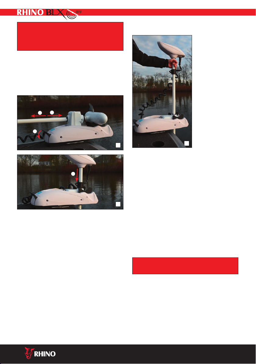
2.3 Montage
Befestigen Sie den Motor im Bugbereich. Im Lieferumfang
bendet sich die Standard Motor Halterung aus Nylonmaterial
(Abb. 1), welche mit einem Bügel am Motor xiert wird (Abb. 2).
Motor so positionieren, dass sich der Schaft im ausgeklapptem
Zustand ausreichend weit vom Bootsrumpf entfernt bendet
(min 2cm). Motorhalter über die vorgesehenen Bohrungen der
Halteplatte mit dem Deck verbinden (Abb. 1).
Optional erhältlich: Motorhalter-Set Quick Release Art. No. 9940
101 (Abb. 3)
RHINO BLX GPSMOTOR BENUTZERHANDBUCH
1.ALLGEMEINES
Einleitung ............................................................................. 1.1
Garantiebedingungen .......................................................... 1.2
2.AUFBAU UND INBETRIEBNAHME
Ladekontroll-Display............................................................. 2.1
Montage ............................................................................... 2.2
Motor ablassen ..................................................................... 2.3
Motor in Ruheposition bringen............................................. 2.4
Tiefeneinstellung.................................................................. 2.5
Austausch des Propellers – Lösen des Propellers .................. 2.6
Elektro-Anschluss (Nur für 12V-Batterien!)........................... 2.7
Fernbedienung ..................................................................... 2.8
3.WARTUNG
Fehlersuche........................................................................... 3.1
4. DECLARATION OF CONFORMITY
1. ALLGEMEINES
1.1 Einleitung
Herzlichen Glückwunsch zum Kauf eines Rhino-Elektro-
Bootsmotors.
Dieser Motor ist eine Entwicklung aus dem Hause ZEBCO,
speziell abgestimmt auf die Anforderungen des Angelsports.
Hochwertiges Material und Design im Zusammenspiel mit aus-
gereifterTechnik machen diesen Motor zu einem langlebigen,
verlässlichen Partner in allen Situationen.
Zur ständigenVerbesserung unserer Produkte behalten
wir es uns vor, Bauteile und Komponenten ohne vorherige
Ankündigung oder Mitteilung zu verändern. Um unnötige
Bedienungsfehler zu vermeiden, lesen Sie die nachfolgende
Betriebsanleitung bitte sorgfältig durch.
1.2 Garantiebedingungen
Für den Rhino-Elektro-Bootsmotor gilt eine Garantiefrist von
2 Jahren (nur gültig in Verbindung mit dem Kaufbeleg),
beginnend mit dem Erwerb.
Die Garantie beinhaltet keineVerschleißteile. Sie erstreckt
sich ausschließlich auf die nicht-kommerzielle Nutzung des
Motors und gilt nicht im Falle von Bedienungsfehlern, Unfällen,
unsachgemäßer Reparatur oder vorgenommenen Änderungen.
Service Leistungen und Reparaturen dürfen ausschließlich von
Zebco Europe GmbH vorgenommen werden.
2
3
1
PAUR ON/OFF
BATTERY LEVEL

8
ACHTUNG: Soll das Boot aus demWasser
genommen werden, ist der Motor unbedingt
vorher zu demontieren.Vor der Montage bzw. der
Demontage unbedingt die Batterie abklemmen.
ACHTUNG!Während des Einstellens des Kippwinkels die
Hände nicht zwischen Schaft und Bootskörper bringen
–Verletzungsgefahr! Wenn der Motor nach dem
Einsatz am Boot verbleibt, muss er immer mittels
Schwenkvorrichtung aus dem Wasser gehoben und
abgedeckt werden.
2.4 Motor ablassen (Abb. 4 & 5)
Auslösehebel (A) drücken und Motor am Schaft vorsichtig Rich-
tung (B) schieben und die Höhenverstellung in der Lenkeinheit
einrasten lassen (C).
2.5 Motor in Ruheposition bringen (Abb. 4)
Auslösehebel (A) drücken und Motor am Schaft vorsichtig
Richtung (D) bis zum Einrasten ziehen. Höhenverstellung in
Richtung (B) schieben und festziehen.
2.5Tiefeneinstellung
Den Motorschaft mit
einer Hand festhalten,
dann die Schraube an
derTiefeneinstellung
lösen und den Motor auf
die gewünschteTiefe
justieren.
Tiefeneinstellung in die
Lenkeinheit einrasten
(Abb. 6) und dann
festziehen. Anschließend
gegebenfalls den
Motorkopf ausrichten.
2.6 Austausch des Propellers
Lösen des Propellers
Mit dem mitgelieferten Propellerschlüssel die Sicherungsmut-
ter lösen und entfernen, dabei muss der Propeller mit einer
Hand festgehalten werden, um ein Mitdrehen zu verhindern.
Die Sicherungsmutter darf nicht mit Hammerschlägen oder
ähnlichem gelöst werden, da dies eine Beschädigung der
Mutter oder derWelle zur Folgen haben könnte.
Der Propeller kann nach dem Entfernen der Sicherungsschraube
leicht abgenommen werden. Bei dem Aufsetzen des neuen
Propellers auf die Passung von Nut und Scherstift achten, sonst
lässt sich der Propeller nicht richtig befestigen.
Nach jedem Gebrauch den Propeller auf eventuell verfangene
Schnüre oderWasserpanzen überprüfen und diese
gegebenenfalls entfernen.
ACHTUNG: Unbedingt die Batterie vor dem
Wechsel des Propellers abklemmen.
2.7 Elektro-Anschluss
(Nur für 12V-Batterien!)
Das rote Batteriekabel (A) mit dem Pluspol verbinden
(gekennzeichnet durch (+) auf der Batterie). Das schwarze
Batteriekabel (B) mit dem Minuspol verbinden (-).
5
C
4
B
D
A
6

9
Die Polklemmen müssen fest angeschlossen werden. Ansonsten
kann es zu Störungen kommen.
Die Batterie sollte immer an einem gut belüfteten Ort aufge-
stellt werden. Der Motor arbeitet mit allen herkömmlichen
12V-Batterien, Zebco empehlt dieVerwendung von speziellen
Marine-Tieadungsbatterien oder LiFeP04-Batterien, um den
bestmöglichen Betrieb zu gewährleisten.
ACHTUNG: BeiVeränderung der werkseitig
montierten Batterieanschlüsse erlischt
die Garantie. Die Polklemmen müssen fest
angeschlossen werden. Ansonsten kann es
zu Störungen kommen.
2.8 Fernbedienung
Siehe GPS-Bedienungsanleitung für detaillierte Informationen
über die Funktionen der Fernbedienung.
3.WARTUNG
Das Motorteil nach Gebrauch sorgfältig mit ießendemWasser
abspülen und das Steuerteil mit einem feuchten Lappen
abwischen.
Monatlich sollten die Elektro-Anschlüsse auf Korrosion
überprüft werden. Defekte Anschlüsse oder Kabel sofort
auswechseln, um etwaige Überhitzung zu vermeiden.
Zur längerfristigen Lagerung muss der Motor an einem gut
belüfteten, trockenem Ort aufbewahrt werden.
Lassen Sie den Motor über denWinter nicht im Freien, das
könnte zur Beschädigung der Antriebseinheit und der Steuer-
einheit führen.
3.1 Fehlersuche
Leistungsverlust
• Propeller eventuell schwergängig. Überprüfen, ob sich Schnur
oder Algen in der Schraube verfangen haben.
• Ladezustand der Batterie prüfen. Batteriezellen überprüfen.
• Anschlüsse des Batteriekabels prüfen.
Zu hoher Stromverbrauch
• Propeller auf Schwergängigkeit überprüfen
• Korrosion oder Kurzschluss an Kabelsteckern im oberen
Motorgehäuse
• Batteriezellen überprüfen
Zu lautes Motorgeräusch/Vibrationen
• Sitz und Zustand des Propellers überprüfen, eventuell Propel-
ler um 180° versetzt neu montieren.
•VerbogeneWelle. Propeller abnehmen und Motor mit
mittlerer Geschwindigkeit laufen lassen, aufWellengeräusche
achten.
• Bei verbogenerWelle den Motor zur Reparatur einsenden.
• Den Propeller mit der Hand drehen, bei Schwergängigkeit
Motor einsenden.
Fernbedienung ohne Funktion
• Batterie wechseln
• erneut mit Motor synchronisieren
Bei allen anderen Problemen wenden Sie sich bitte an
Ihren Fachhändler oder an den Zebco-Service-Dienst.
Rot (+)
Schwarz (–)
A
B
BLX 65 BMR GPS 12 V

10
Hélice Rhino
Commande d'ajustement de
la profondeur du moteur
Unité basse du moteur
Tête de moteur à rotation électrique
Câble de la batterie
Socle de xation avant avec dispositif de
verrouillage horizontal et achage
Mât alu-composite
Télécommande

11
2. DESCRIPTION ET MISE EN SERVICE
2.1 Écran indicateur de charge
L’écran indique continuellement le
niveau de charge de la batterie, une
fois que le moteur y est connecté. Un achage se situe sur
l’unité de montage.
2.3 Montage
Fixez le moteur sur l’avant du bateau. La xation moteur standard
en matériau nylon est fourni (Fig.1), elle est xée au moteur à
l’aide d’un arceau (Fig.2) Positionner le moteur pour qu’il soit
susamment éloigné de la coque avec l’arbre immergé (min
2cm). Fixer le socle du moteur au bateau à travers les trous prévus
à cet eet (Fig 1).
Option disponible : kit de xation moteur à démontage rapide
Art. No. 9940 101 (Fig. 3).
MOTEUR RHINO BLX GPS GUIDE D‘UTILISATION
1. GÉNÉRALITÉS
Introduction ......................................................................... 1.1
Conditions de garantie ......................................................... 1.2
2.DESCRIPTION ET MISE EN SERVICE
Écran indicateur de charge.................................................... 2.1
Montage ............................................................................... 2.2
Descendre le moteur ............................................................ 2.3
Mettre le moteur en position de repos ................................. 2.4
Réglage de profondeur ......................................................... 2.5
Remplacement de l’hélice – Démontage de l’hélice............. 2.6
Electrical connections (for 12V batteries only!)..................... 2.7
Télécommande ..................................................................... 2.8
3. ENTRETIEN
En cas de problème............................................................... 3.1
4. DECLARATION OF CONFORMITY
1. GENERAL
1.1 Introduction
Nous vous remercions d’avoir choisi un moteur hors-bord
électrique Rhino.
Spécialement conçu par les équipes de ZEBCO, ce moteur est
parfaitement adapté aux exigences de la pêche sportive. Des
matériaux de haute qualité et un design étudié alliés à une tech-
nologie sophistiquée font de ce moteur un partenaire sur lequel
vous pourrez compter longtemps et dans toutes les situations.
Nous sommes attachés à l’amélioration constante de nos
produits et nous réservons le droit de modier des pièces et
composants sans préavis ni notication. Pour éviter toute
mauvaise manipulation, veuillez lire attentivement la notice
d’utilisation et les instructions associées.
1.2 Conditions de garantie
Le moteur électrique Rhino est couvert par une garantie de 2
ans (sur présentation obligatoire du justicatif d’achat)
à compter de la date de l’achat.
La garantie ne comprend pas les pièces d'usure. La garantie
s’applique exclusivement à une utilisation non commerciale du
moteur et ne couvre pas les erreurs de manipulation, accidents,
réparations non conformes ou modications non autorisées.
Toute intervention ou réparation devra être réalisée exclusive-
ment par Zebco Europe GmbH.
2
3
1
PAUR ON/OFF
BATTERY LEVEL

12
ATTENTION: Démontez toujours le moteur avant
de sortir le bateau de l’eau. Lors du montage et du
démontage du moteur assurez-vous toujours qu'il
ne soit pas branché à la batterie.
ATTENTION ! Pendant le réglage de l’angle d’inclinaison,
ne pas introduire les mains entre l’arbre et la coque - Risque
de blessures ! Lorsque le moteur reste à demeure sur le
bateau et qu’il n’est pas en fonctionnement, nous vous
conseillons de toujours le rabattre hors de l’eau et de le
couvrir.
2.4 Descendre le moteur (image 4 & 5)
Déverrouiller le moteur en poussant la manette vers (A) puis
pousser doucement le moteur en direction de B en le tenant
par l’arbre. Laissez ensuite le verrouillage de profondeur C
s’enclencher.
2.5 Mettre le moteur en position de repos (image 4)
Pousser le verrou (A) et tirer doucement le moteur en direction
(D) en le tenant par l’arbre, jusqu’à l’enclenchement sur la
fourchette. Pousser le réglage de hauteur de mât vers (B) puis
verrouiller.hauteur de mât vers (B) puis verrouiller.
2.5 Réglage de profondeur
Tenir le mât avec une
main et dévisser la vis de
réglage de profondeur
puis régler à la profon-
deur voulue.
Enclencher le réglage
de profondeur dans le
module de direction
(image 6) puis verrouiller
Puis éventuellement
régler direction de la tête
de moteur.
2.6 Remplacement de l’hélice
Démontage de l’hélice
Desserrer l’écrou de xation au moyen de la clé spéciale fournie
et le retirer. Pendant cette opération, maintenir l’hélice d’une
main an d’éviter qu’elle ne tourne. Ne jamais tenter de
débloquer l’écrou avec un marteau ou outil similaire sous peine
de risquer d’endommager l’écrou ou l’arbre.
Une fois la vis de xation retirée, l’hélice peut être ôtée
facilement. Lors de la mise en place de la nouvelle hélice, veiller
à bien aligner l'ergot de cisaillement sur la rainure. Dans le cas
contraire, il ne sera pas possible de xer correctement l’hélice.
Après chaque utilisation, vérier que des plantes aquatiques ou
du l de pêche ne soient pas enroulés sur l’hélice. Les retirer le
cas échéant. Rincer soigneusement le moteur à l’eau courante.
ATTENTION : Déconnecter obligatoirement la
batterie avant le remplacement de l’hélice.
2.7 Branchement électrique
(Uniquement pour batteries 12V !)
Raccorder le câble rouge de la batterie (A) au pole plus (indiqué
par le signe (+) sur la batterie). Relier le câble noir de la
batterie (B) au pole moins (-).
5
C
4
B
D
A
6

13
Il est impératif de bien serrer les bornes polaires pour éviter
tout risque de dysfonctionnement.
Toujours installer la batterie à un endroit bien aéré. Le moteur
fonctionne avec toutes les batteries 12V classiques. Pour des
résultats optimaux, Zebco préconise l’emploi de batteries de
basse charge spéciales marine ou batteries LiFeP04.
ATTENTION : La garantie sur la réparation
du moteur est caduque dès lors qu’il y a eu
changement des pôles de jonction à la batterie
installés à l’origine par le fabriquant.
Les pinces doivent être attachées très solidement
à la batterie pour éviter les défauts de
fonctionnement.
2.8Télécommande
Merci de consulter la notice d’utilisation du module GPS conte-
nant les informations utiles de la télécommande.
3. ENTRETIEN
Après utilisation, rincer correctement la partie moteur à l’eau et
essuyer uniquement au chion humide la partie de commande.
Une fois par mois, vérier l’absence de corrosion sur tous les
branchements électriques.Tout raccord ou câble endommagé
devra être remplacé immédiatement pour éviter les risques de
surchaue.
Au bout d’une centaine d’heures de fonctionnement, faire
remplacer les balais de charbon du propulseur par le service
après-vente Zebco. En cas de remisage prolongé, conserver le
moteur dans un endroit bien aéré et sec.
Durant l’hiver ne laissez pas le moteur à l’air libre, ceci pourrait
l’endommager
3.1 En cas de problème
Baisse de puissance
• L’hélice tourne mal.Vérier qu’aucun l de pêche ni d'algues
ne soient pris dans l'hélice.
•Vérier que la batterie est susamment chargée, contrôler les
éléments de la batterie.
•Vérier les raccords du câble de batterie.
Consommation trop élevée
•Vérier si l’hélice tourne bien.
• Corrosion ou court-circuit au niveau des ches de câble dans le
haut du bâti de moteur.
• Contrôler les éléments de la batterie.
Moteur trop bruyant/Vibrations
•Vérier la bonne xation et l’état de l’hélice, la remonter
éventuellement en la retournant de 180°.
• L’arbre est tordu. Retirer l’hélice et faire tourner le moteur
à vitesse moyenne en tentant de déterminer si les bruits
proviennent de l’arbre.
• Si l’arbre est tordu, renvoyer le moteur au service après-vente.
• Faire tourner l’hélice à la main, en cas de résistance, renvoyer
le moteur au service après-vente.
Télécommande sans fonction
• changer la batterie
• re-synchroniser avec le moteur
Pour tout autre dérangement non mentionné ici,
veuillez vous adresser à votre revendeur spécialisé ou au
service après-vente de Zebco.
Rouge (+)
Noir (–)
A
B
BLX 65 BMR GPS 12 V

14
Elica Rhino
Regolatore di profondità
Corpo motore
Sterzo a rotazione elettrica
Cavo batteria
Unità di supporto con
display e leva di sgancio
Albero in composito di alluminio
Telecomando

15
2. CONFIGURAZIONE DEL SISTEMA E SETUP
2.1 Indicatore carica batteria
Il display indica costantemente il
livello di carica non appena il motore
viene collegato alla batteria. C'è un display situato sull'unità di
supporto del motore.
2.3 Assemblaggio
Installare il motore sulla prua della barca. Rimuovere la cover la-
terale (svitare le due viti, Fig. 1). Posizionare il motore di modo
che l’albero sia sucientemente lontano dalla scafo quando è
in funzione. Collegare il supporto del motore al pianale della
barca utilizzando i fori di ssaggio (Fig. 2).
Optional disponibile: Set rilascio rapido del motore, Art. 9940101
(Fig. 3).
RHINO BLX GPS MOTOR MANUALE D’USO
1. GENERALE
Introduzione ........................................................................ 1.1
Termini di garanzia ............................................................... 1.2
2.CONFIGURAZIONE DEL SISTEMA E SETUP
Indicatore carica batteria ...................................................... 2.1
Assemblaggio....................................................................... 2.2
Posizionamento del motore ................................................. 2.3
Sollevamento del motore nella posizione di riposo .............. 2.4
Regolazione della profondità................................................ 2.5
Sostituzione dell’elica – Distacco dell’elica ........................... 2.6
Connessione elettrica (Per batterie da 12V))......................... 2.7
Telecomando ........................................................................ 2.8
3. MANUTENZIONE
Risoluzione dei problemi ...................................................... 3.1
4. DECLARATION OF CONFORMITY
1. GENERALE
1.1 Introduzione
Congratulazioni per aver acquistato un motore elettrico
Rhino.
Questo motore è stato sviluppato dalla ZEBCO e progettato spe-
cicatamente per incontrare le richieste dei pescatori. Materiali
d’alta qualità, design moderno ed ingegneria all’avanguardia
fanno di questo motore un valido compagno, adabile in ogni
condizione d’impiego.
Allo scopo di apportare continui miglioramenti, ci riserviamo il
diritto di cambiare parti o componenti senza preavviso. Leggere
questo manuale con attenzione per evitare eventuali errori di
utilizzo..
1.2Termini di garanzia
Zebco Europe garantisce i motori elettrici RHINO per due (2)
anni a partire dalla data d’acquisto (valida solo se provata da
relativo scontrino scale).
La garanzia non include particolari soggetti ad usura. La
garanzia è limitata all’uso non professionale del motore e non
è rivendicabile in caso di errore d’utilizzo, incidente, riparazione
impropria o modica.
Ogni intervento di manutenzione o riparazione deve essere
svolto dagli addetti della Zebco Europe.
2
3
1
PAUR ON/OFF
BATTERY LEVEL

16
ATTENZIONE: Assicuratevi di rimuovere il motore
prima di estrarre l’imbarcazione dall’acqua.
Durante le fasi di montaggio o smontaggio del
motore, assicuratevi che la batteria sia scollegata.
ATTENZIONE! Durante le fasi di regolazione dell’inclinazione
NON mettete le mani tra l’albero e lo scafo della barca –
potreste ferirvi! Se lasciate il motore montato sulla barca
dopo l’uso, assicuratevi di sollevarlo oltre il livello
dell’acqua.
2.4 Posizionamento del motore (Fig. 4 & 5)
Premere la leva di sgancio (A). Spingere con cautela il motore
(B) attraverso il gambo e lasciare che il blocco che regola
l'altezza si appoggi sulla base (C).
2.5 Sollevamento del motore nella posizione
di riposo (Fig. 4)
Premere la leva di rilascio (A). Sollevare con cura il motore
lungo l’albero e ssarlo in posizione di riposo. Regolare la
posizione orizzontale di riposo (B) e ssare con cura.
2.5 Regolazione della profondità
Tenere l'albero del
motore con una mano,
quindi allentare la vite
di regolazione della
profondità e impostare
il motore alla profondità
desiderata.
Inserire la regolazione
della profondità nell'uni-
tà di guida (Fig. 6), quindi
serrare. Allineare la testa
del motore se necessario.
2.6 Sostituzione dell’elica
Distacco dell’elica
Svitare e rimuovere la vite di ssaggio utilizzando la chiave for-
nita, assicurandovi di trattenere l’elica con una mano per evitare
che giri. Non allentare la vite di ssaggio utilizzando martelli o
attrezzi simili per evitare di danneggiare la vite o l’alberino.
Una volta allentata la vite di ssaggio è possibile rimuovere l’e-
lica con facilità.Vericare la corretta misura della spina interna
quando montate la nuova elica, altrimenti questa potrebbe non
funzionare correttamente.
Dopo l’’uso, vericate l’eventuale presenza di li o erbacce
impigliate all’elica e rimuovetele, se necessario.
ATTENZIONE: scollegare SEMPRE la batteria prima
di procedure con la sostituzione dell’elica..
2.7 Connessione elettrica
(Per batterie da 12V)
Collegare il cavo rosso (A) al polo positivo della batteria (indi-
cato con (+) sulla batteria). Collegare il cavo nero (B) al polo
negativo della batteria (-).
Fissare i morsetti saldamente per evitare problemi di funziona-
mento del motore.
5
C
4
B
D
A
6

17
La batteria deve essere sempre posizionata in un punto ben
ventilato. Il motore funziona con tutti i modelli di batteria 12V.
Consigliamo di utilizzare batteria marine a basso consumo o
batterie LiFeP04 per massimizzare le performance del motore.
ATTENZIONE: Ogni cambiamento apportato
ai sistemi di connessione alla batteria originali,
determinerà la scadenza della garanzia. Le
pinze di connessione ai poli della batteria
vanno connesse saldamente per evitare
interruzioni della corrente elettrica.
2.8Telecomando
Consultare il manuale di utilizzo del GPS per ulteriori informa-
zioni sulle funzioni del telecomando.
3. MANUTENZIONE
Dopo l'uso, sciacquare accuratamente l'unità motore con acqua
corrente e pulire l'unità di controllo con un panno umido.
Ispezionare le connessioni elettriche ogni mese per vericare
segni di corrosione. Sostituire immediatamente particolari o
cavi difettati per evitare il rischio di surriscaldamento.
Dopo circa 100 ore di utilizzo, le boccole in grate del blocco
motore dovrebbero essere sostituite dal personale del servizio
assistenza Zebco.
Conservare il motore in luogo ben arieggiato ed asciutto
durante lunghi periodi di riposo.
Non lasciare il motore all'aperto durante l'inverno, poiché
ciò potrebbe causare danni all'unità di azionamento e alla
centralina.
3.1 Risoluzione dei problemi
Perdita di prestazioni
• Controllare che nell’elica non ci siano impignliati parti di lo
o erbacce.
• Controllare lo stato della batteria.
• Controllare i morsetti dei cavi batteria.
Eccessivo consumo della batteria
• Controllare il perfetto funzionamento dell’elica.
• Corrosione o corto circuito nella testa del motore.
• Controllare lo stato della batteria.
Motore troppo rumoroso e con vibrazioni
• Controllare il perfetto ssaggio dell’elica. Potrebbe essere
necessario riposizionarla girandola di 180°.
• Alberino dell’elica piegato. Staccale l’elica e
azionare il motore a bassa velocità ascoltando eventuali
rumori anomali.
• Se l’alberino è piegato, ritornare il motore alla Zebco per
sostituzione.
• Far ruotare l’elica con le mani, rendere il motore a Zebco nel
caso questa sia particolarmente dura.
Telecomando senza funzione
• sostituire la batteria
• risincronizzazione con il motore
Per tutti gli altri problemi non indicati, contattare il
vostro negoziante di ducia o il servizio assistenza Zebco.
Rosso (+)
Nero (–)
A
B
BLX 65 BMR GPS 12 V

18
Rhino propeller
De mogelijkheid om de schroef
op verschillende dieptes af te stellen
Motorunit
Elektrische zwenkbare stuurkop
Accukabel
Boegmontage-unit met
opklapmechanisme en display
Aluminiumcomposiet stang
Afstandsbediening

19
Al het onderhoud en de reparaties dienen uitgevoerd te worden
door Zebco Europe.
2. OPBOUW EN INGEBRUIKNEMING
2.1Vermogensindicator display
Het display toont continu het
vermogen van de accu wanneer de
motor aangesloten is op de accu. Er bevindt zich een display op
de montage-unit.
2.3 Opbouw
Bevestig de motor nabij de boeg. Bij de motor wordt een
houder van nylon materiaal geleverd (g. 1). die middels een
beugel aan de motor bevestigd wordt (g. 2). Positioneer de
motor zodanig dat de stang ver genoeg weg is van de romp
van de boot wanneer deze opgeklapt wordt. Bevestig de
motorhouder aan het dek gebruikmakend van de aangebrachte
openingen (g. 1).
Optioneel beschikbaar: quick release motorhouderset, artikel
nummer 9940 101 (Fig. 3).
RHINO BLX BMR, GPS HANDLEIDING
1. ALGEMEEN
Inleiding ............................................................................... 1.1
Warranty terms .................................................................... 1.2
2. OPBOUW EN INGEBRUIKNEMING
Vermogensindicator display.................................................. 2.1
Opbouw................................................................................ 2.2
Starten van de motor ........................................................... 2.3
Breng de motor tot de rustpositie......................................... 2.4
Aanpassen van de diepte...................................................... 2.5
Vervangen propellers –Verwijderen van de propeller.......... 2.6
Elektrische verbindingen (Alleen voor 12V accu’s!) ............... 2.7
Afstandsbediening................................................................ 2.8
3. ONDERHOUD
Problemen oplossen ............................................................. 3.1
4. DECLARATION OF CONFORMITY
1. ALGEMEEN
1.1 Inleiding
Gefeliciteerd met de aankoop van een Rhino elektrische
buitenboordmotor.
Deze motor is ontwikkeld door ZEBCO en speciaal ontworpen om
tegemoet te komen aan de wensen van sportvissers. Hoge kwa-
liteit materialen, een superieur ontwerp en de nieuwste produc-
tietechnieken maken deze motor tot een langdurig te gebruiken
en betrouwbare compagnon onder alle omstandigheden.
Omdat deze producten nog constant verbeterd worden,
houden we ons het recht voor om onderdelen en componenten
zonder aankondiging vooraf aan te passen. Lees deze
handleiding s.v.p. nauwkeurig door om potentiële fouten bij
het gebruik te voorkomen.
1.2 Garantievoorwaarden
Zebco biedt een twee (2) jaar durende garantie op de Rhino
elektrische buitenboordmotor, die ingaat op de datum
van aanschaf (alleen geldig in combinatie met het
aankoopbewijs).
De garantie is niet van toepassing op onderdelen die aan
slijtage onderhevig zijn. De garantie geldt alleen voor niet
commercieel gebruik van de motor en is niet van toepassing in
het geval dat de motor onjuist gebruikt wordt, bij ongelukken,
onjuiste reparaties of aanpassingen.
2
3
1
PAUR ON/OFF
BATTERY LEVEL

20
WAARSCHUWING: Zorg ervoor dat je de
motor demonteert voordat je de boot uit
het water haalt. Zorg er verder voor dat de
accu niet aangesloten is wanneer de motor
gemonteerd of gedemonteerd wordt.
PAS OP! Plaats bij het aanpassen van de hoek waaronder de
motor geplaatst wordt niet je hand tussen de stang en de romp
van de motor – er is dan kans op verwondingen! Wanneer de
motor na gebruik op de boot bevestigd blijft, dan dient
deze altijd uit het water gehaald te worden middels het
kantelmechanisme.
2.4 Starten van de motor (Fig. 4 & 5)
Druk op de hefboom (A). Druk de motor aan de stang voorzich-
tig in de richting B, laat de hoogte-instelling vastklikken in de
stuurunit (C).
2.5 Breng de motor tot de rustpositie (Fig. 4)
Druk op de ontkoppelingshefboom (A).Trek de motor met de
stang voorzichtig in de richting van (D) totdat deze in de juiste
positie vastklikt. Schuif de hoogteverstelling in de richting van
(B) en draai deze vast.
2.5 Aanpassen van de diepte
Houd de stang van de
motor met een hand vast,
draai dan de draaiknop
los waarmee de hoogte
vastgezet wordt en zet
de motor op de gewenste
diepte.
Zet de aanpassing van
de diepte in de stuurunit
aan (Fig. 6) en zet het
geheel dan vast. Zet de
motor in lijn met het
stuurgedeelte, indien
nodig.
2.6Vervangen propellers
Verwijderen van de propeller
Draai de borgmoer los en verwijder deze, gebruik makend
van de propellermoersleutel die meegeleverd wordt, houd de
propeller met een hand vast om te voorkomen dat deze gaat
draaien. Maak de borgmoer niet los met een hamer of een ver-
gelijkbaar stuk gereedschap omdat dit schade toe kan brengen
aan de borgmoer of de stang.
Wanneer de borgmoer verwijderd is, kan de propeller eenvou-
dig verwijderd worden. Let er op dat de groef en de borgpen op
de juiste plek zitten wanneer je een nieuwe propeller monteert,
anders zal de propeller mogelijk niet goed bevestigd zijn.
Controleer na gebruik van de motor altijd of er waterplanten of
vislijnen achter gebleven zijn op de propeller en verwijder deze,
indien nodig.
WAARSCHUWING:Verbreek ALTIJD de
verbinding tussen de motor en de accu
voordat je de propeller gaat vervangen.r.
2.7 Elektrische verbindingen
(Alleen voor 12V accu’s!)
Verbind de rode accukabel (A) met de pluspool op de accu
(gelabeld met + op de accu).Verbind de zwarte accukabel (B)
met de minpool op de accu (-).
5
C
4
B
D
A6
Other manuals for BLX 65 BMR
1
Table of contents
Languages:
Other RHINO Engine manuals
Popular Engine manuals by other brands

Siemens
Siemens SIMOTICS XP 1MB5 series operating instructions

Aqua-Scope
Aqua-Scope KFRLWE01 User and installation manual

Suzuki
Suzuki M120X Service manual

Tecnotion
Tecnotion UC Series Installing

S&S Cycle
S&S Cycle Motorcycle Accessories Assembly and installation instructions

wsm
wsm 70mm STROKE SERIES Workshop manual