Rhosonics GWY-800-B User manual

HART TO MODBUS RTU MANUAL
APPLICABLE TO GWY-800-B GATEWAY

9D1-031-D34-A HART to MODBUS RTU Manual (2) Revision A
HART TO MODBUS RTU MANUAL
Table of contents
1. Purpose of this document...............................................................................................................3
2. Connection and specifications HART to Modbus RTU gateway.........................................................3
2.1 Specifications HART to Modbus RTU gateway......................................................................................3
2.2 Dimensional Details and Mounting Instructions...................................................................................4
2.3 Communication Port Details ................................................................................................................. 5
2.4 LED Status ............................................................................................................................................. 6
2.5 Settings Modbus RTU Slave on MJ2 ......................................................................................................7
2.6 MODBUS readable data tables .............................................................................................................7

9D1-031-D34-A HART to MODBUS RTU Manual (2) Revision A
HART TO MODBUS RTU MANUAL
1. Purpose of this document
The intention of this document is to give a short explanation of the use of installation and data
communication between the 9D-series analyzer and MODBUS.
This document will not give you detailed information about HART or MODBUS.
2. Connection and specifications HART to Modbus RTU gateway
It is recommended to install the HART to MODBUS gateway near the PLC/DCS, because the 4-20mA HART
signal is less sensitive to noise.
2.1 Specifications HART to Modbus RTU gateway
Power
+24V DC +/- 10%, 100mA max
COM1/PLC1
RS232/RS422/RS485/CMOS
HART Out
4-20 mA to Rhosonics analyzer
RS232 (Pass Through port)
Not used
Operating Temperature
0°C to 60°C
Storage Temperature
-20°C to 80°C
Humidity
10% to 90%
Mounting
DIN rail or back panel mounting
Dimensions (DIN rail)
105mm(L) X40mm(D) X 51mm(W)
Weight
125g
Certifications
CE with UL
Immunity to ESD
Level as per IEC1000-4-2
Immunity to Transients
Level as per IEC1000-4-4
Immunity to Radiated RF
Level as per IEC1000-4-3
Immunity to Conducted RF
Level as per IEC1000-4-6
Emissions
EN55011 CISPRA

9D1-031-D34-A HART to MODBUS RTU Manual (2) Revision A
HART TO MODBUS RTU MANUAL
2.2 Dimensional Details and Mounting Instructions
GWY-800 -B unit can be mounted on a back panel or on a DIN rail or can be left hanging. It comes with a
separate DIN rail plate when it is packed. User will have to attach the DIN rail plate to the unit if it has to be
mounted on a panel or DIN rail. If it has to be left hanging, make sure to screw the cables to the DB9
connectors on the Gateway unit. DIN rail plate also has the provision to screw the unit to the back panel.
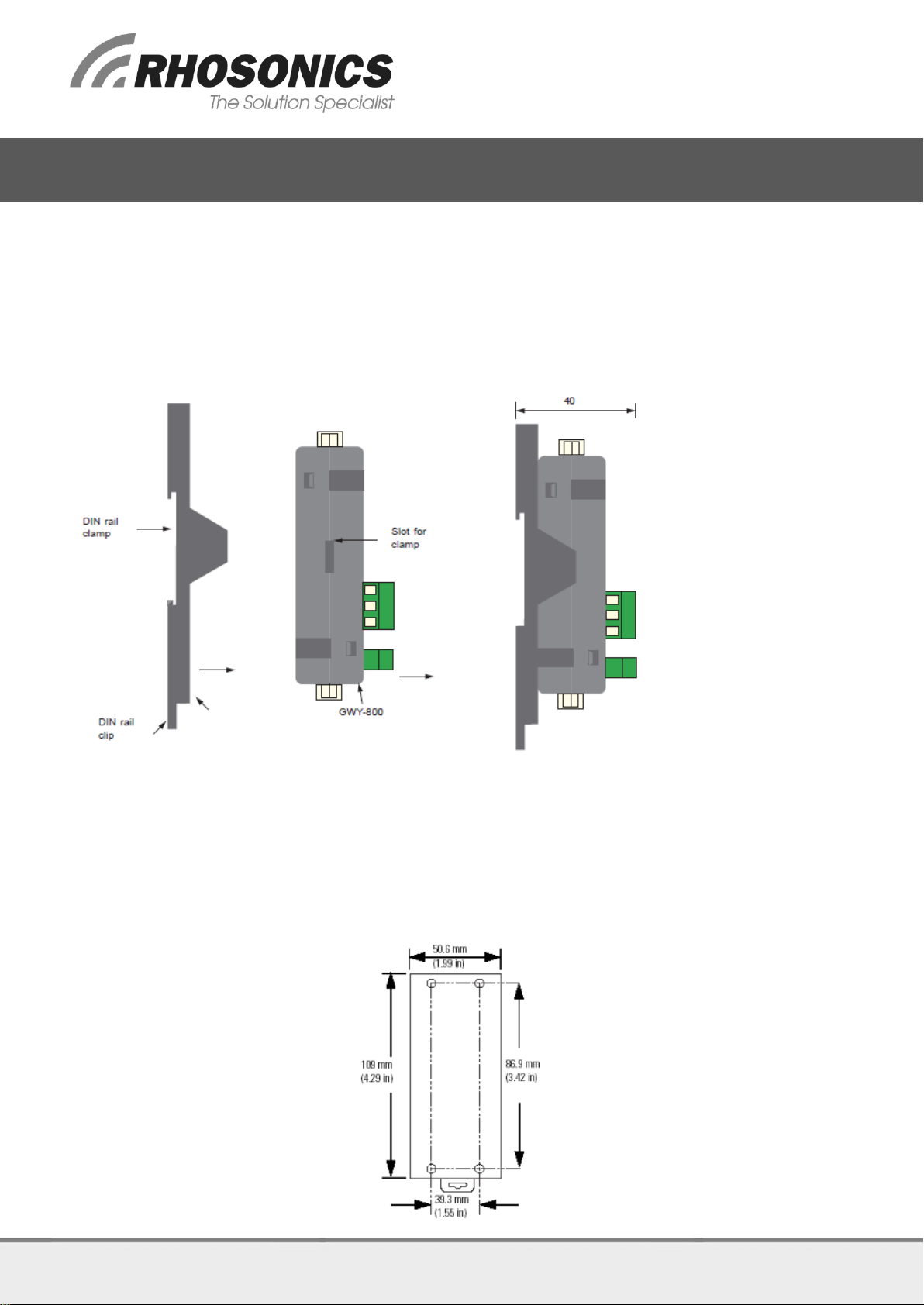
Following drawing shows how to attach the DIN rail plate to the unit:
Follow instructions given below:
1. Attach the DIN rail plate to the unit using the clamps on the DIN rail plate.
2. Pull out the clip of the plate.
3. Put the unit on the DIN rail.
4. Push the clip in to secure the unit on the DIN rail.
GWY-800-B unit is shipped with a separate DIN rail plate which has to be attached to the unit, if needed.
User can use the unit with or without the DIN rail plate. Following sketch shows mounting details of GWY-
800-B with the DIN rail plate.

9D1-031-D34-A HART to MODBUS RTU Manual (2) Revision A
HART TO MODBUS RTU MANUAL
2.3 Communication Port Details
2.3.1 HART connection
Configuration with 4-20mA connected to PLC/DCS
Configuration with 4-20mA directly connected to Gateway
2.3.2 Connection to PLC/DCS (digital)
RS-422/485 wiring: Modbus RTU Slave MJ2 to User System
RS-422/485 Connection
PLC1/COM1 GATEWAY
Signal Direction
USER CONNECTOR
Pin No.
Name
Pin No.
Name
1
TX+
pn
RX+
8
TX-
pn
RX-
4
RX+
pn
TX+
9
RX-
pn
TX-
5
GND*
pn
GND*
User can convert RS485 4 wire + Signal Ground system to a 2 Wire + Signal Ground system by shorting
following signals in the communication cable:

9D1-031-D34-A HART to MODBUS RTU Manual (2) Revision A
HART TO MODBUS RTU MANUAL
RS-232 wiring: Modbus RTU Slave MJ2 to User System
RS-232 Connection
PLC1/COM1 GATEWAY
Signal Direction
USER CONNECTOR
Pin No.
Name
Pin No.
Name
2
TXD
pn
RX
3
RXD
pn
TX
5
GND*
pn
GND*
CMOS wiring: Modbus RTU Slave MJ2 to User System
CMOS Connection
PLC1/COM1 GATEWAY
Signal Direction
USER CONNECTOR
Pin No.
Name
Pin No.
Name
7
TXD
pn
RX
3
RXD
pn
TX
5
GND*
pn
GND*
* Note: If user has attached shield to Earth on Device end, leave the shield open on Gateway end. If user
has connected shield to Signal Ground on Device end, connect shield to Signal Ground on Gateway end.
A and B are polarity insensitive. Twisted pair cable should be used for Rs485 Network.
2.4 LED Status
There are 3 LEDs for status indication.

9D1-031-D34-A HART to MODBUS RTU Manual (2) Revision A
HART TO MODBUS RTU MANUAL
LEDs status:
LED
PLC1
Yellow
OFF
No data receive on PLC port
ON / Flashing
COM1 / PLC1 side communication OK
OK
Green
OFF
Green OFF No Firmware
Fast Flashing
Polling HART Devices
ON
Device OK
PASS THROUGH
Not used!
2.5 Settings Modbus RTU Slave on MJ2
2.6 MODBUS readable data tables
2.6.1 Float Data (2 Words)
MODBUS Address
Dynamic Variable Value
400001
Primary Variable
400003
Secondary Variable
400005
Ternary Variable
400007
Quaternary Variable
2.6.2 Binary Data (1 Word)
MODBUS Address
Byte 1
Byte 0
Value
400009
X
Status
400010
6 bits
Extended Device type
400011
Device ID (Serial Number)
400012
X
Baud Rate
9600 bps
Start Bit
1
Data Bit
8
Parity
EVEN
Stop Bit
1
Device Address
1
Data Type
4 (holding registers)
Time Out
3000ms
Scan Rate
3000ms

9D1-031-D34-A HART to MODBUS RTU Manual (2) Revision A
HART TO MODBUS RTU MANUAL
2.6.3 Background MODBUS DATA
Dynamic Variables
The dynamic variables can be assigned to the following data (device variables)
No.
Device variable Value
0
Concentration 1
1
Concentration 2
2
Sound speed (m/s)
3
Temperature (°C)
4
SG X 1000
5
Acoustic Impedance ZL(kRayl)
6
Solids (g/l)
7
Power Liquid Echo PLE (dB)
Changing the assignment of the dynamic variables can be done by the service app or via HART (see model
dependent user manual).
Status
Status bits give a HART standardized error handling
Bit Mask
Definition
0x80
Device Malfunction –The device detected a serious error or failure that compromises
device operation.
0x40
Configuration Changed –An operation was performed that changed the device’s
configuration.
0x20
Cold Start –A power failure or device reset has occurred
0x10
More Status Available –More status information is available (HART)
0x08
Loop current Fixed –The Loop current is being held at a fixed value and is not
responding to process variations.
0x04
Loop Current Saturated –The Loop Current has reached its upper (or lower) endpoint
limit and cannot increase (or decrease) any further.
0x02
Non-Primary Variable Out of Limits –A Device Variable not mapped to the PV is
beyond its operating limits.
0x01
Primary Variable Out of Limits –The PV is beyond its operating limit.
Extended device type
Rhosonics extended device type is 0xE35D. The converter only responds the 14 least significant bits and will
reply 0x235D.
Bit
15
14
13
12
11
10
9
8
7
6
5
4
3
2
1
0
1
1
1
0
0
0
1
1
0
1
0
1
1
1
0
1
0xE35D
X
X
1
0
0
0
1
1
0
1
0
1
1
1
0
1
0x235D
Device ID (Serial number)
Device ID consists of 3 bytes. For example if the serial number is: 0002750 (0x 0A BE)
The data will be spread over 2 MODBUS addresses as follows.
MODBUS Address
Byte 1
Byte 0
Value
400011
0x00
0x0A
Device ID (Serial Number)
400012
0xBE
-
Table of contents
Popular Gateway manuals by other brands

ZyXEL Communications
ZyXEL Communications P-2304R-P1 Series user guide

Moeller
Moeller CM4-505-GV1 Hardware and engineering

Donaldson
Donaldson iCue Sensor Integrated Gateway Installation, operation and maintenance manual

RTA
RTA 460ETCBMS-NNA1 Product user guide

Comark
Comark RF500 System manual

Alcatel-Lucent
Alcatel-Lucent OmniAccess 8550 brochure