Gutermann ALPHA Instruction Manual

Safety Guidelines
&
Installation Manual
Language: English
Version: 1.4

2 I 19
Table of Contents
1Indications for Use.......................................................................................................... 3
1.1 Symbols.................................................................................................................. 3
1.2 Safety...................................................................................................................... 4
1.3 Intended Use........................................................................................................... 4
2Delivery Contents........................................................................................................... 5
3Mechanical Installation................................................................................................... 6
3.1 Safety Precautions.................................................................................................. 6
3.2 Directions for the ALPHA ........................................................................................ 6
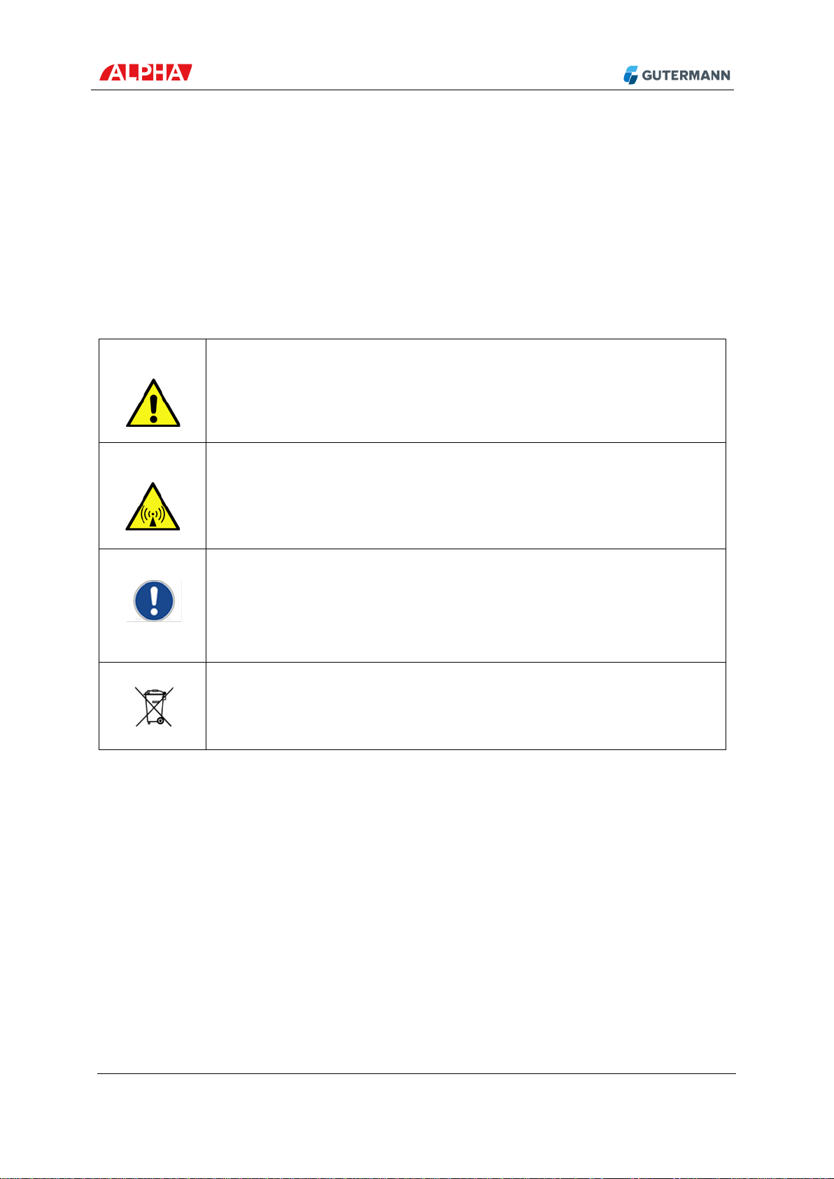
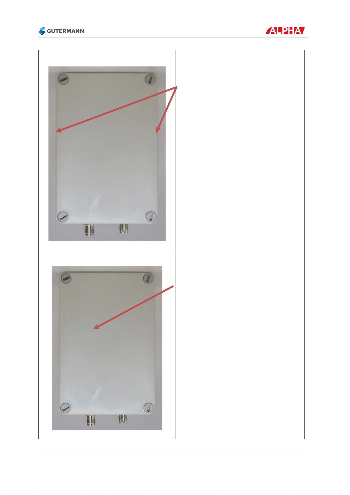
3.2.1 SIM Card.......................................................................................................... 7
3.2.2 Tool setting via pushbutton and LED indication................................................ 8
3.2.3 Mounting the ALPHA........................................................................................ 9
3.3 Directions for the Power Supply .............................................................................11
3.4 Directions for External Antennas............................................................................12
3.4.1 Directional Antenna YA9-11............................................................................12
3.4.2 Omnidirectional Antenna XL-900-3LW ............................................................13
4Technical Data..............................................................................................................14
4.1 Mechanical Dimensions .........................................................................................14
4.2 Used Radio Frequencies........................................................................................15
4.3 Battery....................................................................................................................16
4.4 Pin Assignment......................................................................................................16
4.4.1 Power Connector ............................................................................................16
4.4.2 Antenna Connector 1 to 3 ...............................................................................16
4.5 External Antenna....................................................................................................16
5Storage and Transport ..................................................................................................17
6Disposal........................................................................................................................17
7Imprint...........................................................................................................................17
8Conformity.....................................................................................................................18
9Important Information....................................................................................................19

3 I 19
1 Indications for Use
It is essential to read the operating instructions carefully and completely before using the first
time the equipment and software. They contain important information on safety, installation
and use. Keep these instructions in a safe place.
1.1 Symbols
Warning of dangerous situations that can cause injury and
damage to the devices.
Warning of non-ionising electromagnetic radiation.
Important notes and tips are a sign Info provided. Follow
these guidelines.
Never put in your household waste bin.

4 I 19
1.2 Safety
The operating and maintenance personnel must read the instructions carefully
before using the equipment. Knowing all the information contained therein - in
particular the warning and safety instructions - is needed to safely operate the
equipment, and to protect yourself and others against possible dangers. Ignoring the
warning, safety and operating instructions can result in injury, damage, or a considerable
shortening of the equipment life time. Do not make any changes or alterations to our
products.
The ALPHA contains a rechargeable battery. The battery/cells must not be removed from the
ALPHA, must not be short-circuited, physically damaged or exposed to heat, fire or water.
Follow the transport stipulations of the carrier (IATA-DGR, IMDG-Code, ADR, RID) when
returning an ALPHA to Gutermann. To protect the battery, the ALPHA must be recharged
every 6 months. For questions concerning replacing the battery, please contact your
Gutermann distributor.
When using the software or the equipment, make sure you adhere to any applicable
regulations, in particular traffic regulations.
1.3 Intended Use
ALPHA products, hardware, software, and accessories are exclusively intended for industrial
use and exclusively intended for leak detection on water pipes of the public water supply. In
particular, these products are not intended to be used on waste water and gas pipes.
Gutermann is not liable for any damages caused by misuse, improper operation, and as a
result of non-compliance with safety instructions and warnings.

5 I 19
2 Delivery Contents
The ALPHA System contains the following components:
ALPHA V2: Communication between loggers and repeaters
Solar panel: Recharges the battery of the ALPHA
Power cord: For the connection between the ALPHA and the solar panel
Fastening material: For fastening the ALPHA and the solar panel
External antenna (optional): For enhanced data transmission

6 I 19
3 Mechanical Installation
ZONESCAN ALPHA is the data gateway for HISCAN and ZONESCAN 820 permanent
monitoring systems. Especially when in use in conjunction with ZONESCAN 820 system,
which is spread out over a larger area, it is recommended to place the ALPHA at the highest
position available in order to ensure the best radio connection possible.
3.1 Safety Precautions
You must ensure that there is adequate safety present when working at great
heights.
Use additional safety to prevent tools, ALPHA or accessories from falling or create
a safety area on the ground.
Use protective gloves to prevent cuts from sharp edges.
3.2 Directions for the ALPHA
The device may only be installed by trained personnel.
Cable connectors are sealed against water only if the cable is connected. Seal with
a plug if unused. Tighten connectors correctly to ensure good contact and sealing.
No tools necessary – finger-tight fastening is adequate.
For your own convenience and to prevent ingress of moisture, open the ALPHA
only in clean and dry conditions such as an office. Insert the SIM card and test
internet connection to prevent necessitiy to re-open the ALPHA in the field.
Before reclosing the ALPHA the seal and the seal face has to be cleaned and
checked for damages. Damaged seals must be replaced in order to ensure
tightness.

7 I 19
3.2.1 SIM Card
Open the ALPHA carefully. The SIM card slot is located at the top of the device. Place the
SIM card as shown and insert it into the slot:
Before closing the ALPHA, check the seal. Remove any dirt and exchange it if damaged.
Close the lid and fasten the screws tightly.

8 I 19
3.2.2 Tool setting via pushbutton and LED indication
The device is equipped with a push button and one LED that can indicate red and green.
This allows to enforce some fundamental settings.
•Switch the device into the sleep mode and wake it up from the sleep mode:
In the sleep mode nearly all functions of the device are disabled and the power
consumption is reduced to the minimum. This mode is designated for longer periods
of non-usage. The only available function is to be prepared for a wake-up.
To enforce the device to go into the sleep mode press the push button for more than
two seconds. The LED will indicate the transition by flashing five times in red.
If the dvice is in the sleep mode and you intend to wake it up also push the button for
at least 2 seconds. The LED will indicate the transition by flashing five times in green.
See also chapter 5 Storage and transportation
•Sending a test e-mail:
To enforce the sending of a test e-mail push the button two times less than one
second. The LED will continuously be red during this test. Thereafter it will flash five
times red when the test failed or five times green when the test was successful.
The LED will go off and on in between the test (without flashing), therefore wait for
at least 2 minutes before trying another test!

9 I 19
3.2.3 Mounting the ALPHA
On the back side of the ALPHA there is a metal mounting plate which enables secure
installation also to round objects.
Make sure to use mounting material suitable for the environment. To ensure
redundancy, it is mandatory to use always two fastening elements for the ALPHA
housing.
Do not use the ALPHA if it is damaged.
Mount the ALPHA with its connectors oriented towards the bottom.
No metal parts on or near the front, the top or the sides of the housing – they would
interfere with the various antennas.
When using stickers, make sure to use non-metallic materials and colours only, in
order to avoid interference with radio- or mobile connection.
GPS antenna location
Internal on the top
GPS antenna provision
Free line of sight to the satellites in the sky
is optimal

10 I 19
Modem antenna location
Internal on both sides
Modem antenna provision
Free line of sight to the base station is
optimal
Internal radio antenna location
Internal antenna below the lid
Internal radio antenna provision
Free line of sight to the repeater is optimal

11 I 19
3.3 Directions for the Power Supply
The main power supply for the ALPHA is a solar panel which is used to charge the internal
battery.
If an alternative power supply (12VDC ±10% / 4W) is used, it must be installed by a
skilled electrician in compliance with local regulations.
At the back side of the solar panel there is a metal mounting plate similar to that of the
ALPHA.
Make sure to use mounting material suitable for the environment. To ensure
redundancy, it is mandatory to use always two fastening elements for the solar
panel.
Panel orientation should be chosen so that it gets as much sun as possible
especially under bad conditions like in winter. Also take shadows of buildings, trees
etc. into consideration.
Slightly incline the panel so that rain can clean it and there is the lowest
accumulation of dirt or snow.
Cable connector should be at the bottom.

12 I 19
3.4 Directions for External Antennas
3.4.1 Directional Antenna YA9-11
This Yagi type antenna is a directional antenna with a main horizontal distribution at +/- 30 °
of the direction it is pointed to. It is best used, if the ALPHA is placed outside the installation
area of loggers that should be covered.
Mounting clamp fits poles up to 50 mm. Always use both clamps and securely
tighten the screws.
The little staves should be oriented vertically for correct polarisation.
Sample installation with solar panel and Yagi

13 I 19
3.4.2 Omnidirectional Antenna XL-900-3LW
This 70 cm rod antenna is an omnidirectional antenna. It is best used, if the ALPHA is placed
within the installation area of loggers which should be covered.
Mounting clamp fits poles up to 50 mm. Always use both clamps and securely
tighten the screws.
The rod should be oriented vertically for correct polarisation.
Sample installation with solar panel and rod antenna

14 I 19
4 Technical Data
4.1 Mechanical Dimensions
Parameter
Comment
min.
typ.
max.
Unit
Size
Length
Without connector
152
mm
Width
102
mm
Height
With mounting plate
95
mm
Others
Weight
1.3
kg
Operating temperature
-30
70
°C
Protective class
Connector inserted
IP67

15 I 19
4.2 Used Radio Frequencies
System
Frequency
Emitting Power
Gutermann Radio (internal)
869.525 MHz
20 mW
Gutermann Radio (external)
869.525 MHz
Up to 500 mW (*)
UMTS
Band I
250 mW
UMTS
Band II
250 mW
UMTS
Band V
250 mW
UMTS
Band VI
250 mW
UMTS
Band VIII
250 mW
GSM
Band 850
2 W
GSM
Band 900
2 W
GSM
Band 1800
1 W
GSM
Band 1900
1 W
LTE
1
200 mW
LTE
2
200 mW
LTE
3
200 mW
LTE
4
200 mW
LTE
5
200 mW
LTE
7
200 mW
LTE
8
200 mW
LTE
12
200 mW
LTE
18
200 mW
LTE
19
200 mW
LTE
20
200 mW
LTE
28
200 mW
(*) Depending on antenna gain

16 I 19
4.3 Battery
Type
LiFePO
4
Number of cells
4
Voltage
3.3 V / 3.6 V (nominal / charge)
Capacity
33 Wh / 10 Ah
Charging temperature
-30 °C – 55 °C
4.4 Pin Assignment
4.4.1 Power Connector
M8 Connector
Pin
Signal
1
+12V
DC
/ 4W Input
3
NC
4
Ground
4.4.2 Antenna Connector 1 to 3
Connector: RP-TNC; Plug (IP67 connected)
RP-TNC
Connector
Pin
Signal
1
case
1
Signal
case
Ground
4.5 External Antenna
Impedance: 50Ω
3 1
4

17 I 19
Antenna gain: 11dBi max.
Polarisation: linear; vertical
Minimum safe distance: 0.2 m
5 Storage and Transport
In order to avoid unwanted radio transmissions and prevent battery depletion, the ALPHA
must be set to sleep mode for storage and transportation.
In sleep mode, the ALPHA will listen on the Gutermann radio every 30 seconds, but not
transmit. The modem will also stay switched off.
In order to enter sleep mode, open the ALPHA, press the button at the top and keep it
pressed for 2 seconds. The LED will confirm entering sleep mode with 5 red flashes.
The ALPHA will enter sleep mode on its own if over the course of two days there is no power
supply connected and no SIM card inserted.
6 Disposal
Never put electrical appliances in a household waste bin. Always collect them separately and perform an
environmentally friendly recycling. When disposing of electrical appliances always comply with national
and regional waste disposal regulations. If an orderly disposal of our products is not possible, send the
unit to us. We dispose of our products environmentally friendly. Address see below.
7 Imprint
Gutermann Technology GmbH
Gottlieb-Daimler-Str. 10
88214 Ravensburg, Germany
Subject to changes
Tel: +49 751 3590 1682
Fax: +49 751 3590 1699
www.gutermann-water.com
info@gutermann-water.com

18 I 19
8 Conformity
This device contains licence-exempt transmitter(s)/receiver(s) that comply with Innovation,
Science and Economic Development Canada’s licence-exempt RSS(s). Operation is subject
to the following two conditions:
1. This device may not cause interference.
2. This device must accept any interference, including interference that may cause
undesired operation of the device.
L’émetteur/récepteur exempt de licence contenu dans le présent appareil est conforme aux
CNR d’Innovation, Sciences et Développement économique Canada applicables aux
appareils radio exempts de licence. L’exploitation est autorisée aux deux conditions
suivantes :
1. L’appareil ne doit pas produire de brouillage;
2. L’appareil doit accepter tout brouillage radioélectrique subi, même si le brouillage est
susceptible d’en compromettre le fonctionnement.
This equipment has been tested and found to comply with the limits for a Class B digital
device, pursuant to part 15 of the FCC Rules. These limits are designed to provide
reasonable protection against harmful interference in a residential installation. This
equipment generates, uses and can radiate radio frequency energy and, if not installed and
used in accordance with the instructions, may cause harmful interference to radio
communications. However, there is no guarantee that interference will not occur in a
particular installation. If this equipment does cause harmful interference to radio or television
reception, which can be determined by switching the equipment to sleep mode and wake it
up from sleep mode , the user is encouraged to try to correct the interference by one or more
of the following measures:
•Reorient or relocate the receiving antenna.
•Increase the separation between the equipment and receiver.
•Consult the dealer or an experienced radio/TV technician for help.
FCC NOTICE: To comply with FCC part 15 rules in the United States, the system must be
professionally installed to ensure compliance with the Part 15 certification.
It is the responsibility of the operator and professional installer to ensure that only certified
systems are deployed in the United States.
FCC / ISED RF Exposure: To comply with the RF exposure requirements for General Use/
Uncontrolled Exposure this device with it's antenna(s) must be fixed mounted.
Changes or modifications to this equipment not expressly approved may void the user’s
authority to operate this equipment.

19 I 19
9 Important Information
Please draw your attention to all warnings and information in the manual and on the
products. By using this product, you acknowledge that you are aware of and have read the
warnings and information provided in the manual.
Always clean the sensors and mechanical accessories with a clean towel after use
before stowing them away in the carry case.
Table of contents