Ribitech KG130 User manual

KG130
ISTRUZIONI D’USO
OPERATING INSTRUCTIONS
BEDIENUNGSANLEITUNG
INSTRUCTIONS D’EMPLOI
INSTRUCCIONES PARA EL USO
INSTRUÇÕES DE USO
GEBRUIKSAANWIJZING
BRUGSANVISNING
ATTENZIONE! Prima di usare l’utensile, leggete attentamente le istruzioni per l’uso.
CAUTION! Before starting the tool, read the operating instructions carefully.
ACHTUNG! Vor Inbetriebnahme Bedienungsanleitung lesen.
ATTENTION! Avant la mise en service, lire scrupuleusement les instructions d’emploi.
ATENCION! Antes de usar el aparato, leer atentamente las instrucciones de empleo.
ANTENÇÃO! Anted de usar o aparelho, ler com antenção as instruções de uso.
LET OP! Lees de gebruiksaanwijzing heel goed door voordat u het geredschap gebruikt.
ADVARSEL! Gennemlaes nedenstående sikkerhedsforskrifter nøje,inden De anvender vaerktøjet.
Cod. 9P0104
IP55

1) CAVO
2) TERRA
3) CONDENSATORE
4) FILO SOSTITUTIVO
5) FILO PRINCIPALE
6) FILO COMUNE
7) MORSETTO
1) CABLE
2) EARTH
3) CAPACITOR
4) VICE WIRE
5) MAIN WIRE
6) COMMON WIRE
7) CONNECTOR
1) CABLE
2) TERRE
3) CONDENSATEUR
4) VICE-FIL
5) FIL PRINCIPAL
6) FIL COMMUNE
7) CONNECTEUR
1) KABEL
2) ERDE
3) KONDENSATOR
4) ERSATZ-DRAHT
5) HAUPT-DRAHT
6) NORMAL-DRAHT
7) KLEMME
1) CABLE
2) TIERRA
3) CONDENSADOR
4) VICE-ALAMBRE
5) ALAMBRE PRINCIPAL
6) ALAMBRE COMUN
7) BORNE
Fig. 1
2
KG130 98 90 290 140 112 190 37 1/2" 1/2" 74 170 320 150 195 10.6
3/4" 3/4"
ABCD EFGL1L2NLM Kg.
DNA DNH
H1H2
Dimensioni mm
Dimensions mm
TIPO
TYPE
Imballo mm
Packing mm
Peso
Weight
Fig. 4
WEC KG130 4-02-2008 11:09 Pagina 2

CAPOT VENTILATEUR
VENTILATEUR
BORNIER
CONDENSATEUR
VIS
FLASQUE A MOTEUR
RONDELLE ELASTIQUE
ROULEMENT
CARCASSE STATOR
BOBINE
BOITIER PLASTIQUE
DE CONDENSATEUR
ARBRE + INDUIT
CLAVETTE
CACHE POUSSIERE
SUPPORT
JOINT OR
TURBINE
JOINT MECANIQUE
CORPS DE POMPE
VIS
BOUCHON
CIR CLIPS
RONDELLE
INTERRUPTOR
PEZZI DI RICAMBIO SPARE PARTS ERSATZTEILE PIEZAS DE REPUESTO PIÈCES DÉTACHÉES Q.TY
COPRIVENTOLA
VENTOLA
MORSETTIERA
CONDENSATORE
TIRANTE
CALOTTA
ANELLO ELASTICO
CUSCINETTO
CARCASSA CON
STATORE AVVOLTO
COPRIMORSETTIERA
ALBERO + ROTORE
CHIAVETTA
PARASPRUZZI
SUPPORTO
ANELLO OR
GIRANTE
TENUTA MECCANICA
CORPO POMPA
VITE SUPPORTO
TAPPO
ANELLO SEEGER
RONDELLA
INTERUTTORE
FAN COVER
FAN
BOARD
CAPACITOR
TIE-ROD
DRIVING CAP
SPLIT RING
BEARING
CASING WITH
WOUND STATOR
BOARD COVER
SHAFT + ROTOR
KEY
DROP GUARD
MOTOR BRACKET
GLAND O-RING
IMPELLER
MECHANICAL SEAL
PUMP BODY
BRACKET SCREW
PLUG
SNAP RING
WASH
SWITCH
1
2
3
4
5
6
7
8
9
10
11
12
13
14
15
16
17
18
19
20
21
22
23
LAUFRADSCHUTZ
LAUFRAD
KLEMMBRETT
KONDENSATOR
ZUGSTAB
KAPPE
KOLBENRING
LAGER
GEHÄUSE MIT
GEWICKELTEM
STATOR
KLEMMBRETT-
SCHUTZ
WELLE + ROTOR
SCHLÜSSEL
SPRITZBLECH
HALTER
O- RING
LÄUFER
MECHANISCHE
DICHTE
PUMPENKÖRPER
STÜTZSCHRAUBE
STOPFEN
SEEGERRING
SCHEIBE
SCHALTER
CUBREIMPULSOR
IMPULSOR
TABLERO DE BORNES
CONDENSADOR
TIRANTE
CASQUETE
ANILLO ELASTICO
COJINETE
ARMAZON CON
STATOR ARROLADO
CUBRETABLERO
EJE + ROTOR
CHAVETA
PARASALPICADURAS
SOPORTE
ANILLO OR
ROTOR
SELLADO MECANICO
CUERPO BOMBA
TORNILLO DE SOPORTE
TAPON
ANILLO SEEGER
RONDELA
INTERRUPTOR
1
1
1
1
4
1
1
2
1
2
1
1
1
1
1
1
1
1
1
3
1
3
Fig. 5
WEC KG130 4-02-2008 11:09 Pagina 3

CAP. 1 DATI IDENTIFICAZIONE DEL FABBRICANTE
E DELLA MACCHINA
1.1. Nome e indirizzo del fabbricante
Ribimex Italia s.r.l.
Via Igna
I-36010 Carrè (Vi)
1.2 Identificazione della macchina
A) Denominazione: Elettropompa
B) Modello: KG 130
C) Numero di serie e anno di costruzione: Vedi
targhetta dati sull’elettropompa
IP 55 CE
CAP. 2 DESCRIZIONE DELLA MACCHINA
2.1 Descrizione generale
Le elettropompe periferiche a palette radiali sono molto
similari tra loro dal punto di vista funzionale e
costruttivo. Si differenziano per:
- Voltaggio = V
- Potenza = kW
- Portata = l/min.
- Prevalenza = m
- Peso e dimensioni = kg; C D F (Cap. 14.1)
2.2 Caratteristiche tecnico-costruttive
Le elettropompe della serie KG 130 sono state
progettate seguendo le seguenti normative:
A) Rischi di natura meccanica (EN 292-1 e EN 292-2).
B) Rischi di natura elettrica (EN 292-1 e EN 292-2; CEI
61-69).
C) Rischi di varia natura (CEE 98/37).
I componenti elettrici e relativi circuiti installati
sull’elettropompa sono a norme CEI 44-5.
CAP. 3 AVVERTENZE GENERALI DI SICUREZZA
La mancata osservanza delle avvertenze e/o la
manomissione dell’elettropompa solleverà la Ribimex
Italia s.r.l. da qualsiasi responsabilità in caso di
incidenti a persone e animali, danni a cose o
all’elettropompa stessa, determinando inoltre la perdita
totale della garanzia sul prodotto.
3.1 Misure di prevenzione
A) L’utente deve assolutamente osservare le norme
antinfortunistiche in vigore. Inoltre dovrà seguire le
indicazioni riportate ai capitoli seguenti.
B) Prima di effettuare qualsiasi operazione
sull’elettropompa, ricordarsi sempre di togliere
l’alimentazione elettrica disinserendo la spina.
C) Non spostare per nessun motivo l’elettropompa
durante il suo funzionamento.
D) Prima di utilizzare l’elettropompa controllare sempre
che il cavo di alimentazione elettrica, come anche
tutti gli altri dispositivi, siano perfettamente integri.
E) Prima di avviare l’elettropompa assicurarsi di non
essere a piedi nudi, di non avere le mani bagnate o
peggio ancora di essere immersi, anche
parzialmente, nell’acqua.
F) Le elettropompa prodotte da Ribimex Italia s.r.l.
sono costruite in modo tale che tutte le parti in
movimento sono protette da carenature. Con
l’elettropompa in funzione non rimuovere per alcun
motivo tali parti.
G) E’ molto importante che la presa di corrente a cui è
collegata l’elettropompa non sia a portata del getto
d’acqua, pioggia, altri liquidi o agenti atmosferici in
genere.
CAP. 4 USO PREVISTO E NON PREVISTO
4.1 Uso previsto
Le elettropompe della serie KG 130 sono state
progettate per travasare gasolio da fusti, serbatoi e
cisterne. Sono quindi indispensabili laddove sia
necessario travasare o movimentare gasolio, come ad
esempio : fattorie, cantieri edili e navali, industrie ed
abitazioni private.
4.2 Uso non previsto
A) Pompaggio di acqua di mare, acqua sporca, acqua
con corpi solidi in sospensione, sabbia, parti
abrasive o corrosive in genere.
B) Pompaggio liquidi con temperature superiori ai 90° C.
C) Pompaggio di liquidi alimentari.
D) Pompaggio di liquidi esplosivi, infiammabili e
comunque pericolosi
CAP. 5 MOVIMENTAZIONE E TRASPORTO
5.1 Disimballo
Se l’imballo non dovesse risultare in buono stato una
volta estratta l’elettropompa, verificare che questa non
abbia subito danni durante il trasporto o il
maneggiamento. Eventuali rotture o anomalie
dovranno essere comunicate al rivenditore entro e non
oltre 8 giorni dalla consegna.
ATTENZIONE: prima di installare e usare
l’elettropompa, verificare sulla targa che il modello e le
sue caratteristiche siano quelle richieste.
5.2 Movimentazione, disinstallazione e trasporto
Le ridotte dimensioni e pesi dell’elettropompa non
creeranno particolari difficoltà; nel trasportarla si
raccomanda comunque di:
A) Non muovere mai per nessun motivo l’elettropompa
senza aver prima staccato la spina dalla presa o
comunque aver interrotto l’alimentazione elettrica.
B) Svitare e quindi togliere i tubi di mandata e di
aspirazione.
C) Svitare i bulloni o le viti con cui l’elettropompa è
stata ancorata.
D) Avvolgere il cavo di alimentazione all’elettropompa.
E) Non trasportare o trascinare l’elettropompa tramite il
cavo di alimentazione.
CAP. 6 PREPARAZIONE ALL’UTILIZZO
6.1 Collegamento elettrico alla rete
Prima di collegare l’elettropompa alla rete di
alimentazione, verificare che l’impianto sia adatto a
I
4

sopportare i consumi richiesti dal motore (vedi dati
sulla targhetta).
Inoltre è indispensabile che l’impianto sia munito di
protezione (salvavita) di max. 30 mA.
Le elettropompe già fornite di cavo e spina, devono
essere collegate ad una presa di corrente adatta per
presa SCHUKO, con doppio contatto di terra. Per
nessun motivo tagliare e/o sostituire la spina fornita di
serie. Fornirsi eventualmente di adattatore.
Se il cavo di alimentazione è danneggiato, esso deve
essere sostituito dal costruttore o dal suo servizio
assistenza tecnica o comunque da persona con
qualifica similare, in modo da prevenire
ogni rischio.
6.1 A L’apparecchio deve essere posto in modo che la
spina sia accessibile.
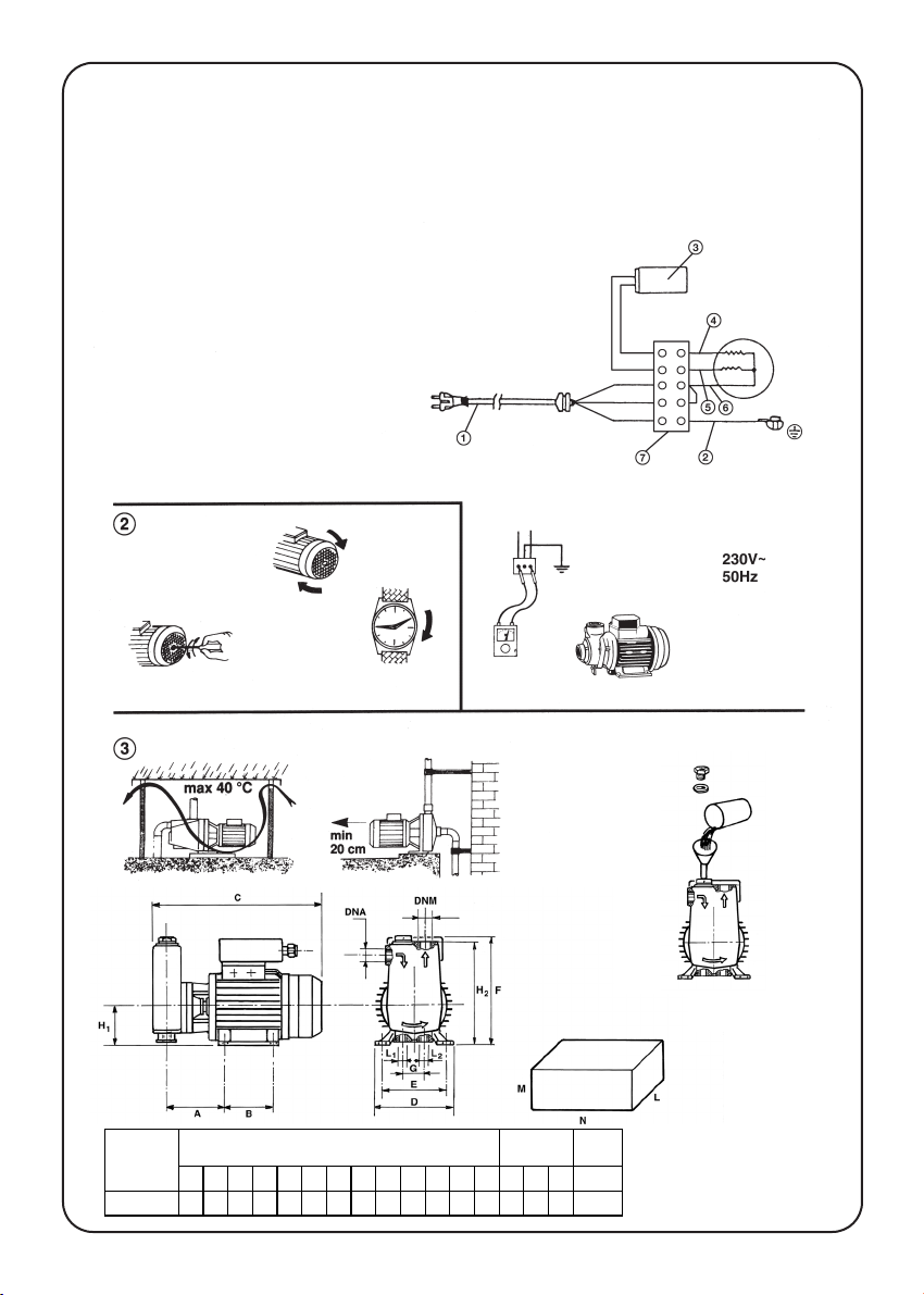
6.2 Verifica di funzionamento
Prima di installare l’elettropompa è consigliabile fare
una prova del motore a vuoto. Facendo molta
attenzione che tutti i contatti elettrici siano ben sigillati,
far partire l’elettropompa osservando la ventola di
raffreddamento posizionata sul retro del motore (Fig.
2). Verificare che il senso di rotazione sia quello
indicato dalla freccia impressa sul corpo pompa.
CAP. 7 INSTALLAZIONE
L’elettropompa è un apparecchio elettrico e come tale
va posizionato in un luogo protetto da intemperie (sole,
pioggia, neve, etc). Inoltre non deve essere esposta a
getti d’acqua e il luogo in cui si trova deve essere
adeguatamente ventilato.
7.1 Posizionamento fisso
Il posizionamento deve essere effettuato su di una
superficie perfettamente piana e solida. Nello scegliere
la posizione, fate attenzione e rispettate le distanze
minime previste da muri o pareti (Fig. 3) per agevolare
eventuali operazioni di uso e manutenzione. E’
importante che l’elettropompa sia posizionata il più
vicino possibile alla fonte di gasolio (max. 6 m di
distanza).
7.2 Installazione
A) Utilizzare tubazioni metalliche o di materiale plastico
ad alto grado di resistenza.
B) Se si utilizzano tubi flessibili in aspirazione o in
mandata, evitare di piegarli per non causare
strozzature.
C) Le tubazioni devono essere di diametro adeguato
alle bocche dell’elettropompa, dotate di manicotti
filettati che dovranno essere sigillati con sigillanti
adeguati.
D) Se il tubo di aspirazione è più lungo di 4 m., è
necessario che questo abbia un diametro superiore
a quello della bocca di aspirazione. Inoltre si
consiglia di installare una valvola di fondo munita di
filtro.
E) All’uscita del tubo di mandata è consigliabile
montare una valvola a sfera.
F) Fissare i tubi di aspirazione in modo che il peso e le
vibrazioni non gravino sull’elettropompa.
CAP. 8 UTILIZZO E MESSA IN FUNZIONE
8.1 Messa in funzione
A) Prima di tutto assicurarsi nuovamente che i contatti
elettrici siano ben chiusi e sigillati, che il cavo di
alimentazione non abbia subito danni durante
l’installazione e poi chiudere la saracinesca in
mandata.
B) Procedere al riempimento dell’elettropompa tramite
l’apposito foro di riempimento e rimuovere il tappo
(Fig. 4). Una volta riempito completamente il corpo
pompa e il tubo di aspirazione, chiudere il foro di
riempimento (Fig. 4).
C) Inserire la spina nella presa di corrente o azionare
l’interruttore di alimentazione. Prima di effettuare
questa operazione, fare attenzione a quanto
descritto al cap. 3 par. 3.1.
D) L’elettropompa comincerà quindi a lavorare.
8.2 Avvertenze importanti
A) Evitare di far lavorare l’elettropompa a secco (senza
gasolio all’interno del corpo pompa).
B) Il funzionamento prolungato con la saracinesca in
mandata chiusa può creare seri danni.
C) In caso di mancanza di corrente elettrica in rete, è
consigliabile staccare la spina dalla presa o
disinserire l’interruttore.
8.3 Arresto
A) Si consiglia di chiudere la saracinesca in mandata
prima di spegnere l’elettropompa. Questo eviterà
eventuali colpi d’ariete. Quindi spegnere
l’interruttore.
B) Se l’elettropompa non sarà usata per un periodo più
o meno lungo, si consiglia di scaricarla dal gasolio
presente nel corpo pompa.
CAP. 9 MONTAGGIO E SMONTAGGIO
L’elettropompa non ha parti accessorie staccate,
pertanto non necessita di alcun montaggio.
L’eventuale smontaggio dell’elettropompa deve essere
eseguito solo ed esclusivamente presso centri di
assistenza o da tecnici qualificati.
CAP. 10 MANUTENZIONE E RIPARAZIONE
10.1 Manutenzione
Qualsiasi operazione di manutenzione deve essere
eseguita solo dopo aver disinserito la spina elettrica.
L’elettropompa non necessita di particolari
manutenzioni all’interno, pertanto astenersi dallo
smontaggio della stessa. E’ comunque molto
importante che la parte aspirante e di mandata sia
sempre mantenuta perfettamente pulita e libera da
eventuali corpi ostruenti.
CAP. 11 RISCHI MECCANICI
11.1 Parti meccaniche soggette ad usura
A) La tenuta meccanica (Dis.5 pos.17) si può usurare
anche dopo un periodo relativamente breve,
soprattutto se sono stati pompati liquidi anche
leggermente abrasivi. Tale parte dovrà essere
I
5
WEC KG130 4-02-2008 11:09 Pagina 5

sostituita anche nel caso sia semplicemente
smontata per un’ispezione qualsiasi.
B) Cuscinetti (Dis. 5 pos.8)
C) Girante (Dis.5 pos.16)
ATTENZIONE : Le parti sopramenzionate dovranno
essere sostituite solo da tecnici qualificati o presso
centri di assistenza.Usare solo ricambi originali.
CAP. 12 SCHEDA DATI TECNICI DELLA MACCHINA
Caratteristiche costruttive del motore
Motore elettrico chiuso autoventilato a due poli, con
protezione IP55, classe di isolamento F. versione
monofase con motoprotettore termico incorporato e
condensatore perennemente inserito.
Caratteristiche costruttive della pompa
Corpo pompa: GHISA G 25
Supporto motore: GHISA G 25
Girante: OTTONE STAMPATO
Albero motore: ACCIAIO INOX
Tenuta meccanica: CARBONE CERAMICA
CAP. 13 INFORMAZIONI SULLA RUMOROSITÀ’
L’elettropompa in funzione con liquido all’interno del
corpo pompa non supera il valore di 70 db.
I
La pompa non gira.
INCIDENTI CAUSE RIMEDI
La pompa gira ma non eroga gasolio.
Il motoprotettore termico ferma
l’elettropompa per surriscaldamento.
1) Mancanza di alimentazione elettrica.
2) Albero bloccato.
1) L’aria nel corpo pompa non è
completamente spurgata.
2) La pompa aspira aria dal tubo di
aspirazione.
1) Alimentazione non conforme ai dati
di targa del motore.
2) Un corpo solido ha bloccato la
girante.
3) la pompa ha funzionato a secco o
con un rubinetto di mandata chiuso
per più di 15 min.
1) Svitare il tappo di carico con la pompa
in funzione e sfiatare completamente il
corpo pompa, quindi fissare
nuovamente il tappo.
2) Controllare che il tubo di aspirazione
sia ben raccordato e sigillato sulla
pompa. Verificare che il tubo di
aspirazione non abbia strozzature o
sifoni. Attenzione all’altezza max. di
aspirazione.
1) Controllare la tensione in rete.
2) Levare il tubo di aspirazione e
quindi rimuovere il corpo solido.
3) Fare raffreddare l’elettropompa e
quindi farla ripartire facendo
attenzione che durante detto
periodo non si sia danneggiata la
tenuta meccanica.
10.2 Ricerca guasti
Prima di riutilizzare l’elettropompa dopo un breve o lungo periodo di inattività è consigliabile verificare se l’albero gira liberamente. Tale
operazione si potrà eseguire inserendo un cacciavite nella feritoia ricavata sull’albero stesso (Fig. 2).
6
1) Controllare se c’è tensione nella
presa, e se la spina è ben inserita.
2) Togliere la spina elettrica dalla presa:
inserire il cacciavite sull’albero
motore (dalla parte della ventola) e
sbloccare ruotando il cacciavite.
WEC KG130 4-02-2008 11:09 Pagina 6

CHAP. 1 IDENTIFICATION DATA OF THE PRODUCER
AND THE MACHINE
1.1. Name and address of the producer
Ribimex Italia s.r.l.
Via Igna
I-36010 Carrè (Vi)
1.2 Identification of the machine
A) Denomination: Motor pump
B) Modell: KG 130
C) Serial number and construction year: see plate on
the motor pump
IP 55 CE
CHAP. 2 DESCRIPTION OF THE MACHINE
2.1 General description
The motor pumps with radial vanes are very similar for
what concerns function and manufacture. The
differences are in:
- Voltage = V
- Power = kW
- Capacity = I/min.
- Head = m
- Weight and dimensions = kg; C D F (Chap. 14.1)
2.2 Characteristics
The motor pumps KG 130 have been designed in
accordance with the following directives:
A) Mechanical risks (EN 292-1 and EN 292-2).
B) Electrical risks (EN 292-1 and EN 292-2; CEI 61-69).
C) Various risks (EEC 98/37).
The electrical components and the respective circuits
installed on the motor pump comply with CEI 44-5.
CHAP. 3 GENERAL SAFETY WARNINGS
The non-respect of the warnings and/or the breaking of
the motor pump will release Ribimex Italia s.r.l. from
whichever responsibility in case of accidents to
persons or animals and damages to things or the
motor pump itself. It will moreover cause the complete
loss of the guarantee on the product.
3.1 Preventive measures
A) The user should follow the accident prevention
measures in force. He should also follow the
indications given in the following chapters.
B) Before operating on the motor pump, always
disconnect the machine and cut off the feeding.
C) Don’t displace the motor pump while it is working.
D) Before using the motor pump always control that
the feeding cable, as well as the other devices, are
complete.
E) Before starting the motor pump make sure not to be
barefoot, with wet hands or even partially immersed
in water.
F) The motor pumps produced by Ribimex Italia s.r.l.
are manufactured with all the moveable parts
protected by fairings. Do not remove these parts
while the motor pump is working.
G) It is very important that the socket to which the
motor pump is connected is not in reach of water
jets, rain, other liquids or atmospherical agents in
general.
CHAP. 4 FORESEEN AND NOT FORESEEN USE
4.1 Foreseen use
The motor pumps KG 130 have been designed to pour
off diesel oil from drums, tanks and tankers. They are
useful where is necessary either pouring off or move
diesel-oil, for example :
farms, building and dockyard, industries and private
houses.
4.2 Not foreseen use
A) To pump salt water, dirty water, water with solid
bodies floating, sand, abrasive or corrosive parts.
B) To pump liquids with temperatures higher than 90° C.
C) To pump food liquids.
D) To pump explosive, inflammable or dangerous
liquids.
CHAP. 5 HANDLING AND TRANSPORT
5.1 Unpacking
After having removed the motor pump from the
packaging, check that it has not been damaged during
handling and transport. Possible breakings or
anomalies should be notified to the seller within 8 days
from the delivery.
CAUTION: before installing and using the motor pump
check on the plate that the model and its
characteristics are the requested ones.
5.2 Handling, disinstallation and transport
The motor pump has reduced dimensions and weight.
During the transport it is recommended:
A) Absolutely not to move the motor pump without
having unplugged the mains or cut off the feeding.
B) To unscrew and then remove the delivery and intake
tubes.
C) To unscrew the bolts or screws with which the motor
pump has been anchored.
D) To wind the feeding cable to the motor pump.
E) Not to trasport or drag the motor pump through the
feeding cable.
CHAP. 6 SETTING
6.1 Electrical connection
Before connecting the motor pump to the feeding net,
make sure that the plant is suitable for the
consumptions requested by the motor (see data on the
plate).
The plant should also be equipped with a protection of
max. 30 mA .
The motor pumps already equipped with cable and
plug should be connected to a socket suitable for the
SCHUKO plug with double grounding contact. Never
cut and/or replace the plug which is supplied. In case
provide yourself with an adaptor.
GB
7

If the cable is damaged, it has to be replaced by the
manufacturer or by its Service Center or in any case by
a qualified person , in order to avoid any risk.
6.1 A The tool has to be placed in a suitable way to
allow an easily reaching of the plug.
6.3 Functioning check
Before installing the motor pump make an idling check
of the motor. Make sure that all the electrical contacts
are well sealed, start the motor pump observing the
cooling vane on the back of the motor (Fig. 2). Control
that the sense of rotation is the one indicated by the
arrow on the body of the pump.
CHAP. 7 INSTALLATION
The motor pump is an electrical device and should
therefore not be exposed to the inclemency of the
weather (sun, rain, snow, etc). It should also not be
exposed to water jets and be placed in a correctly
ventilated place.
7.1 Fixed positioning
The pump should be placed on a perfectly flat and
solid surface. Carefully respect the minimum distances
foreseen for the walls (Fig. 3) to make possible
maintainance operations easier. The motor pump
should be placed as near as possible to the diesel oil
source (max. 6 m distance).
7.2 Installation
A) Use metallic tubes or plastic tubes with a high
degree of resistance.
B) If you use flexible delivery and intake tubes avoid
folding them in order not to cause throttlings.
C) The tubes should have a diameter suitable to the
openings of the motor pump, equipped with thread
muffs sealed with proper sealants.
D) If the intake tube is longer than 4 m., it should have
a diameter wider than that of the intake opening. It
is also advised to mount a suction valve with filter.
E) It is advised to mount a ball valve on the outlet of the
delivery tube.
F) Fix the inlet tubes so that weight and vibrations are
not loaded on the motor pump.
CHAP. 8 USE AND START
8.1 Start
A) Control once more that the electrical contacts are
well closed and sealed and that the feeding cable
has not been damaged during the installation and
then close the delivery gate.
B) Fill in the motor pump through the suitable filling
hole and remove the plug (Fig. 4). Once the body of
the pump and the inlet tube have been completely
filled in, close the filling hole (Fig. 4).
C) Insert the plug into the socket or operate the start
switch. Before carrying out this operation carefully
read Chap. 3 par. 3.1.
D) The motor pump will now start its work.
8.2 Important cautions
A) Avoid letting the motor pump work dry (without
water inside the body of the pump).
B) The prolonged working with the delivery gate closed
could provoke serious damages.
C) In case of lack of electric power supply, disconnect
the plug from the socket or disconncet the switch.
8.3 Stop
A) Close the delivery gate before putting off the motor
pump. This will avoid possible noisy ram blows.
Then put off the switch.
B) If the motor pump is not used for a more or less long
period, it is better to empty the body of the pump.
CHAP. 9 MOUNTING AND DISMOUNTING
The motor pump does not have separated accessory
parts and is therefore not to be mounted. The possible
dismounting of the motor pump should be carried out
only in Service Centers and by qualified technicians.
CHAP. 10 MAINTAINANCE AND REPAIR
10.1 Maintainance
Unplug the mains before carrying out any
maintainance. The motor pump doesn’t need particular
maintainance in the inside. Therefore avoid
dismounting it. It is all the same very important that the
inlet and the delivery part is kept perfectly clean and
free from possible obstructive bodies.
CHAP. 11 MECHANICAL RISKS
11.1 Mechanical parts which can wear out
A)The mechanical seal (Pict. 5 pos. 17) can wear out
even after a relatively short time mostly if slightly
abrasive liquids have been pumped. This part has to be
replaced even if it has been simply dismounted for
whichever inspection.
B) Bearings (Pict. 5 pos.8)
C) Impeller (Pict. 5 pos.16)
Attention : Above mentioned parts have to be replaced
only by qualified technicians or in Service
Centers. Only use original spare parts.
CHAP. 12 DIAGRAM OF TECHNICAL DATA OF THE
MACHINE
Manufacturing features of the motor
Closed electrical motor selfventilated with two poles,
with protection IP55, insulation class F. Monophase
version with incorporated thermal motoprotector and
constantly inserted condensator.
Manufacturing features of the pump
Body: CAST IRON G 25
Motor support: CAST IRON G 25
Impeller: PRESSED BRASS
Motor shaft: INOX STEAL
Mechanical seal: CERAMIC COAL
GB
8
WEC KG130 4-02-2008 11:09 Pagina 8

CHAP. 13 INFORMATION ABOUT NOISE
The motor pump running with liquid inside the body of
the pump doesn’t exceed the value of 70 db.
GB
The pump does not turn.
ACCIDENTS CAUSES HELPS
The pump turns but doesn’t supply
diesel oil.
The thermic motoprotector stops the
motor pump for overheating.
1) Power cut off.
2) Shaft is blocked.
1) The air in the body of the pump is
not completely clean.
2) The pump takes in air from the
intake tube.
1) The feeding doesn’t comply with the
data on the motor plate.
2) A solid body has blocked the
impeller.
3) The pump has worked dry or with a
closed delivery tap for over 15 min.
1) Control the tension and that the
plug is correctly inserted.
2) Disconnect the plug: insert the
screwdriver on the motor shaft
(from the side of the vane) and
clamp by turning the screwdriver.
1) Unscrew the loading tap with
running pump and completely leak
the body of the pump. Then fix the
tap once more.
2) Control that the inlet tube is well
connected and sealed to the pump.
Check that the inlet tube is without
obstructions or siphons. Be carefull
with the max. inlet height.
1) Control the voltage in the network.
2) Remove the inlet tube and then
remove the solid body.
3) Cool the motor pump and then start
it again. Carefully check that over
that period the mechanical seal has
not been damaged.
10.2 Fault research
Before using the motor pump once more after a long or short inactivity period, it is advised to check whether the shaft rotates freely. Carry out
this operation inserting a screwdriver in the slot on the shaft itself (Fig. 2).
9
WEC KG130 4-02-2008 11:09 Pagina 9


CHAP. 6 PREPARATION POUR L’UTILISATION
6.1 Branchement électrique au réseau
Avant de brancher l’électropompe au réseau, vérifier
que l’installation électrique soit en mesure de
sopporter les caractéristiques du moteur (voir les
indications sur la plaquette de la pompe)
Il faut que votre installation électrique soit equipée d’un
interrupteur général de 30 mA à norme Din.
Les électropompes avec câble et fiche doivent être
branchées à une prise électrique adapte à une prise
SCHUKO et reliées à la terre. Il ne faut pas couper
et/ou changer la fiche de série, on puet éventuellement
acheter un adaptateur.
Si le câble est endommagé , il doit être remplacé par le
fabricant ou par son service après-vente
ou dans tout cas, par une personne qualifiée, d’une
façon de prévenir tous risques.
6.1 A L’appareil doit être placé en manière que la fiche
soit facilement accessible.
6.3 Vérification de fonctionnement
Avant d’installer l’électropompe, il est nécessaire de
contrôler que l’axe du moteur tourne librement. Après,
en faisant attention que tous les branchements
électriques soient bien scellés, mettre en marche
l’électropompe et en observant que le rotor de
ventilation pour le refroidissement placé derrière le
moteur (illustration 2) vérifier que le sens de rotation
soit le même de celui qui est indiqué par l’aiguille
marquée sur le corps pompe.
CHAP. 7 INSTALLATION
Votre électropompe est un appareil électrique et
pourtant il faut la placer à l’abri des intempéries (soleil,
pluie, neige, etc.) et elle ne doit pas être placée
directement sous un jet d’eau. En fin elle doit
absolutement se trouver dans un lieu aéré.
7.1 Mise en position
Le positionnement doit être effectué sur une surface
plane. En positionant l’électropompe, il faut maintenir
les distances minimum requises par rapport aux murs
(illustration n. 3), pour permettre le fonctionnement et
les opérations d’emploi et d’entretien. Il est important
que l’électropompe soit placée le plus proche possible
à la source de gasoil (max. 6 mt.).
7.2 Installation
A) Utiliser des tuyaux métalliques ou en matière
plastique avec un certain degré de rigidité.
B) En cas d’uilisation de tuyaux flexibles d’aspiration
ou de refoulement, éviter de les plier et de les
entorniller, ce qui créerait un étranglément.
C) Les tuyaux doivent avoir un diamètre convenable à
l’orifice de l’électropompe. Pour raccorder la pompe
aux tuyauteries il est préfétable de l’equiper des
raccords en plastique et pas en métal.
D) Si le tuyau d’aspiration a une longeur supérieur à 4
mt., il faut qu’il ait un diamètre supérieur à celui de
l’orifice de la pompe et il est opportun de prévoir un
clapet de pied et une crépine.
E) Sur le tuyau de refoulement, à la sortie de
l’électropompe, il est conseillé de monter un clapet
de non retour.
F) Fixer les tuyaux d’aspiration en manière qu’ils ne
soient pas supportés par l’électropompe.
CHAP. 8 UTILISATION ET MISE EN MARCHE
8.1 Mise en marche
A) Avant tout il faut s’assurer que le branchement
électrique soit bien fermé, que le câble
d’alimentation ne soit pas détérioré pendant
l’installation, et après fermer la vanne du toyau de
refoulement.
B) Remplir l’électropompe à travers l’ouverture de
remplissage (enlever le bouchon, illustration 4).
Quand le corps de la pompe et le tuyau d’aspiration
sont complètement remplis, fermez l’ouverture.
C) Insérez la fiche dans la prise de courant ou
actionner l’interrupteur d’alimentation. Avant
d’effectuer cette opération, faire attention à tout ce
qui est écrit au chapitre 3.1.
D) Quand l’électropompe est en marche, il faut ouvrir.
8.2 Avertissements
A) Eviter de fair travailler l’électropompe à sec (sans
gasoil dans le corp pompe).
B) Le fonctionnement prolongé de l’électropompe avec
la vanne du tuyau de refoulement fermée peut
endommager la pompe.
C) En cas de panne de courant, il est préférable de
désactiver l’interrupteu de mise en marche.
8.3 Arrêt
A) Il est conseillé de fermer la vanne de refoulement
avant d’arrêter l’électropompe pour éviter les
surpressions occasionnées dans les tuyaux ou dans
la pompe par les coups de bélier, après arrêtez la
pompe en actionnant l’interrupteur.
B) Quand l’électropompe reste inactive pendant une
longue période, il est conseillé de la vider
complètement.
CHAP. 9 MONTAGE ET REPARATION
L’électropompe n’a pas de parties accessoires
séparées et n’a donc besoin d’aucun montage pour
l’installation. En cas de nécessité de procéder au
démontage, l’utilisateur doit obligatoirement s’adresser
au revendeur ou au service après-vente.
CHAP. 10 ENTRETIEN ET REPARATION
10.1 Entretien
Il faut se rappeler que toutes les interventions pour
l’entretien doivent être effectuées avec la fiche
debranchée. L’électropompe n’a pas besoin
d’entretien à l’intérieur, donc il ne faut pas la
demnonter, ou elle peut être demontée seulement par
des techniciens qualifiés. Il est très important que les
parties d’aspiration et de refoulement soient propres.
F
11
WEC KG130 4-02-2008 11:09 Pagina 11

CHAP. 11 RISQUES MECHANIQUES
11.1 Parties méchaniques exposées à l’usure
A) La garniture méchanique (ill.5 pos. 17) peut se
consumer même après une brève période , surtout
si des liquides abrasives ont été pompés. Cette
partie devra être remplacé même si elle est
simplement démontée pour une inspection.
B) Roulements (ill. 5 pos.8)
C) Turbine (ill. 5 pos.16)
ATTENTION : Toutes les parties accessoires doivent
être remplacées seulement par des techniciens
qualifiés ou chez le service après-vente, seulement
avec des parties originales.
CHAP. 12 DOCUMENTATION TECHNIQUE DE
L’ELECTROPOMPE
Données techniques du moteur
Moteur électrique enfermé auto-ventilé à deux piles,
degré de protection IP55, classe de isolation F. Version
monophasée avec condensateur incorporée.
Données techniques de la pompe
Corps pompe: FONTE G 25
Support moteur: FONTE G 25
Turbine: LAITON ESTAMPE
Arbre moteur: ACIER INOX
Garniture mécanique: CERAMIQUE CHARBON
CHAP. 13 INFORMATIONS SUR LE NIVEAU
SONORE DE FONCTIONNEMENT
L’électropompe en marche avec des liquides dans le
corps pompe a un niveau d’intensité sonore qui ne
dépasse pas 70 dB.
F
La pompe ne tourne pas.
INCIDENTS CAUSES REMEDES
La pompe tourne mais elle ne débite
pas.
L’électropompe s’arrête par surchauffe
suite à l’intervention du relais
thermique de protection.
1) Manque d’alimentation.
2) Arbre bloqué.
1) Prise d’air.
2) La pompe aspire l’air du tuyau
d’aspiration.
1) L’alimentation n’est pas conforme
aux données de la plaque du moteur.
2) Un corps solide a bloqué la turbine.
3) La pompe a travaillé à sec ou avec le
robinet de refoulement fermé
pendant plus de 15 minutes.
1) Contrôler s’il t a tension dans la prise et si
la fiche est bien inserée.
2) Enlever la fiche de la prise. Insérer un
tournevis dans la fente situé au bout de
l’arbre moteur, à coté du ventilateur, et
débloquer l’arbre en tournant le tournevis.
1) Dévisser le bouchon quand la pompe est
en marche et laisser échapper l’air du
corps pompe. Apès fixer le bouchon.
2) Vérifier que les connections sur le tuyau
d’aspiration soient bien effectuées et
etanche e que le tuyau soit bien
rectiligne. Attention à l’hauteur max.
d’aspiration.
1) Contrôler la tension du reseau.
2) Enlever le tuyau d’aspiration et
déplacer l’object.
3) Attendre le refroidissement de la
pompe et après mettez-la en marche
en faisant attention que la garniture
méchanique ne soit pas
endommagée.
10.2 Recherche de pannes
Avant la remise en service de l’électropompe après une brève ou longue période d’inactivité, il faudrait vérifier si l’arbre moteur tourne librement.
Cette opération pourra être achevée insérat un tournevis dans la fente située sur l’arbre moteur (Fig. 2).
12
WEC KG130 4-02-2008 11:09 Pagina 12

KAP. 1 IDENTIFIKATIONSDATEN DES
HERSTELLERS UND DER MASCHINE
1.1. Name und Adresse des Herstellers
Ribimex Italia s.r.l.
Via Igna
I-36010 Carrè (Vi)
1.2 Identifikation der Maschine
A) Benennung: Elektropumpe
B) Modell: KG 130
C) Seriennr. und Baujahr: Siehe Datenschild auf der
Elektropumpe
IP 55 CE
KAP. 2 BESCHREIBUNG DER MASCHINE
2.1 Allgemeine Beschreibung
Die Außenelektropumpen mit Radialschaufeln sind
vom Betrieb und der Herstellung her sehr ähnlich
untereinander. Sie unterscheiden sich für:
- Spannung = V
- Leistung = kW
- Fähigkeit = I/Min.
- Förderhöhe = m
- Gewicht und Abmessungen = Kg; C D F (Kap. 14.1)
2.2 Technische Angaben
Die Elektropumpen der Serie KG 130 sind gemäß der
folgenden Richtlinien hergestellt worden:
A) Mechanische Gefahr (EN 292-1 und EN 292-2).
B) Elektrische Gefahr (EN 292-1 und EN 292-2; CEI
61-69).
C) Andere Gefahren (EWG 98/37).
Die elektrischen Teile und entsprechende Stromkreise
sind CEI 44-5 gemäß.
KAP. 3 ALLGEMEINE SICHERHEITSHINWEISE
Das Nichtbefolgen der Hinweise und/oder der
Einbruch auf die Elektropumpe heben die Firma
Ribimex Italia s.r.l.
von jeder Verantwortung im Falle
von Unfällen/Schaden an Personen und Tieren,
Gegenständen oder die Elektropumpe selbst ab.
Zugleich verfällt auch die Garantie auf das Produkt.
3.1 Schutzmaßnahmen
A) Der Benutzer muß absolut die geltenden
Unfallschutzmaßnahmen befolgen sowie die
Hinweise, die in den folgenden Kapiteln angegeben
sind.
B) Die Maschine immer ausschalten und den Stecker
ziehen, bevor man einen jeden Eingriff auf die
Elektropumpe durchführt.
C) Die Elektropumpe in Betrieb nie verlegen.
D) Vor Verwendung der Elektropumpe immer
kontrollieren, daß das Speisekabel und die anderen
Einrichtungen fehlerlos sind.
E) Sich vor dem Start der Elektropumpe vergewissern,
nicht barfuß, mit naßen Händen oder auch teilweise
im Wasser zu sein.
F) Die Elektropumpen der Firma
Ribimex Italia s.r.l.
sind so hergestellt, daß alle beweglichen Teile mit
Verkleidungen versehen sind. Diese bei
Elektropumpe in Betrieb nie entfernen.
G) Es ist sehr wichtig, daß die Steckdose nicht
Wasserstrahlen, Regen, anderen Flüßigkeiten oder
ähnliches ausgestellt ist.
KAP. 4 VORGESEHENE UND NICHT
VORGESEHENE VERWENDUNG
4.1 Vorgesehene Verwendung
Die Elektropumpen der Serie KG 130 sind hergestellt
worden, um Dieselöl aus Fässer, Tanken und Behälter
zu pumpen. Sie sind unabdingbar, wo man braucht,
Dieselöl umzufüllen oder zu bewegen. Zum Beispiel:
Gutshöfe, Baustelle und Schiffswerften, Industrien
und Privathäuser.
4.2 Nicht vorgesehene Verwendung
Alle in Abschnitt 4.1. nicht gelisteten Verwendungen
sind im Allgemeinen verboten. Die Elektropumpe in
folgenden Fällen nicht verwenden:
A) Pumpen von Meerwasser, schmutzigem Wasser,
Wasser mit aufschwemmenden Körpern, Sand,
Abrasiv- oder Korrosionsteile.
B) Pumpen Flüßigkeiten mit Temperaturen höher als
90°C.
C) Pumpen von Nahrungsmittelflüßigkeiten.
D) Pumpen von explosiven, entzündlichen und
gefährlichen Flüßigkeiten.
KAP. 5 BEWEGUNG UND TRANSPORT
5.1 Auspacken
Falls die Verpackung der Elektropumpe nicht in einem
guten Zustand ankommt, sofort überprüfen, ob die
Elektropumpe während des Transportes beschädigt
worden ist. Eventuelle Brüche oder Fehler sollen dem
Verkäufer innerhalb von 8 Tage ab Lieferung mitgeteilt
werden.
VORSICHT: Bevor die Elektropumpe installiert und
verwendet wird, auf dem Schild überprüfen, daß das
Modell und die Eigenschaften mit den gewünschten
Angaben übereinstimmen.
5.2 Bewegung, Ausschalten und Transport
Die Elekrtopumpe hat geringe Abmessungen und
wiegt nicht viel. Während des Transportes auf
Folgendes achten:
A) Die Elektropumpe nie bewegen, bevor sie
ausgeschaltet und der Stecker gezogen worden ist.
B) Die Aus- und Einlaßrohre abschrauben und
entfernen.
C) Die Verankerungsbolzen oder -schrauben der
Elektropumpe abschrauben.
D) Das Speisekabel an die Elektropumpe winden.
E) Die Elektropumpe nie durch das Speisekabel
bewegen oder ziehen.
KAP.6 VORBEREITUNGEN ZUR VERWENDUNG
6.1 Netzanschluß
Bevor die Elektropumpe angeschlossen wird, muß
D
13

überprüft werden, daß die Anlage geeignet ist, den
vom Motor angefragten Verbrauch auszuhalten (siehe
Angaben auf dem Schild).
Es ist außerdem unentbehrlich, daß die Anlage mit
einem Schutz von max. 30 mA DIN-normgemäß
ausgestattet ist.
Die Elektropumpen, die schon mit Kabel und Stecker
versehen sind, müssen an eine Steckdose SCHUKO
mit doppeltem Erdungskontakt angeschlossen
werden. Auf keinen Fall den Standardstecker
schneiden und/oder ersetzen. Sich gegebenenfalls
mit einem Anpassungsgerät ausrüsten.
Wenn das Kabel beschädigt ist, es soll von dem
Hersteller , von Fachpersonal oder Service-
Stellen austauschen werden, um alle Umfalle zu
vermeiden.
6.1 A Die Gebrauchsanweisungen sollen zeigen,
dass das Gerät gelegt sollen muß, so dass der
Stecker einfach erreichbar ist.
6.3 Betriebskontrolle
Bevor die Elektropumpe installiert wird, eine Prüfung
mit Motor im Leerlauf durchführen. Überprüfen, daß
alle elektrischen Kontakte gut gesiegelt sind, dann die
Elektropumpe starten und dabei das Flügelrad auf der
Rückseite des Motors beobachten (Abb. 2).
Überprüfen, daß die Drehrichtung diejenige des
Pfeiles auf dem Pumpenmotor ist.
KAP. 7 INSTALLATION
Die Elektropumpe ist eine elektrische Einrichtung, die
an einem geschützten Platz aufgestellt werden soll
(gegen Sonne, Regen, Schnee, usw.). Sie muß
außerdem nicht Wasserstrahlen ausgestellt und in
einem ausreichend gelüftetem Platz aufgestellt
werden.
7.1 Positionieren
Die Elektropumpe soll auf einer flachen und festen
Ebene aufgestellt werden. Dabei auf die
Mindestabstände für Wände oder Mauern achten
(Abb. 3), um eventuelle Verwendungs- und
Wartungseingriffe zu erleichtern. Die Elektropumpe
soll so nah wie möglich zu der Dieselölquelle
aufgestellt werden (Höchstabstand 6 m).
7.2 Installation
A) Metallische oder Kunststoffleitung mit hohem
Wiederstandgrad verwenden.
B) Falls man biegbare Aus- und Einlaßrohre
verwendet, vermeiden, diese zu biegen, um keine
Drosselstellen zu verursachen.
C) Die Leitungen müssen einen der Elektropumpen-
Öffnungen entsprechenden Durchmesser haben
und mit Gewindemuffen versehen sein, die gut
gesiegelt werden sollen.
D) Falls das Einlaßroh länger als 4 m ist, muß es einen
Durchmesser höher als derjenige der Einlaßöffnung
haben. Es wird empfohlen, ein Bodenventil mit
Filter einzubauen.
E) Ein Kugelventil auf dem Ausgang des Auslaßrohres
einbauen.
F) Die Einlaßrohre so montieren, daß Gewicht und
Vibrationen nicht die Elektropumpe belasten.
KAP. 8 VERWENDUNG UND INBETRIEBSETZEN
8.1 Inbetriebsetzen
A) Nochmals überprüfen, daß die elektrischen
Kontakte gut geschlossen und gesiegelt sind, daß
das Speisekabel bei der Installation nicht
beschädigt worden ist und dann die Auslaßöffnung
schließen.
B) Die Elektropumpe durch die Einfüllöffnung einfüllen
und den Deckel entfernen (Abb. 4). Nachdem der
Pumpenkörper und das Einlaßrohr vollkommen
gefüllt worden sind, die Einfüllöffnung schließen
(Abb. 4).
C) Die Elektropumpe ist jetzt in Betrieb. Langsam das
Kugelventil auf dem Auslaßrohr öffnen.
D) Die Elektropumpe ist jetzt in Setrieb.
8.2 Wichtige Hinweise
A) Die Elekropumpe soll nicht trocken arbeiten (d.h.
ohne Dieselöl im Pumpenkörper).
B) Ein längerer Betrieb mit geschlossener
Auslaßöffnung könnte schwere Schaden
verursachen.
C) Falls der Strom ausfällt, den Stecker ziehen oder
den Schalter ausschalten.
8.3 Stop
A) Die Auslaßöffnung schließen, bevor die
Elektropumpe ausgeschaltet wird. Dies vermeidet
mögliche Widderstoße. Dann den Schalter
ausschalten.
B) Falls die Elektropumpe für eine mehr oder weniger
lange Zeit nicht verwendet wird, das Dieselöl aus
dem Pumpenkörper auslassen.
KAP. 9 MONTAGE UND DEMONTAGE
Die Elektropumpe hat keine getrennte Zubehörteile
und benötigt daher keiner Montage. Eine eventuelle
Demontage soll nur von Fachpersonal oder in
Service-Stellen durchgeführt werden.
KAP. 10 WARTUNG UND REPARATUR
10.1 Wartung
Jeder Wartungseingriff soll nur bei ausgeschalteter
Maschine durchgeführt werden. Die Elektropumpe
benötigt keiner besonderen Wartung, daher die
Demontage derselben vermeiden. Die Ein- und
Auslaßrohre sollen immer frei con Fremdkörpern und
sauber gehalten werden.
KAP. 11 MECHANISCHE GEFAHR
11.1 Mechanische Teile, die verschleißen könnten
A) Die mechanische Dichte (Zeich. 5 Pos. 17) kann
sich auch nach einer relativ kurzen Zeit
verschleißen, vor allem wenn leicht abrasive
Flüssigkeiten gepumpt worden sind. Dieser Teil
muß ersetzt werden, auch falls er zu einer
D
14
WEC KG130 4-02-2008 11:09 Pagina 14

einfachen Inspektion abmontiert worden ist.
B) Lager (Zeich. 5 Pos. 8)
C) Laufrad(Zeich.5 Pos. 16)
ACHTUNG : Die o.g. Teile sind nur durch Original-
Ersatzteile von fachpersonal oder in Service-Stellen
zu ersetzen.
KAP. 12 TECHNISCHE DATEN DER MASCHINE
Kennzeichen des Motors
Geschlossener selbstgelüfteter zweipoliger
Elektromotor, mit Schutz IP55, Isolierungsklasse F.
Einphasen-Ausführung mit eingebautem Thermorelais
und immer eingesetztem Kondensator.
Kennzeichen der Pumpe
Pumpenkörper: GUßEISEN G 25
Motorhalter: GUßEISEN G 25
Laufrad: GEDRUCKTER MESSING
Motorwelle: INOX-STAHL
Mechanische Dichte: KERAMISCHE KOHLE
KAP. 13 GERÄUSCH
Die Elektropumpe in Betrieb mit Flüßigkeit innerhalb
des Pumpenkörpers überschreitet nicht den Wert von
70 db Druckpegel.
D
Die Pumpe dreht nicht.
FEHLER URSACHEN ABHILFE
Die Pumpe dreht aber gibt kein
Wasser ab.
Das Thermorelais hält die
Elektropumpe wegen Überhitzung an.
1) Keine Versorgung.
2) Welle geklemmt.
1) Die Luft im Pumpenkörper ist nicht
vollkommen rein.
2) Die Pumpe saugt Luft vom
Einlaßrohr.
1) Speisung stimmt nicht mit dem
Datenschild des Motors überein.
2) Ein Fremdkörper hat das Laufrad
blockiert.
3) Die Pumpe hat für mehr als 15 Min.
trocken oder mit geschlossener
Auslaßöffnung gearbeitet.
1) Die Spannung überprüfen und daß der
Stecker gut eingesetzt ist.
2) Den Stecker ziehen. Den Schraubenzieher
auf die Motorwelle einsetzen (von der Seite
des Flügelrades) und dann zur
Entblockung drehen.
1) Den Einfülldeckel bei Pumpe in Betrieb
aufschrauben und den Pumpenkörper
vollkommen entlüften. Dann den Deckel
wieder befestigen
2) Überprüfen, daß das Einlaßrohr gut
angeschlossen und gesiegelt ist. Das
Einlaßrohr soll keine Drosselstellen oder
Siphone haben. Die max. Einlaßhöhe
beachten.
1) Die Netzspannung überprüfen.
2) Das Einlaßrohr entfernen und den
Fremdkörper beseitigen.
3) Die Elektropumpe kühlen lassen und
dann wieder starten. Überprüfen, daß
sich während dieser Zeit die
mechanische Dichte nicht beschädigt
hat.
10.2 Fehlersuche
Wenn die Elektropumpe nach einer kurzen oder langen Inaktivitätszeit wieder verwendet wird, die freie Drehung der Welle überprüfen. Dazu den
Schraubenzieher im Schlitz auf der Welle selbst einsetzen (Abb. 2).
15
WEC KG130 4-02-2008 11:09 Pagina 15

CAP. 1 DATOS DE IDENTIFICACION DEL
FABRICANTE Y DE LA MAQUINA
1.1. Nombre y dirección del fabricante
Ribimex Italia s.r.l.
Via Igna
I-36010 Carrè (Vi)
1.2 Identificación de la máquina
A) Denominación: Bomba eléctrica
B) Modelo: KG 130
C) Número de serie y año de construcción: Ver
plaqueta datos sobre la bomba
IP55 CE
CAP. 2 DESCRIPCION DE LA MAQUINA
2.1 Descripción general
Las bombas eléctricas con paletas radiales son muy
similares en lo que concierne la función y la
construcción. Se diferencian por:
- Voltage = V
- Potencia = kW
- Capacidad = I/min.
- Carga hidrostástica = m
- Peso y dimensiones = kg; C D F (Cap. 14.1)
2.2 Características técnicas
Las bombas de la serie KG 130 estan conformes a las
siguientes normas:
A) Riesgos mecánicos (EN 292-1 y EN 292-2).
B) Riesgos eléctricos (EN 292-1 y EN 292-2; CEI 61-
69).
C) Riesgos varios (CEE 98/37).
Los componentes eléctricos y los circuitos relativos
instalados sobre la bomba conformen a las normas
CEI 44-5.
CAP. 3 ADVERTENCIA DE SEGURIDAD
La non-observancia de las advertencias y/o la
manumisión de la bomba librerá la firma
Ribimex Italia
s.r.l.
de responsabilidades en caso de incidentes a
personas y animales o daños a cosas o a la bomba
misma, y determinará también la pérdida total de la
garancía.
3.1 Prevenciones
A) El usuario tiene que respectar las normas de
prevención de los accidentes validas y las
indicaciones de los capitolos siguientes.
B) Antes de una cualquier operación sobre la bomba,
tienen que desconectar siempre la alimentación y
el enchufe.
C) No desplacen la bomba durante su
funcionamiento.
D) Antes que utilizar la bomba, controlen siempre que
el cable de alimentación y todos los otros
dispositivos sean perfectamente integros.
E) Antes que enviar la bomba, asegurense de no estar
con los piedes desnudos, las manos mojadas o de
estar, también parcialmente, sumergidos en el
agua.
F) Las bombas producidas por
Ribimex Italia s.r.l.
tienen todas las partes móviles protejidas por
carenados. Con la bomba eléctrica en función no
desplacen estas partes.
G) Muy importante: le toma de corriente en la cual
está conectada la bomba no debe ser expuesta a
rociadas de agua, lluvia, otros líquidos o agentes
atmosféricos en general.
CAP. 4 EMPLEO PREVISTO Y NO PREVISTO
4.1 Empleo previsto
Las bombas eléctricas de la serie KG 130 pueden
trasvasar gasóleo de barriles, tanques et cisternas.
Ellas estan indispensables donde es necesario de
trasvasar y movimentar el gasóleo,
par ejemplo : granjas, obras de construction y
astilleros, industrias y habitacións particularas.
4.2 Empleo no previsto
A) Bombeo de agua de mar, agua sucia, agua con
cuerpos solidos en suspención, arena, partes
abrasivas o corrosivas en general.
B) Bombeo otros líquidos con temperaduras
superiores de 90°C.
C) Bombeo de líquidos alimentares.
D) Bombeo de líquidos explosivos, inflamables o
peligrosos.
CAP. 5 MOVIMENTACION Y TRANSPORTE
5.1 Embalaje
Si el embalaje no se encuentra en buena condición
después de la extracción de la bomba, verifiquen que
la misma sea en buena condición sin daños.
Eventuales roturas se deben cominicar dentro de 8
días de la entrega.
¡ CUIDADO !: Antes que instalar y emplear la bomba,
verifiquen sobre la plaqueta que el modelo y sus
características sean las pedidas.
5.2 Movimentación, desinstalación y transporte
La bomba tiene dimensiones y peso limitados.
Pongan atención en el transporte:
A) No desplacen la bomba si el enchufe o la
alimentación está aún connectados.
B) Desatornillen y quiten los tubos de alimentación y
de aspiración.
C) Desatornillen los pernos o los tornillos que fijan la
bomba.
D) Arrollen el cable de alimentación a la bomba.
E) No transporten o arrastren nunca la bomba por el
cable de alimentación.
CAP. 6 PREPARACION PARA EL EMPLEO
6.1 Conexión a la red
Antes que conectar la bomba a la red de
alimentación, verifiquen que la instalación esté
apropriada para soportar los consumos pedidos por
el motor (ver datos sobre la plaqueta).
La instalación tiene también que ser equipada por
E
16

una protección de max. 30 mA a normas Din.
Las bombas ya equipadas por cable y enchufe,
deben ser conectadas a una toma de corriente
apropriada para el enchufe SCHUKO, con doble
contacto de tierra. El enchufe estandard no debe ser
cortado y/o sustituido. En caso equiparse de un
adaptador.
Si el cable esta perjudicado, el debe ser reemplazado
por el constructor, por el cientro de asistencia ou por
un técnico calificado, para prevenir todos riesgos.
6.1 A L’aparato debe ser colocado en posición que la
enchufe esta accesible.
6.3 Control de funcionamiento
Antes que instalar la bomba, se aconseja una prueba
de motor en vacío. Pongan atención que todos los
contactos eléctricos sean bien sellados, después
envien la bomba y observen el rotor de refrigeración
en la parte posterior del motor (Fig. 2). Verifiquen que
el sentido de rotación sea el mismo de la flecha sobre
el cuerpo de la bomba.
CAP. 7 INSTALACION
La bomba es un aparato eléctrico y tiene que ser
posicionada en un lugar protegido por las intemperies
(sol, lluvia, nieve, etc). Tampoco tiene que ser
expuesta a rociadas de agua y el lugar de instalación
tiene que ser ventilado correctamente.
7.1 Posicionamiento fijo
La bomba debe ser posicionada sobre una superficie
perfectamente plana y sólida. Pongan atención a las
distancias minimas previstas por muros o paredes
(Fig. 3) para facilitar las operaciones de uso y
manutención. Importante: la bomba debe ser
posicionada cercano de la fuente de gasoleo
(distancia máx. 6 m).
7.2 Instalación
A) Utilizen tuberías metalicas o de material plástico
de elevada resistencia.
B) Si utilizan tubos flexibles de aspiración o
alimentación, eviten plegarlos para no causar
estrangulaciones.
C) Las tuberías deben tener un diámetro adeguado a
las aberturas de la bomba y manguitos roscados
sellados adeguadamente.
D) Si el tubo de aspiración es más largo que 4 m., su
diámetro tiene que ser superior a el de la abertura
de aspiración. Instalen también una válvula de
aspiración con filtro.
E) Monten una válvula de globo en la salida del tubo
de alimentación.
F) Fijen los tubos de aspiración de modo que el peso
y las vibraciones no graven sobre la bomba.
CAP. 8 USO Y PUESTA EN MARCHA
8.1 Puesta en marcha
A) Asigurense de que los contactos eléctricos sean
bien serrados y sellados, que el cable de
alimentación no sea dañado y después cierren la
abertura de alimentación.
B) Llenen ia bomba par el aposito aqujero de llenado y
removen el tapón (Fig. 4). Cuando el cuerpo de la
bomba y el tubo de aspiración son llenos, cierren el
agujero de llenado (Fig. 4).
C) Inserten el enchufe en la toma de corriente o
accionen el interruptor de alimentación. Antes que
efectuar esta operación, leen atentamente el cap. 3
par. 3.1.
D) La bomba empeza el trabajo.
8.2 Advertencias importantes
A) Eviten que la bomba trabaje en seco ( sin gasoleo
en el cuerpo de la bomba).
B) El funcionamiento prolungado con la abertura de
alimentación cerrada puede causar daños graves.
C) En caso de falta de corriente en red, desconecten
el interruptor o el enchufe de la toma de corriente.
8.3 Parada
A) Cierren la abertura de alimentación antes que
apagar la bomba. En esa manera se eviten golpes
de ariete. Después apagar el interruptor.
B) Si la bomba no sera usada para un tiempo más o
meno largo, se aconseja descargar el gasoleo
presente en el cuerpo de la bomba.
CAP. 9 MONTAGE Y DEMONTAGE
La bomba no tiene partes accessorias separadas y
por lo tanto no necesita de montage. Un eventual
demontage de la bomba tiene que ser efectuado solo
en un cientro de asistencia o por técnicos calificados.
CAP. 10 MANUTENCION Y REPARACION
10.1 Manutención
Desconecten el enchufe antes cualquier operación de
manutención. La bomba no necesita de manutención
particular y por lo tanto no tiene que ser desmontada.
Los tubos de alimentación y de aspiración tienen que
ser siempre lindos y libros de eventuales cuerpos que
obstrujen.
CAP. 11 RIESGOS MECANICOS
11.1 Partes mecánicas sujetas a destaste
A) El sellado mecánico (Dib.5 pos.17) puede
desgastarse también después un periodo
relativamentebreve, sobre todo si han sido
bombeados liquidos liberamente abrasivos. Esta
parte tiene que ser sustituida también en el caso
de un simple demontage para una cualquier
inspección.
B) Cojinetes (Dib.5 pos. 8)
C) Rotor (Dib. 5 pos.16)
CUIDADO ! : Las partes sobremencionadas deben
ser sustituidas solopor técnicos calificados o en
cientros de asistencia.Usar solo repuestos originales.
CAP. 12 SCHEDA DATOS TECNICOS DE LA
MAQUINA
Características de construcción del motor
Motor eléctrico cerrado autoventilato de dos polos,
E
17
WEC KG130 4-02-2008 11:09 Pagina 17

con protección IP55, classe de aislamiento F. Versión
monofase con relé térmico incorporado y
condensador siempre insertado.
Características de construcción de la bomba
Cuerpo bomba: HIERRO COLADO G 25
Soporte motor: HIERRO COLADO G 25
Rotor: BRONCE ESTAMPADO
Arbol motor: ACIERO INOX
Sellado mécanico: CARBON CERAMICO
CAP. 13 INFORMACIONES SOBRE LA RUIDOSIDAD
La bomba en función con líquido al interior del cuerpo
bomba no supera el valor de 70 db.
E
La bomba no gira.
INCIDENTES CAUSAS REMEDIOS
La bomba gira, pero no eroga agua.
El relé térmico para la bomba por
recalentamiento
1) Falta la alimentación eléctrica.
2) Arbol bloqueado.
1) El aire en el cuerpo de la bomba no
está completamente purgado.
2) La bomba aspira aire del tubo de
aspiración.
1) Alimentación no está conforme a los
datos de la plaqueta del motor.
2) Un cuerpo solido ha blocado el rotor.
3) La bomba ha funcionado en seco o
con un grifo de alimentación cerrado
por más que 15 min.
1) Controlen que esté tensión en la toma y
que el enchufe sea bien insertado.
2) Quitar el enchufe de la toma: insertar el
destornillador en el árbol del motor (de la
parte del rotor) y desbloquear girando el
destornillador.
1) Desatornillar el tapón de carga con la
bomba en función y escapar
completamente el cuerpo bomba,
después fijar de nuevo el tapón.
2) Controlar que el tubo de aspiración sea
bien conectado y sellado sobre la
bomba sin estrangualciones o sifones.
Atención a la altura máx. de aspiración.
1) Controlar la tensión de red.
2) Quitar el tubo de aspiración y
después remover el cuerpo solido.
3) Refrigerar la bomba y después
enviarla ponendo atención que en
este tiempo el sellado mecánico no
se haya dañado.
10.2 Investigación de averías
Antes que reutilizar la bomba después de un tiempo breve o largo de inactividad, se aconseja verificar si el árbol gira libremente. Esta operación
se efectua insertando el destornillador en la tronera sobre el árbol mismo (Fig. 2).
18
WEC KG130 4-02-2008 11:09 Pagina 18

HOOFDSTUK 1: IDENTIFICATIEGEGEVENS VAN DE
FABRIKANT EN VAN DE MACHINE
1.1 Naam en adres van de fabrikant
Ribimex Italia s.r.l.
Via Igna
I-36010 Carrè (Vi)
1.2 Identificatie van de machine
A) Benaming: Elektropomp
B) Model: KG 130
C) Serienummer en bouwjaar: Zie kentekenplaat op de
elektropomp.
IP55 CE
HOOFDSTUK 2: BESCHRIJVING VAN DE MACHINE
2.1 Algemene beschrijving
De periferische elektropompen met radiale schoppen
gelijken sterk op elkaar voor wat betreft de functionele en
constructieve aspecten. Ze zijn verschillend voor wat
betreft:
- Voltage = V
- Potentie = kW
- Vermogen = Vmin.
- Overwicht = m
- Gewicht en afmetingen = kg; C D F (Hoofdstuk 14.1)
2.2 Technische en constructieve karakteristieken
De elektropompen van de serie KG 130 werden ontworpen
volgens de volgende normen:
A) Risico’s van mechanische aard (EN 292-1 en EN 292-2);
B) Risico’s van elektrische aard (EN 292-1 en EN 292-2;
CEI 61-69);
C) Risico’s van verschillende aard (CEE 98/37).
De elektrische componenten en de bijhorende circuits
geïnstalleerd op de elektropomp zijn conform de norm CEI
44-5.
HOOFDSTUK 3: ALGEMENE
VEILIGHEIDSWAARSCHUWINGEN
Het niet in acht nemen van de waarschuwingen en/of de
forcering van de elektropomp ontheft
Ribimex Italia s.r.l.
van gelijk welke verantwoordelijkheid, in geval van
ongelukken met personen of dieren, beschadigingen aan
dingen of aan de elektropomp zelf, waarbij bovendien de
garantie op het product volledig vervalt.
3.1 Voorzorgsmaatregelen
A) De gebruiker moet in ieder geval de in voege zijnde
normen tegen werkongevallen in acht nemen en
bovendien moet hij de aanwijzingen opvolgen die in de
volgende hoofdstukken worden aangegeven.
B) Vooraleer gelijk welke operatie op de elektropomp uit te
voeren, moet men zich altijd herinneren de elektrische
voeding uit te schakelen door de stekker uit het contact
te trekken.
C) De elektropomp om geen enkele reden verplaatsen
tijdens de werking.
D) Vooraleer de elektropomp te gebruiken moet men altijd
controleren of de elektrische voedingskabel en alle
andere inrichtingen perfect integer zijn.
E) Vooraleer de elektropomp te starten moet men zich er
van vergewissen dat men niet blootvoets is, dat men
geen natte handen heeft of dat men, hetgeen nog erger
is, niet, al is het slechts gedeeltelijk, in water staat.
F) De elektropompen geproduceerd door
Ribimex Italia
s.r.l.
zijn zodanig gebouwd dat alle gedeelten in
beweging beschermd zijn door speciale
beschermingselementen. Met de elektropomp in
beweging mag men om geen enkele reden deze
gedeelten verwijderen.
G) Het is uiterst belangrijk dat het stroomcontact waarop
de elektropomp is aangesloten niet binnen het bereik
ligt van waterstralen, regen, andere vloeistoffen of
atmosferische agenten in het algemeen.
HOOFDSTUK 4: VOORZIEN EN NIET VOORZIEN
GEBRUIK
4.1 Voorzien gebruik
De elektropompen van de serie KG 130 werden ontworpen
om gasolie over te gieten vanuit vaten, tanken en
reservoirs. Ze zijn dus onontbeerlijk daar waar gasolie
overgegoten of verplaatst moet worden, zoals
bijvoorbeeld op: boerderijen, bouw- of scheepswerven,
industrieën en privé woningen.
4.2 Niet voorzien gebruik
A) Pompen van zeewater, vuil water, water met vaste
lichamen in suspensie, zand, schuurstoffen of
corrosieve bestanddelen in het algemeen.
B) Pompen van water of andere vloeistoffen met een
temperatuur boven de 90°C.
C) Pompen van voedingsvloeistoffen.
D) Pompen van explosieve, ontvlambare en in ieder geval
gevaarlijke vloeistoffen.
HOOFDSTUK 5: BEWEGINGSSYTEEM EN TRANSPORT
5.1 Uitpakken
Indien de verpakking niet in goede staat blijkt te zijn
wanneer men de elektropomp uitpakt, moet men
verifiëren of ze geen schade heeft opgelopen tijdens het
transport of de manipulatie. Een eventuele breuk of
anomalieën moeten aan de verkoper worden meegedeeld
binnen en niet later dan 8 dagen na de levering.
OPGELET: vooraleer de elektropomp te installeren en te
gebruiken, moet men op de kentekenplaat verifiëren of het
model en de karakteristieken overeenstemmen met
hetgeen men gevraagd heeft.
5.2 Bewegingssysteem, ontmanteling en transport
De beperkte afmetingen en gewichten van de elektropomp
creëren geen bepaalde problemen; bij het transport ervan
raadt men evenwel aan:
A) De elektropomp nooit om geen enkele reden te
bewegen zonder dat men eerst de stekker uit het
contact heeft getrokken of in ieder geval de elektrische
voeding heeft onderbroken.
B) De buizen van toevoer en aanzuiging losdraaien en
vervolgens wegnemen.
C) De bouten en de schroeven waarmee de elektropomp
verankerd was losdraaien.
NL
19

D) De voedingskabel opwikkelen op de elektropomp.
E) De elektropomp niet vervoeren of meeslepen gebruik
makend van de voedingskabel.
HOOFDSTUK 6: VOORBEREIDING VOOR HET GEBRUK
6.1 Elektrische aansluiting op het net
Vooraleer de elektropomp aan te sluiten op het
voedingsnet, moet men verifiëren of de installatie geschikt
is om de verbruiken te verdragen die door de motor vereist
worden (zie gegevens op de kentekenplaat).
Het is bovendien noodzakelijk dat de installatie voorzien is
van een bescherming (veiligheidszekering) van max.
30mA.
De elektropompen die reeds samen met kabel en stekker
geleverd worden, moeten aangesloten worden op een
geschikt stopcontact voor stekkers SCHUKO, met een
dubbele aarding. Men mag om geen enkele reden de in
serie geleverde stekker afknippen en/of vervangen.
Eventueel adaptors gebruiken.
Ingeval de voedingskabel beschadigd is, moet hij
vervangen worden door de fabrikant of door zijn dienst
van technische service of in ieder geval door een persoon
met soortgelijke kwalificatie, teneinde alle mogelijke
risico’s te vermijden.
6.1 A Het apparaat moet zodanig geplaatst worden dat
de stekker kan bereikt worden.
6.2 Nazicht van de werking
Vooraleer de elektropomp te installeren, raadt men aan
een lege test met de motor uit te voeren. Men moet er
hierbij vooral op letten dat alle elektrische contacten goed
ingekapseld zijn, de elektropomp doen vertrekken en
hierbij letten op het ventiel voor de afkoeling geplaatst op
de achterkant van de motor (Fig.2). Verifiëren of de
rotatierichting overeenstemt met diegene die aangeduid
wordt door de pijl die op de body van de pomp staat.
HOOFDSTUK 7: INSTALLATIE
De elektropomp is een elektrisch apparaat en moet als
dusdanig geplaatst worden op een plaats beschermd
tegen weer en wind (zon, regen, sneeuw, enz.). Ze mag
bovendien niet blootgesteld worden aan waterstralen en
de plaats waar ze zich bevindt moet op adequate wijze
verlucht zijn.
7.1 Permanente plaatsing
De plaatsing moet uitgevoerd worden op een perfect vlak
en solide oppervlak. Bij het kiezen van de positie, moet
men de voorziene minimum afstanden vanaf muren of
wanden in acht nemen en respecteren (Fig.3) om
eventuele gebruiks- en onderhoudswerkzaamheden te
vergemakkelijken. Het is belangrijk dat de elektropomp zo
dicht mogelijk bij een gasoliebron geplaatst wordt (op
max. 6 m afstand).
7.2 Installatie
A) Metalen of plastieken buizen gebruiken met een hoge
bestendigheidsgraad.
B) Indien men slangen gebruikt in aanzuiging of in toevoer,
moet men vermijden deze te plooien teneinde geen
verstoppingen te veroorzaken.
C) De buizen moeten een diameter hebben die aangepast
is aan de monden van de elektropomp, en uitgerust zijn
met schroefdraden bussen die ingekapseld moeten zijn
met adequate inkapselingen.
D) Ingeval de aanzuigbuis langer is dan 4 m, moet deze
een diameter hebben die groter is dan die van de
aanzuigmond. Bovendien raadt men aan een
bodemklep te installeren voorzien van een filter.
E) Aan de uitgang van de toevoerbuis raadt men aan een
kogelklep te installeren.
F) De aanzuigbuizen zodanig vasthechten dat het gewicht
en de trillingen de elektropomp niet bezwaren.
HOOFDSTUK 8: GEBRUIK EN IN BEDRIJF STELLING
8.1 In bedrijf stelling
A) Eerst en vooral moet men opnieuw controleren of de
elektrische contacten goed gesloten en ingekapseld
zijn, of de voedingskabel geen beschadigingen heeft
opgelopen tijdens de installatie en vervolgens de
toevoerklep sluiten.
B) De stekker in het stopcontact steken of de
voedingsschakelaar activeren. Voordat men deze
operatie uitvoert, moet men letten op hetgeen
aangegeven wordt in Hoofdstuk 3, par.3.1.
C) De elektropomp zal dus beginnen werken.
8.2 Belangrijke waarschuwingen
A) Vermijden de elektropomp droog te doen werken
(zonder gasolie aan de binnenkant van de body van de
pomp).
B) Een verlengde werking met een gesloten toevoerklep
kan ernstige schade veroorzaken.
C) In geval van gebrek aan elektrische stroom op het net,
raadt men aan de stekker uit het stopcontact te trekken
of de schakelaar uit te schakelen.
8.3 Stop
A) Men raadt aan de toevoerklep te sluiten voordat men de
elektropomp afzet. Dit zal eventuele heistoten vermijden.
Vervolgens de schakelaar uitschakelen.
B) Ingeval de elektropomp gedurende een tamelijk lange
tijd niet zal gebruikt worden, raadt men aan de gasolie
aanwezig in de body van de pomp af te voeren.
HOOFDSTUK 9: MONTAGE EN DEMONTAGE
De elektropomp heeft geen gescheiden accessoires,
bijgevolg is er geen enkele montage nodig.
De eventuele demontage van de elektropomp mag alleen
en uitsluitend uitgevoerd worden op de servicecentra of
door gekwalificeerde technici.
HOOFDSTUK 10: ONDERHOUD EN HERSTELLINGEN
10.1 Onderhoud
Gelijk welke onderhoudsingreep mag alleen uitgevoerd
worden nadat de elektrische stekker uit het stopcontact
werd gehaald.
De elektropomp heeft aan de binnenkant geen bijzonder
onderhoud nodig, ze moet dus ook niet gedemonteerd
worden. Het is evenwel uiterst belangrijk dat het gedeelte
NL
20
WEC KG130 4-02-2008 11:09 Pagina 20
This manual suits for next models
1
Table of contents
Languages: