Richmond DORNIER DO 27 Installation and operating instructions

DORNIER DO 27
SEMI SCALE SPORT MODEL
Assembly and Operations Manual
Please review this manual throughly
Before Assembling or Operating
The
DORNIER DO 27
Semi Scale Sport Model
DORNIER DO 27
We’ve used our ULTRA TOUGH POLYCOTE ECS Enhanced Covering System
for this Model
TM

Stage 1 – WING ASSEMBLY.
JOINING THE WING HALVES
To join the wing halves you will need the following items :
Wing joiner supplied with kit.
Two short dowel guides supplied with kit
Rolled trim strip supplied with kit
30 minute epoxy
Sandpaper ( Coarse 240 grit recommended )
Epoxy brush or stir sticks
Disposable mixing dish for the epoxy
Low tack masking tape to hold the wing in position while the epoxy sets
Pencil
Ruler
Paper towels.
Stage 2
2
Locate the wing joiner & dowel guides and insert
into one of the wing panels as shown. Mark a
centre line on the wing joiner and dowel guides
as shown below.Trial fit the second wing panel
to ensure a good dry fit before gluing.
1.1 Orientation of wing joiner and dowel
guide
1.2 Trial fit the wing joiner and dowel guides
wing joiner dowel guides
Apply plenty of 30 minute epoxy to one end of the wing join-
er, using a stir stick or epoxy brush. Carefully insert the joiner
into the first wing panel as shown in the sequence below, then
wipe off the excess glue that squeezes out of the joint with a
cloth or tissue. Repeat this process several times to ensure
that the wing joiner and cavity are well coated in with epoxy.
Do not use 5 minute epoxy to join the wings.
2.1 Apply epoxy to one end of wing joiner
2.2 Carefully insert the joiner...
Also the dowel guides...
2.3 ... all the way into the
centre line
2.4 Wipe off any excess
epoxy that squeezes out.
Centre line
TM

Stage 3
Stage 4
Stage 5
3
When the epoxy has cured in Stage 2, trial fit the second wing panel onto
the first to ensure that the two panels fit without an excessive gap.
Now apply plenty of epoxy to the joiner & both wing roots where the
wing panels will meet. Use 30 minute epoxy to ensure a
strong bond and give yourself plenty of working time. Now join the wings.
The epoxy should ooze from the joint and the excess should be
cleaned off with a rag or tissue before it cures.
Use low tack masking tape to hold the two panels tightly together
until the epoxy cures.
3.1 Apply plenty of glue 30 minute
epoxy to joiner & both wing roots.
3.2 Align the two wing panels 3.3 Slowly close the gap
3.4 Use tape to hold tightly together
4.1 Apply tape over the joint,
starting here.
4.2 Continue across the top of
the wing,pressing down firmly.
4.3 Trim off any excess trim tape.
Once the epoxy has cured completely (allow several hours at least) carefully peel back the tape and remove it.
To cover the joint in the wings, a length of wing joiner tape is supplied. Starting from the upperside, stick the tape
centrally over the joint ensuring that it is pressed down firmly as you work around the wing. Wrap the tape all the
way around the wing joint in one piece, starting and finishing at the wiring harness cavities in the bottom of the wing.
FITTING AILERON SERVOS
To install the aileron servos into the wing you will need the
following items :
- 2 servos
- Servo mounting screws and grommets as supplied with
your servos.
- Servo control arms as supplied with the servos.
- Two aileron control rod assemblies supplied with the kit.
The assemblies consist of a metal rod with a plastic clevis
screwed onto one end.
- Low tack masking tape.
- 2 aileron control horn assemblies & 2 EZ Connectors.
Prepare the servos by fitting the rubber grom-
mets & ferrules supplied with your servo.

Stage 6
4
Carefully remove the white cover plates from the aileron
servo cavities. Ensure you know which cover plate is for the
right wing and which is for the left. Remove the white cover
plates and retain the mounting screws. Notice that there are
wooden servo rails pre-installed onto each cavity plate.
Locate the wiring harness tubes that are protruding slightly
into each aileron servo cavity. The tube can be moved slight-
ly at this point. Check out the other end of each tube for a
clean position and then using C/A glue secure the wiring har-
ness tubes at the aileron servo cavity end.
Install a servo onto each cavity plate and connect the
servo wire to the servo extension wires and run the extension
wires through the wiring harness tubes to the centre of the wing.
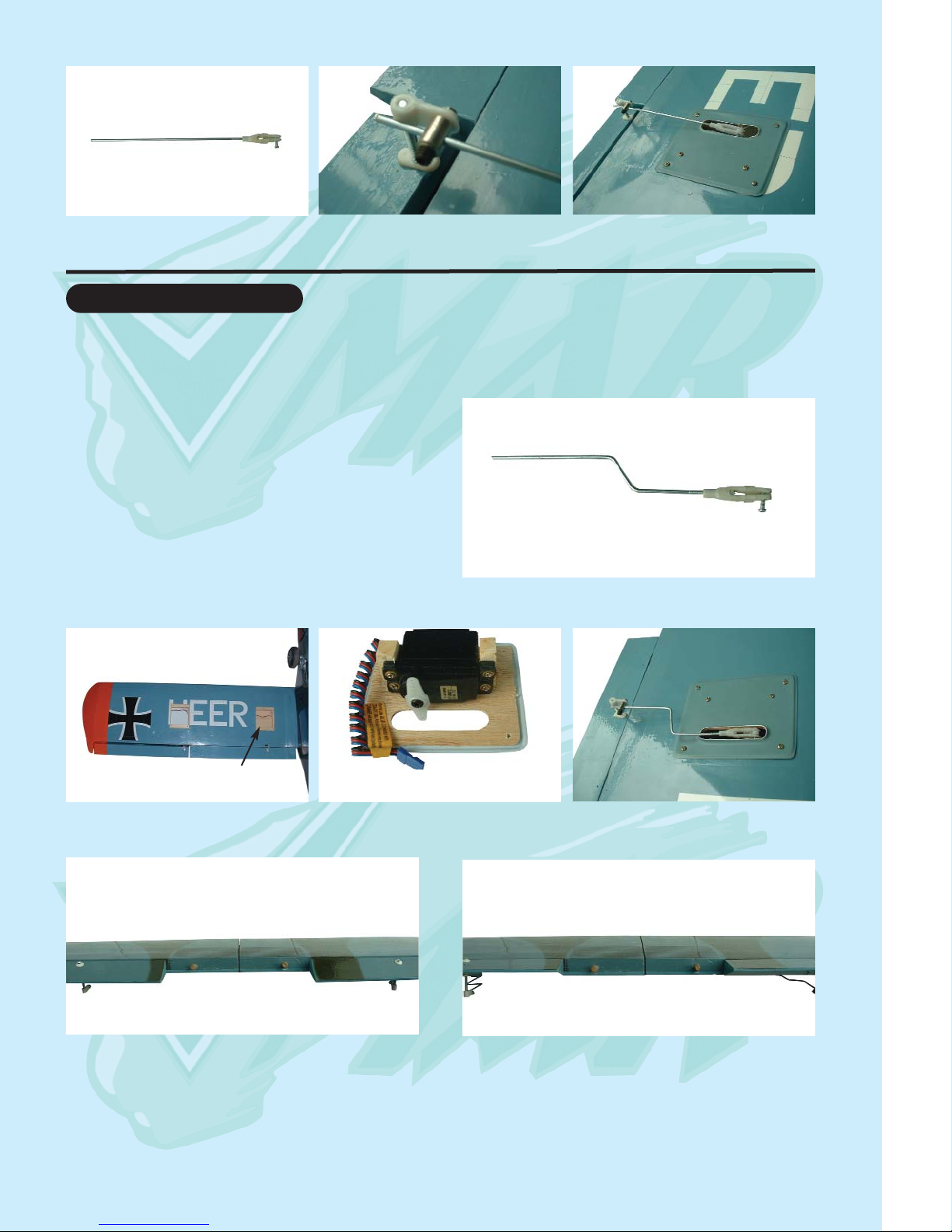
Install the aileron control horns and EZ Connectors.
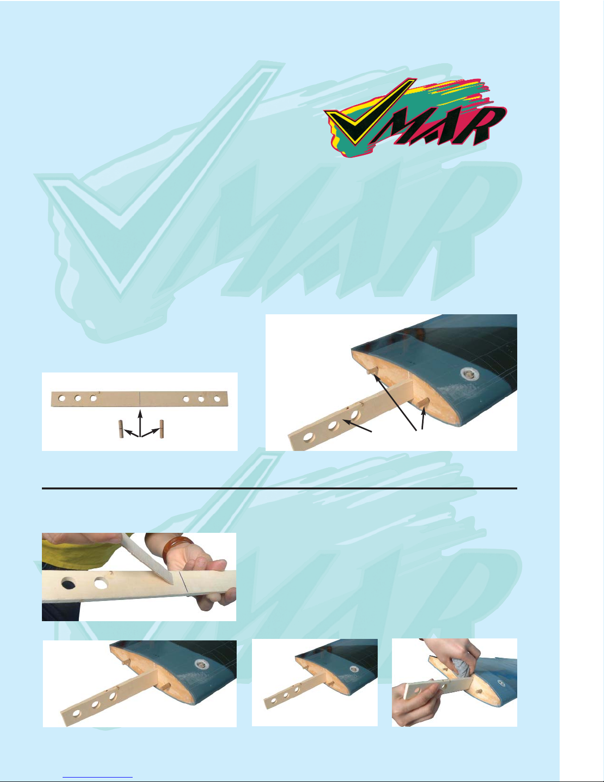
Aileron servo cavity
5. Aileron servo location
5.1 Aileron servo mount 5.2 Screw servo into position 5.3 Install horn & EZ Connector
Step 1 Consult your radio instruction manual and center each aileron servo by plugging it into the aileron chan-
nel of the receiver. Turn on the transmitter and then the receiver. Center the aileron trim lever on the transmitter.
Remove the servo arm mounting screw and the servo arm.
Step 2 Mount the servo arm back on the servo. Position the arm to be parallel with the back edge of the wing.
Screw the arm into place with the servo arm mounting screw supplied with the servo.
Locate the two aileron control rods in the hardware bag. Ensure the clevises are screwed well onto the threaded
portion of the rod. Rotate and tug aggressively on the clevises and ensure that they are not loose on the rods.
Tape the ailerons into their neutral position so that they are even with the trailing edge of the wing and not pointing
either up or down.
Step 3 Ensure that the aileron control horns are screwed onto the threaded aileron control horn bolts and that both
control horns are in approximately the same place on their respective bolts.
Step 4 Connect the aileron servo rods to the aileron control horns.The one end with the clevis will be attached to the
servo output arm.
Step 5 Connect the other end of the rod to the control horn pre-installed with an EZ connector
Step 6 Carefully peel back and remove the masking tape holding the ailerons.
Step 7 In the case of computer radios couple the servos together by connecting them to the appropiate receiver channel.
In the case of analog radios couple the servos together using a Y harness
Step 8 Turn on your radio and activate the ailerons using the aileron stick and ensure a smooth full motion can be
achieved.
Step 9 With the wing top side up and viewed from the back, ensure that moving the transmitter aileron stick to the
left raises the left aileron and lowers the right aileron. Movement of the stick to the left will roll the aircraft to the left.
(Counterclockwise roll of the wing when viewed from the back ).
Step 10 With the wing top side up and viewed from the back, ensure that moving the transmitter aileron stick to the
right raises the right aileron and lowers the left aileron. Movement of the stick to the right will roll the aircraft to the
right.

Stage 7
5
6.1 Aileron control rod assembly 6.2 Aileron control horn assembly 6.3 Aileron control rod installed
FITTING FLAP SERVOS
To install the aileron servos into the wing you will need
the following items :
- 2 servos
- Servo mounting screws and grommets as supplied
with the servo.
- Servo control arm as supplied with the servo.
- Two flap control rod assemblies
- Low tack masking tape.
7.1 Flap control rod assembly
7.2 Flap servo location 7.3 Flap servo installed in position 7.4 Final flap instalation
7.5 Flap down 7.6 Flap up
Flap servo location

Stage 8
Stage 9
Stage 10
6
FITTING THE HORZONTAL AND VER-
TICAL STABILIZERS
To mount the stabilizers to the fuselage you will need.
- Fuselage
- Vertical stabilizer with pre-installed rudder
- Horizontal stabilizer with pre-installed elevator
The completed fuselage slotsshould look like this
Vertical slot
Horizontal slot
Horizontal stabilizer with pre-installed elevator
Vertical stabilizer with pre-installed rudder
Check the fit of the horizontal stabilizer
in its slot. Make sure the tail is square
and centred to the fuselage by taking
measurements as shown in the dia-
grams on the right, but don’t glue any-
thing yet.
Equal
distance
Equal distance
900
9.1 Trial fit the horizontal stabilizer in
its slot
With the horizontal stabilizer cor-
rectly aligned, mark the shape of the
fuselage on the top and bottom of
the tailplane using a water sol-
uble non-permanent felt-tip pen as
shown here.
10.1 Mark the top of the horizon-
tal stabilizer
10.2 Followed by the bottom

Stage 11
Stage 12
Stage 13
7
Now remove the horizontal stabiliz-
er. Using a sharp knife and a ruler
CAREFULLY cut 2mm inside the
marked lines and remove the cover-
ing on the top and bottom of the tail
as shown. Make sure you only cut
the film and not the wood, otherwise
the horizontal stabilizer will be
severely weakened.
11.1 Marked lines on horizontal
stab
11.2 Cutting inside the lines.
11.3 Remove covering from top
surface
11.4 Exactly the same underneath 11.5 Clean off any traces of pen
Now apply sufficient epoxy to the top and bottom of the
horizontal stabilizer. Use 30 minute epoxy to ensure a
strong bond and give yourself plenty of working time.
Insert the horizontal stabilizer in its slot in the fuselage
and re-check the alignment as in Stage 9. Excess epoxy
should be cleaned off with a rag or tissue before it cures.
12.1 Apply plenty of epoxy 12.2 Slide the horizontal stabilizer
into place
12.3 Wipe off excess epoxy
Check the fit of the vertical stabilizer in its slot.
Make sure that it is glued square to the horizon-
tal stabilizer and fuselage
FITTING THE VERTICAL STABILIZER WITH RUDDER
13.1 Trial fit the vertical stabilizer into fuselage.

Stage 14
Stage 15
Stage 16
8
14.1 Mark both sides of the verti-
cal stabilizer
14.2 Carefully cut through the
covering. Do NOT cut the wood.
14.3 Remove covering from both
sides
Mark the shape of the fuselage on the left and right
sides of the vertical stabilizer using a felt-tip pen. Now
remove the vertical stabilizer, using a sharp knife &
ruler, CAREFULLY cut just 2mm inside the marked
lines and remove the covering on both sides of the fin,
just as you did with the horizontal stabilizer, making
sure you only press hard enough to cut the covering,
not the wood of the vertical stabilizer.
Now apply sufficient epoxy to both sides and the bottom
of the vertical stabilizer. Use 30 minute epoxy to ensure
a strong bond and give yourself plenty of working time.
Insert the vertical stabilizer in its slot in the fuselage
and re-check the alignment. Excess adhesive should
be cleaned off with a rag or tissue before it cures.
15.1 Apply plenty of epoxy 15.2 Slide the vertical stabilizer into place
FITTING THE MAIN LANDING GEAR
Identify the main landing gear components shown
below here.
- 2 main landing gear assemblies
- 2 main wheels ( 60mm x 20mm)
- 1 ABS main landing gear cover (with 6 mounting
screws)
- 4 sheet metal screws 5 x 35 mm & 2 straps
- 2 wheel collars
16.1 Main landing gear components

Stage 17
Stage 18
9
16.2 Turn over the fuselage &
locate the pre-drilled main land-
ing gear mounting holes
16.3 Use 4 sheet metal screws and
2 straps to mount the main landing
gear onto the fuselage
16.4 Drill pilot holes with a
1/16 (or 1,6 mm) drill-bit
16.5 Mount the main landing gear
fairing with a 2x10 screw
16.6 Install the wheel 16.7 Install the main landing gear
cover using 6 screws.
FITTING THE TAIL WHEEL
17.1 Insert the tail wheel steering
wire into the steering guide tube
17.2 Screw the tail wheel assem-
bly to the fuselage
17.3 Trim off the excess tail steer-
ing wire
Install the tail wheel assembly. Note that the tail wheel
assembly has a loose wire end. Slide the loose wire
end into the sleeve tube that has been installed into
bottom of the rudder. Position the plastic bracket on
the bottom of the fuselage. Mark the location of the
screw holes. Tap the holes with the screws and then
fasten the plastic bracket to the fuselage. See the
illustration below.
FITTING THE FUEL TANK
To assemble the fuel tank you will need the following
items:
- The fuel tank and fuel stopper assembly (supplied)
- The clunk (supplied)
- About 7” (20 cm) of medium ID silicone fuel line (DUB
197 or similar)
- Cross head Philips screw driver

Stage 19
10
18.1 Use 100 mm (4 in) for fuel line
and 50 mm (2 in) for pressure line
18.2 Illustration of fuel line posi-
tioning inside the tank
18.3 Fuel tank installed on the
power module. Use silicone.
100 mm (4 in) for fuel line
50 mm (2 in) for pressure line
fuel line
pressure line fuel line
pressure line
INSTALLING THE ENGINE
The engine and the fuel tank are installed onto the
power module. First remove the power module from
the fuselage by removing the 4 nuts & washers
19.1 Aluminum engine mount 19.2 Power module assembly 19.3 Engine thrust line
Fuel tank
holder dowel Engine thrust line
19.4 Engine and engine mount
recommended orientation.
19.5 Engine and fuel tank posi-
tioned on the power module
19.6 Throttle control connection
to the engine
fuel line
pressure line fuel line
pressure line
19.7 Cowl installation 19.7 Install the muffer and con-
nect the fuel and pressure line
19.8 Install asuitable prop and
spinner
VMAX Pro.46 engine recommended

Stage 20
Stage 21
Stage 22
11
FITTING ELEVATOR AND RUDDER CONTROL HORN
The elevator horns are to be fitted on the underside of both right & left
of the elevator halves. Pierce the covering over the pre-drilled hole
for the control horn installation as shown.
20.2 Elevator control horn location 20.3 Rudder control
horn location
20.4 Elevator and rudder control
horn connected to the control rod
20.1 Control horn assembly
Elevator control horn location
INSTALLING THE SERVOS
Install the rubber servo grommets and brass ferrules supplied with your radio
equipment. The three servos that control the elevator, rudder and throttle are
Installed in the servo tray mounted in the fuselage. Remove the servo tray from
the fuselage, mounting the servos to the servo tray as shown. 21.1 Universal servo mount
21.2 Note the orientation and positions of the
three servos in their tray
Throttle servo
Elevator servo
Rudder servo
21.3 Throttle, elevator and rudder servos connect-
ed to their respective push rods
22.1 Consult the picture showing how the throttle, rudder
and elevator servos are positioned and connected to the
pushrods.
CONNECTING THE PUSHRODS TO THE THROTTLE, RUDDER AND ELEVATOR SERVOS

Stage 23
Stage 24
Stage 25
12
Connect the elevator servo to the receiver and turn on your transmitter. Confirm that the
neutral positions of the elevator servo are sustained as per illustration 22.4
22.2 Pre-installed elevator and
rudder pushrod
22.3 Connect a clevis to the
servo arm
22.4 Connect the elevator
pushrod to the elevator servo arm
CONNECTING THE PUSHRODS TO THE ELEVATOR
23.1 Two independent elevator
control horns shown in position
23.2 Connect the elevator
pushrods to the control horns
23.3 Loosen collars to align elevator
surfaces. Re-tighten collars
securely
CONNECTING THE PUSHROD TO THE RUDDER
Connect the rudder servo to the
receiver and turn on your transmit-
ter. Confirm that the neutral posi-
tions of the rudder servo are sus-
tained as per illustration 22.4
24.2 Connecting the rudder pushrod to the rudder control
horn
CONNECTING THE THROTTLE CONTROL
Connect the clevis to the engine throttle arm at roughly half throttle. Look
into the throat of the engine carburettor as you rotate the throttle arm and
select a position where the throttle opening is about half what it is when
fully open.
25.1 Throttle control rod
Connected to the engine throttle arm
engine throttle arm
25.2 Throttle control rod con-
nected to the engine throttle arm

Stage 26
Stage 27
13
Adjust the deflection of the control surfaces to match the specifications on page 15
You can reduce the amount of throw by doing either or both of the following:
- From the servo end, move the clevis or EZ connector to a hole in the servo arm that is closer to the servo output
shaft.
- From the control horn end, move the horn out further on the threaded bolts. Always confirm that the horn is still
thoroughly engaged with the threaded bolt after you have adjusted it.
ADJUST CONTROL SURFACE THROW LIMITS.
FINAL R/C SET-UP
Before starting the final
set-up of the model,
switch on the radio and
ensure that all trims are
in their neutral posi-
tions. Check that the
ailerons, elevator and
rudder are centred. If
any adjustments are
needed, do these by
uncoupling the relevant
clevis and turning it
clockwise to shorten
the linkage or counter -
clockwise to lengthen it.
Only when each control
surface has been cen-
tred mechanically in
this way should you
begin adjusting the sur-
face movement (or
throw)
Now confirm
that the con-
trol surfaces
are moving
in the correct
direction.
Use the
servo revers-
ing swiches
on your
transmitter to
reverse the
direction of a
servo if nec-
essary. The
most popular
transmitter
mode (with
the throttle
on the left,
with ailerons
and elevator
on the right)
is shown
here.
Stage 28
ELEVATOR
UP
ELEVATOR
DOWN
AILERON
UP
AILERON
DOWN
AILERON
DOWN
AILERON
UP
RUDDER
RIGHT
RUDDER
LEFT

29.1 Consult your radio manual for instructions
about hooking up your receiver battery, receiver and switch harness.
29.2 Wrap the battery pack securely in foam suitable for RC equipment and wrap the foam insulated pack in a plas-
tic bag or cling wrap.
29.3 Thread the battery pack connector back through from beneath the fuel tank to the radio compartment by pass-
ing the battery connector through an opening beside or beneath the fuel tank.
29.4 Connect the battery connector to your radio system according to the radio manual.
30.1 Consult your radio manual for instructions about hooking up your receiver.
30.2 Plan where you are going to put the receiver with consideration for routing the antenna safely.
30.3 Wrap the receiver securely in foam suitable for RC equipment and wrap the foam insulated receiver in a plas-
tic bag or cling wrap.
30.4 Generally in the absence of specific instructions from the radio manufacturer, it is recommended that the
receiver should be placed where it is least likely to have impact during a crash. Keep the battery pack and other
heavy loose items ahead of the receiver.
31.1 Consult your radio manual for instructions about testing and operating your radio system.
31.2 Pay particular attention to charging your radio system batteries and range testing the system before and after
each flight.
31.3 Check that all controls are working correctly before and after each flight.
The CG for your DO 27 is located at 75 to 80 mm (3 to 3-1/4 inches) back from the leading edge of the wing when
the wing has been attached to the fuselage.
For the initial flight, the CG should be located at 75mm (3 inches) back from the leading edge of the wing when
the wing has been attached to the fuselage.
The CG is measured with the engine, radio gear and all other components installed but WITH NO FUEL IN THE
TANK.
Set up the CG as it will be when you fly it BUT WITH NO FUEL IN THE TANK.
It is very important to have the CG correct. Flying your model with the CG too far back will likely lead to loss of control
and a crash.
If you discover that after you have assembled your model and installed your radio and engine that the CG is incor-
rect you must bring the CG to the correct location by doing the following BEFORE FLYING :
- Move the battery pack fore or aft.
- Move other components fore or aft.
- Change engine to a lighter or heavier model.
- Add weight to the nose or tail. If adding it to the nose, try to make it useful by going to a heavier duty engine
or adding a spinner with a heavy metal backing plate. As a last resort, add stick on “dead” weight where appro-
priate.
14
INSTALLING THE RECEIVER BATTERY
Stage 29
Stage 30 INSTALLING THE RECEIVER
Stage 31 COMFIRM RADIO OPERATION
Stage 32 BALANCING THE AIRCRAFT.

NOTE : The throws are measured at the widest part of the elevator, rudder and aileron. Adjust the position of the
pushrods at the control/servo horns to control the amount of throw. You may also use the ATV’s if your transmitter
has them but the mechanical linkages should still be set so that the ATV’s are near 100% for best servo resolution.
High rate Low rate
ELEVATOR 1/2 “ ( 12mm) up 1/3” (7mm) up
1/2 “ ( 12mm) down 1/3” (7mm) down
RUDDER 1 “ (25mm) right 5/8” (13mm) right
1” (25mm) left 5/8” (13mm) left
AILERON 3/8” (11mm) up 1/4” (8mm) up
3/8” (11mm) down 1/4” (8mm) down.
Note: If your radio does not have dual rates, then set the control surfaces to move atthe low rate throws.
15
33.1 Once you have confirmed that the CG is
correct, you should do a thorough review of the
entire model before your first flight. Check every-
thing twice! Every hook up, every coupling, every-
thing! Do it twice!!
33.2 Before your first flight, have an experienced
flyer review your work. Do not fly your model until
it has been checked out by a third party who
knows how to fly and how to set up a model air-
craft.
33.3 Once you have completed your first flight,
get in the habit of checking your model over
before and after each flight! Don’t fly if you find
something that is not right!
Stage 33 CONFIRM MECHANICAL INTEGRITY
75 - 80 mm
3 - 3 1/4”
Elevator Aileron Rudder
5/8”
13mm
5/8”
13mm
1/4”
8mm
1/4”
8mm
1/3”
7mm
1/3”
7mm
CG
Parts for this VMAR Model
In the event that you require replacement parts for you VMAR VAN RV - 4, you can order parts from your retailer or from the
VMAR On - line store at www.richmondrc.com. Please see the IMPORTANT INFORMATION sheet for parts for this model.
Fuselage #VA.104H.0461F (with servo tray & all rods)
Wing set #VA.104H.0461W (a set of left and right with joiner ect)
Tail set #VA.104H.0461T (contains horizontal and vertical stabilizers)
Cowl #VA.104H.0461L (fiberglass)
Canopy set #VA.104H.0461N (canopy and frame)
Main gear #VA.104H.0461MG (fiberglass main landing gear with axle set)
Wheel pant set #VA.104H.0461WH (with main gear fairing set)
Covering set #VA.104H.0461V (POLYCOTE ECS)
Wing parts bag #VA.104H.0461WP (spar joiner, aileron rods ect)
Master bag #VA.104H.0461MB (as in kit)
For aftermarket parts and other information related to this model see VMAR On - line at
www.richmondrc.com.

16
Your VMAR DORNIER DO 27 Model is covered in POLYCOTE ECS.
The new ULTRA TOUGH POLYESTER covering from VMAR !
WHAT’S IT
ALL ABOUT ?
POLYCOTE ECS is an Enhanced Covering System Engineered in
Canada and Available only from VMAR. With POLYCOTE ECS the
graphics are inside the covering... not stuck on top. No Decals! No
Layers! No Strips! No Stripes! VMAR Models using POLYCOTE
ECS have very few seams and our proprietary SURE SEAL system
ensures that the seams stay down! Best of all, POLYCOTE itself is
a totally fuel proof ULTRA TOUGH POLYESTER
For more information, Please visit our website:
www.richmondrc.com/support.htm
DORNIER DO 27
TM
TM

Richmond RC Support Services
SUPPORT INFORMATION
Support Related to VMAR ARF Products
©Richmond RC Supply Ltd. All Rights Reserved. Unauthorized commercial use strictly prohibited.
Prices, Specifications, Features and Availability subject to change without notice
Production Colors and Graphic Schemas may differ from that shown.
Artwork, text and information for the use of consumers and Richmond RC customers only
2002-10-06 21:00:46
http://www.richmondrc.com/support.htm [2/22/03 7:55:57 PM]
Table of contents