INTRODUCTION
Rickard’s VAV diffusers are designed to modulate the volume of
warm or cold air to meet the zones demand. In some cases, typically
in particularly cold zones, the warm supply air is insufficient to heat
the zone adequately. To satisfy this shortfall, Rickard has developed a
range of in-line top-up duct heaters.
FORM FACTOR
These heaters have been designed to be fitted to the take-off of the
main duct, upstream of the diffuser. By positioning the heater be-
tween the main duct and the diffuser flex, the heater is able to meet
the building codes that are required for some markets.
Any Rickard MLM diffuser supplied with a round duct can be fitted
with an in-line duct heater and controlled. This applies to ceiling
diffuser types VCD1, VSD1, CCD3, CSD3, VSW1 and CSW3’s. A 2m
ribbon cable is supplied to connect the in-line heaters triac to the
diffusers main controls.
If used correctly, electric duct heating in VAV diffusers can be consid-
ered an energy saving device. By using them in offices that are typi-
cally colder than the building average allows the central plant to
produce less heating in winter than is otherwise possible.
The most efficient scenario in heating is for the central plant to sup-
ply sufficient heated air to allow most of the zones to be in control
when the diffusers damper is close to minimum position. Zones that
are colder are controlled by the diffuser opening further. Zones that
cannot be satisfied by the diffuser supplying warm air at full volume
are toped up with supplementary heating.
The most efficient scenario in cooling is for the central plant to sup-
ply sufficient cool air to allow most of the zones to be in control
when the diffuser dampers are close to minimum position. Zones
that are warmer can be controlled by the diffuser opening further.
Zones that cannot be warmed sufficiently by reducing the cold air
supply can be controlled by heating this reduced volume of air.
If the room temperature were to fall by 0.5°C below set point, the
Triac Controller will commence energizing the heater proportionally
and will fully energize the heater when the room temperature is ap-
proximately 1.5°C below set point.
Integration of the Rickard VAV diffuser system with the central plant
BMS is possible by using our MLM Interoperable BMS Compatible
Controls.
PROPORTIONAL HEATING
For accurate control of room temperature, the electric re-heater is
controlled on a step-less, proportional basis. In addition to having a
proportional output signal for cooling control, the temperature con-
troller also has a proportional output signal for heating.
This is done by means of a triac switching set (current valve) which
varies the heater output capacity by cycling the power supply to the
heater on and off –Pulse Width Modulation (PWM). This switching
takes place over a cycle of approximately 2 seconds and always oc-
curs at zero voltage to avoid radio frequency interference and volt-
age spikes. The “on” and “off” periods are varied in proportion to
the amount of heating required, i.e. a required heating capacity of
75% will result in an “on” period of 1.5 seconds and an “off” period
of 0.5 seconds.
CONTROLS
In a situation where multiple diffusers are controlled from a single
controller, each diffuser will be fitted with its own triac that will re-
ceive a heating signal from the Master controller. The heating signal
transmitted by the controller is a 9 Volt DC signal.
From the table “Maximum Recommended Heater Output (Watts)”, it
will be noted that for each neck total pressure there is a specific
heater output quoted and for each diffuser size a standard heater
capacity is referenced. For example, in the case of a VCD 250 diffus-
er, the re-heater sleeve would be factory fitted with a 1500 watt
heater, which by utilizing the RICKARD MLM or MLM Interoperable
BMS Compatible Controls, can be electronically set for any output
from as little as 100 watts to 1500 watts to match the design engi-
neer’s requirements for minimum cooling mode supply air flow and
desired leaving air temperature. Therefore, if the diffuser neck total
pressure were to be set at 50Pa and the minimum desired air flow
was 30% of maximum with 15°C air temperature rise, the heater
output for a VCD 250 should be set to 1300 watts. Kindly refer to the
help section in the MLM software program for more detailed infor-
mation.
IMPORTANT ELECTRICAL INFORMATION: Electrical reticulation
should be designed to have the capacity to manage the heaters full
capacity e.g. when a heater is set to 50%, the heater element draws
the same current as it would when set to 100% but it is drawn for
50% of the time.
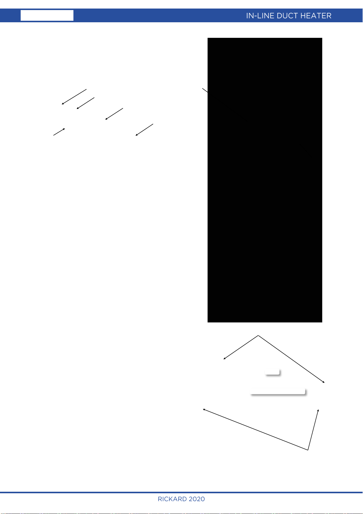
Bypass Damper
Face Damper
In-line Heater
Diffuser
AHU
Return Air
SAMPLE DUCT LAYOUT