Rickard MLM 24 User manual

RICKARD 2015 ELECTRONIC VAV CEILING DIFFUSER (VCD, VRD,VSD1)
EASY INSTALLATION WITH NO CABLES
FLEXIBILITY TO FIND THE PERFECT SENSOR
LOCATION
INDIVIDUAL ROOM TEMPERATURE CONTROL
ACCURATE ROOM TEMPERATURE SENSIING
QUICK & EASY COMMISSIONING
NEW MODERN SLIM DESIGN
NO TRUNKING OR DRAW BOX
MLM WIRELESS WALL
THERMOSTAT

MLM WIRELESS WALL THERMOSTAT
RICKARD 2018
FEATURES
The Rickard MLM Wireless Wall Thermostat or RF Wall Thermostat
has been designed to give the user individual temperature control
and accurate room temperature sensing without compromising floor-
plan flexibility. Since it is wireless the cost of installation is reduced
considerably. VAV diffusers with onboard sensing have always had
the advantage of flexibility as the built in sensor and the outlet can
be moved together when a floorplan design is changed. Although
considerable effort has been made to sense accurately with onboard
sensing, inadequate pressure and large temperature differences be-
tween supply air and room air especially in heating can result in
sensing inaccuracies.
Now that the Rickard Wireless Wall Thermostat is available, accurate
sensing and diffuser flexibility is possible without the cost and incon-
venience of moving a wired Wall Thermostat. Wireless wall thermo-
stats are also considerably cheaper to install since they don’t need
draw boxes fitted for their mounting, trunking fitted for cabling and
the hassle of pulling and routing wall thermostat cables to the diffus-
er.
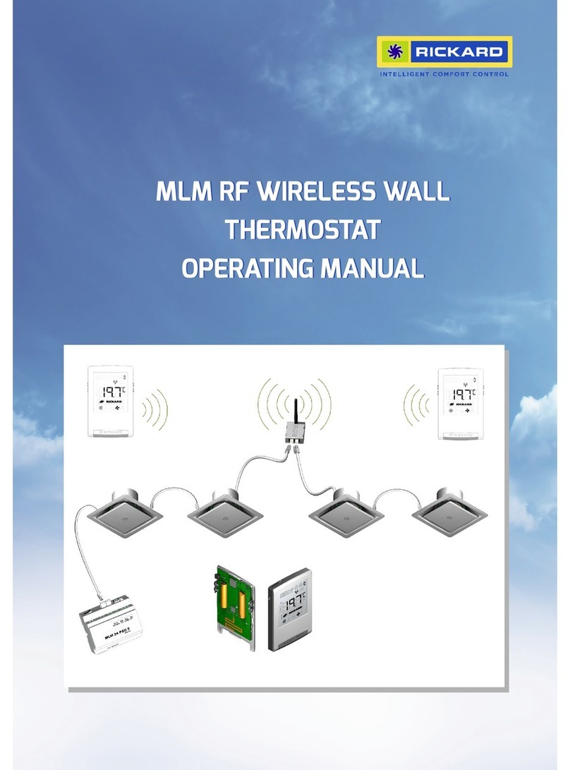
Every installation requires an Access Point (AP) per Power Supply Unit
(PSU). Each AP can communicate with up to 15 wireless wall thermo-
stats. Commissioning is made simple with Rickard’s free MLM soft-
ware and an intuitive thermostat/diffuser pairing procedure. A simple
guide is available to get you started.
HARDWARE
The MLM RF Wall Thermostat consists of the following hardware
units: an Access Point and the RF Wall Thermostat. These hardware
units in combination with the MLM Tool rev 8.xx application software
form the MLM RF system.
The Access point is powered by the MLM bus and the RF Wallstats
are each powered by a pair of Lithium AAA batteries, with a typical
operational life of 3-5 years. To conserve power, the RF communica-
tion is adaptive and could vary between 1 and 10 minutes, depend-
ing on the operational requirements of the control system. During
commissioning however, this period is reduced to a few seconds.
The following MLM RF hardware models are available:
MLM 24 RF Access Point (2m connecting cable included)
MLM 24 RF Wallstat
MLM 24 RF Pod Sensor
HARDWARE INSTALLATION
The Rickard MLM RF Wall Thermostat is simple and easy to install.
Since no cable is used, no draw box is required and can be fitted to
any wall surface in any position. The diagonal slots allow horizontal
and vertical alignment with 2 screws. There are four additional round
holes if required.
The RF system requires an AP (Access Point) to be installed within a
50 meter radius of the RF Wallstat. One AP can be installed per Pow-
er Pack Unit at any point on the MLM24 slave cabling link. Ensure
the AP is installed centrally among the RF wallstats, normally inside a
ceiling void. Ensure the antennae wire protruding from the AP enclo-
sure is fixed in a vertical position. Install the AP at least one meter
away from any sheet metal objects. Ensure the AP is securely at-
tached to a solid object.
A maximum of 15 Wallstats can be installed per AP. Please follow the
installation instruction provided with the RF Wallstat to fit the back
shell to a wall. Fit the two batteries provided orientated according to
the polarity indicated on the board. NOTE: 1.5V AAA lithium cells
should always be used. Lithium cells are readily available off the
shelf. If standard AAA’s are used, the RF wallstat will stop functioning
long before the batteries are depleted. Lithium cells maintain their
Voltage until completely depleted and therefore last considerably
longer. The RF wallstat will not operate when the voltage drops.
After installing the batteries, clip the remote unit onto the back shell.
The remote unit will be in sleep mode and the LCD screen will be
switched off.
Note: Do not mix wired and wireless wall thermostats on the same
Power Supply Unit (PSU).
Note: One onboard controller and change-over sensor (supply air
sensor) is required per zone on sites that switch between heating
and cooling. This allows the diffuser to reverse direction when the
supply air temperature changes between heating and cooling. Please
ensure the diffusers are correctly commissioned. The onboard con-
trollers sensing and setpoint should be disabled, the change over
sensor enabled and sensing and setpoint should be enabled on the
RF Wall thermostat. These settings can be adjusted through the MLM
Application.

MLM WIRELESS WALL THERMOSTAT
RICKARD 2018
Menu
Enter
Sensing Port
Temp. Down
Temp. Up
COMMISSIONING
Commissioning is a simple two stage process. First, link the remote
RF Wallstats to the correct Access Point. This is achieved by activat-
ing the Access Point linking mode on the MLM application and the
wallstat pairing mode on the device. Once the linking is complete,
the wallstats need to be zoned to the appropriate diffuser. The zon-
ing follows a simple procedure using the MLM application. Please
see the MLM RF User Manual for full commissioning Instructions.
RF NETWORK STATUS AND HEALTH
The MLM Application has the functionality to monitor the RF Net-
works status and health.
The Battery and Signal Strength health of the RF network can be
determined using the built in MLM RF Network Status Wizard.
If required, a Wireless Wallstat can be removed from the system by
using the built in wizard or by manually selecting the end point dis-
played on the application.
Communication errors are also displayed on the Wallstat icon if they
occur i.e. when a WS is non-responsive the WS icon in the network
view will be displayed in yellow.
Rezoning wallstats is a simple matter of re-assigning them with the
MLM application.
SETPOINT ADJUSTMENT
The wallstats setpoint can be adjusted as follows:
1. When in temperature or setpoint display, press the up or
down arrows on the right side of the wallstat to increase or
decrease the setpoint one degree at a time. The value can be
accepted by pressing the enter button (bottom left). Alterna-
tively it will be accepted automatically after a short delay.
Using the menu button (top left), select setpoint adjustment mode
(SP). Follow procedure (1) above to adjust.
AESTHETICS
DISPLAY BUTTONS
The Rickard Wall Thermostat has been designed with discreet but-
tons located on either side of its body. One side allows straight for-
ward temperature adjustment and the other advanced user control.
Right Hand Side Buttons
The buttons located on the right hand side adjust a value up or
down.
Left Hand Side Buttons
The buttons located on the side left hand side give the user access
to advanced commissioning functions. The Menu button is located
above the Enter Button. Standard symbols depict Menu and Enter on
the side of the casing. Each press of the Menu button cycles through
each option and the enter button writes the value to memory.
DISPLAY OPTIONS
FUNCTIONAL EDITING OPTIONS
1. Set point Display: When activated Set point is displayed
instead of room temperature.
2. Temperature Display: By default the room temperature is
displayed.
3. RTC Display: Real Time Clock is displayed.
SENSING ACCURACY
The Rickard MLM Wall Thermostat has a built in sensing port de-
signed to accurately sample room temperature. It is important to find
a mounting location that best represents the occupants environment.
NOTE: Consider the effect of a hot or cold wall on the Wall Thermo-
stat’s sensing accuracy. External conditions can affect internal wall
temperatures to such a degree that the Wall Thermostat’s sensing
ability is also affected.
CONTROLS
1.
Compatible with MLM or MLC.
APPLICATION
The Rickard MLM RF Wall Thermostat;
LEFT‐HANDSIDE
RIGHT‐HANDSIDE

MLM WIRELESS WALL THERMOSTAT
RICKARD 2018
HARDWARE LAYOUT
Up to 50m RF Comms Radius Max: 15 Wall Stats/AP
One Access Point per PSU unit.
15 Diffusers Maximum/PSU
RF WALL THERMOSTAT
RF WALL THERMOSTAT
ACCESS POINT (AP)
POWER SUPPLY UNIT (PSU)
VAV DIFFUSER
RF WALL THERMOSTAT
Accurately senses and sets room temperature.
Converts any Slave diffuser into a Master so that it can con-
trol a zone of up to 15 diffusers.
Compatible with MLM and MLC systems.
SELECTION
Use when individual temperature control is a requirement.
Use when flexibility and sensing accuracy is a priority.
Use to reduce the cost of a Wall Thermostats Installation.
Use when stratification in heating is a problem.
SPECS
RF frequency 868MHz ISM band
Max TX level 10dbm
Receive level up to -100dbm
Encoding 2-GFSK
Communication rate 38 kBaud
Battery 2 x 1.5V AAA Lithium cell
Battery life 3 to 5 years.
Battery low voltage indication (< 2.8V)
RSSI RF signal strength indication (RSSI low at < -85 dbm)
Selectable setpoint/RTC/Room temperature display
Info display – Battery Voltage or RSSI display.
Other Rickard Thermostat manuals
Popular Thermostat manuals by other brands

Honeywell
Honeywell Chronotherm IV T8600D installation instructions

Venstar
Venstar VOYAGER T4900 owner's manual

Toupwell
Toupwell TP201 user guide

Aube Technologies
Aube Technologies TH111GFCI-P owner's manual

VDH
VDH ALFA D1-DP user manual

ardex
ardex FLEXBONE HEAT Non-Programmable Thermostat quick start guide