Ricoh FV-L500B1 User manual

1/31
FV-L500B1
User’s Guide Rev. 1.02
Small Cubic ype
5.0 Mega Pixel CCD
Monochrome PoCL Camera Link Camera
FV-L500B1
User’s Guide
RICOH COMPANY, LTD.

2/31
FV-L500B1
User’s Guide Rev. 1.02
Table of Contents
1
Connector Specifications.....................................................................................................................................
1.1
Camera Link Connector...................................................................................................................................... 3
1.2
Power-I/O Connector .......................................................................................................................................... 4
1.3
Equivalent Circuit for the Input Pin of the I/O Connector.................................................................................... 5
2
Camera Output Timing Charts.............................................................................................................................6
2.1
Normal Mode (Setting 10H: 1XX0XXXX)......................................................................................................... 6
2.1.1
Horizontal iming.........................................................................................................................................6
2.1.2
Vertical iming ............................................................................................................................................. 7
2.1.2.1
Normal Full Scanning (Setting 10H: 1XX00XXX, 11H: XXX0X000).................................................. 7
2.1.2.2
Partial Full Scanning (Setting 10H: 1XX01XXX, 11H: XXX0X000) ................................................... 7
2.1.2.3
1/2 Partial Scanning (Setting 10H: 1XX01XXX, 11H: XXX0X001)....................................................8
2.1.2.4
1/4 Partial Scanning (Setting 10H: 1XX01XXX, 11H: XXX0X010)....................................................8
2.1.2.5
Variable Partial Scanning (Setting 10H: 1XX01XXX, 11H: XXX0X111)..........................................9
2.2
Binning Mode (Setting 10H: 1XX1XXXX).................................................................................................... 10
2.2.1
Horizontal iming....................................................................................................................................... 10
2.2.2
Vertical iming ........................................................................................................................................... 11
2.2.2.1
Binning Full Scanning (Setting 10H: 1XX10XXX, 11H: XXX0X000) ............................................... 11
2.2.2.2
Binning Partial Full Scanning (Setting 10H: 1XX11XXX, 11H: XXX0X000) .................................... 11
2.2.2.3
Binning 1/2 Partial Scanning (Setting 10H: 1XX11XXX, 11H: XXX0X001) ..................................... 12
2.2.2.4
Binning 1/4 Partial Scanning (Setting 10H: 1XX11XXX, 11H: XXX0X010) ..................................... 12
2.3
Data Order on the Camera Link Output............................................................................................................13
2.4
2 aps ransferring Image (2XE-1Y).............................................................................................................. 14
2.5
Pixel ransferring Image...................................................................................................................................14
Camera Operational Mode ................................................................................................................................. 15
3.1
Normal Mode .................................................................................................................................................... 15
3.1.1
Frame Exposure ........................................................................................................................................ 15
3.1.2
Electric Shutter ..........................................................................................................................................15
3.2
Pulse Width rigger Mode ................................................................................................................................16
3.2.1
Pulse Width rigger Mode(V-Reset)..................................................................................................... 16
3.2.2
Pulse Width rigger Mode (Non-Reset) .................................................................................................... 17
3.2.3
Exposure iming........................................................................................................................................ 17
3.3
Edge Preset rigger Mode................................................................................................................................ 18
3.3.1
Edge Preset rigger Mode (V-Reset) ........................................................................................................18
3.3.2
Edge Preset rigger Mode (Non-Reset)....................................................................................................19
3.3.3
Exposure iming........................................................................................................................................ 19
3.4
H Reset Mode................................................................................................................................................... 20
4
Communication Protocol ................................................................................................................................... 21
4.1
Communication Method....................................................................................................................................21
4.2
Communication Settings...................................................................................................................................21
4.3
Communication Format .................................................................................................................................... 21
4.4
Camera Control Command...............................................................................................................................24
4.4.1
Camera Command List .............................................................................................................................24
4.4.2
Descriptions of the Camera Control Commands....................................................................................... 26
5
Revision History.................................................................................................................................................. 1

3/31
FV-L500B1
User’s Guide Rev. 1.02
1 Connector Specifications
1.1 Camera Link Connector
SDR (3M) or equivalent
This product is a PoCL type.
When a frame grabber is PoCL compliant, DO NOT SUPPLY POWER FROM THE I/O CONNECTOR.
When a frame grabber is NOT PoCL compliant, supply power from the I/O connector.
Pin Assignment
Pin No. Signal Name Pin No. Signal Name
1 +12V 14 GND
2 X0- 15 X0+
3 X1- 16 X1+
4 X2- 17 X2+
5 Xclk- 18 Xclk+
6 X3- 19 X3+
7 Ser C+ 20 Ser C-
8 Ser FG- 21 Ser FG+
9 CC1-( RG) 22 CC1+( RG)
10 CC2+ 23 CC2-
11 CC3- 24 CC3+
12 CC4+ 25 CC4-
13 GND 26 +12V
Power-I/O Connector
Camera Link Connector

4/31
FV-L500B1
User’s Guide Rev. 1.02
1.2 Power-I/O Connector
HR10A-7R-6PB(Hirose)or equivalent
his connector is for the power supply (12Vdc) and input /output signals.
Use HR10A-7P-6S (Hirose) or equivalent for the cable side.
Pin Assignment
Input/output signals can be assigned through the camera setting communication (see table 4).
rigger input signal can be assigned either on Camera Link connector (CC1) or on the No. 2 pin of the
power-I/O connector through the camera setting communication.
IO Signal Patterns
Note 1: Output trigger signal has a latency of 30CLK (Approximately 470 nseconds) from input trigger signal.
Note 2: o input trigger signal from the I/O connector, change the setting of 12H.5.
Note 3: EXPDUR becomes high during exposure.
Voltage
Pin No. Signal Name IN / OUT Low Voltage High Voltage
1 GND IN 0V
IN 0 to +0.99V +2.3 to +3.3V
2 I/O-1 IN/OU OU 0V +3.3V
3 I/O-2 OU OU 0V +3.3V
4 I/O-3 OU OU 0V +3.3V
5 I/O-4 OU OU 0V +3.3V
6 +12Vdc IN +12Vdc
Command No. HR10A-7R-6PB (Hirose)
No.2 Pin No. Pin No.4 Pin No.5 Pin
F0H[ ..0] I/O-1 (SP4) I/O-2 (SP ) I/O- (SP2) I/O-4 (SP1)
Option 0
(Initial Setting) 0H IN/ RG N/A N/A OU / RG
Option 1 1H For est Use Only
Option 2 2H OU /CC4 OU /CC3 OU /CC”2 OU /CC1
Option 3 3H OU /FVAL OU /XSG OU /XSUB OU /CC1
Option 4 4H
OU /FVAL OU /LVAL
OU /
Right Image Data
(MSB)
OU /
Left Image Data
(MSB)
Option 5 5H OU /XHD
(high-active)
OU /EXPDUR
(Exposure) OU / RG OU /CC1
Option 6 6H OU /VD N/A N/A OU /HD
Others 7H-FH For est Use Only
5/31
FV-L500B1
User’s Guide Rev. 1.02
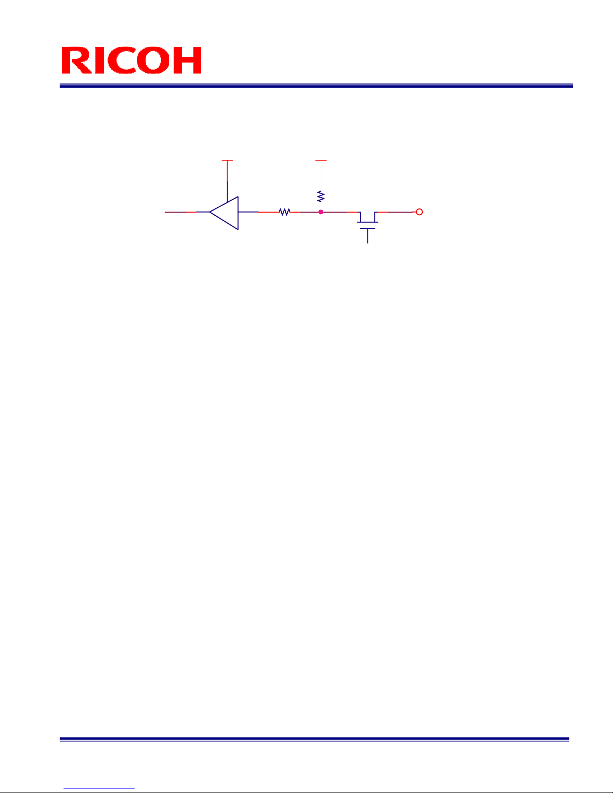
1.3 Equivalent Circuit for the Input Pin of the I/O Connector
+3.3V +3.3V
C7WH241FK
OSHIBA
RIGGER IN
10kohm
100ohm
On resister Max. = 30ohm
6/31
FV-L500B1
User’s Guide Rev. 1.02
2 Camera Output Timing Charts
2.1 Normal Mode (Setting 10H: 1XX0XXXX)
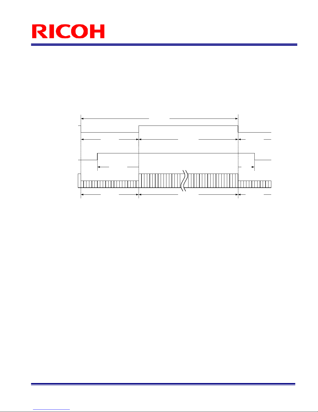
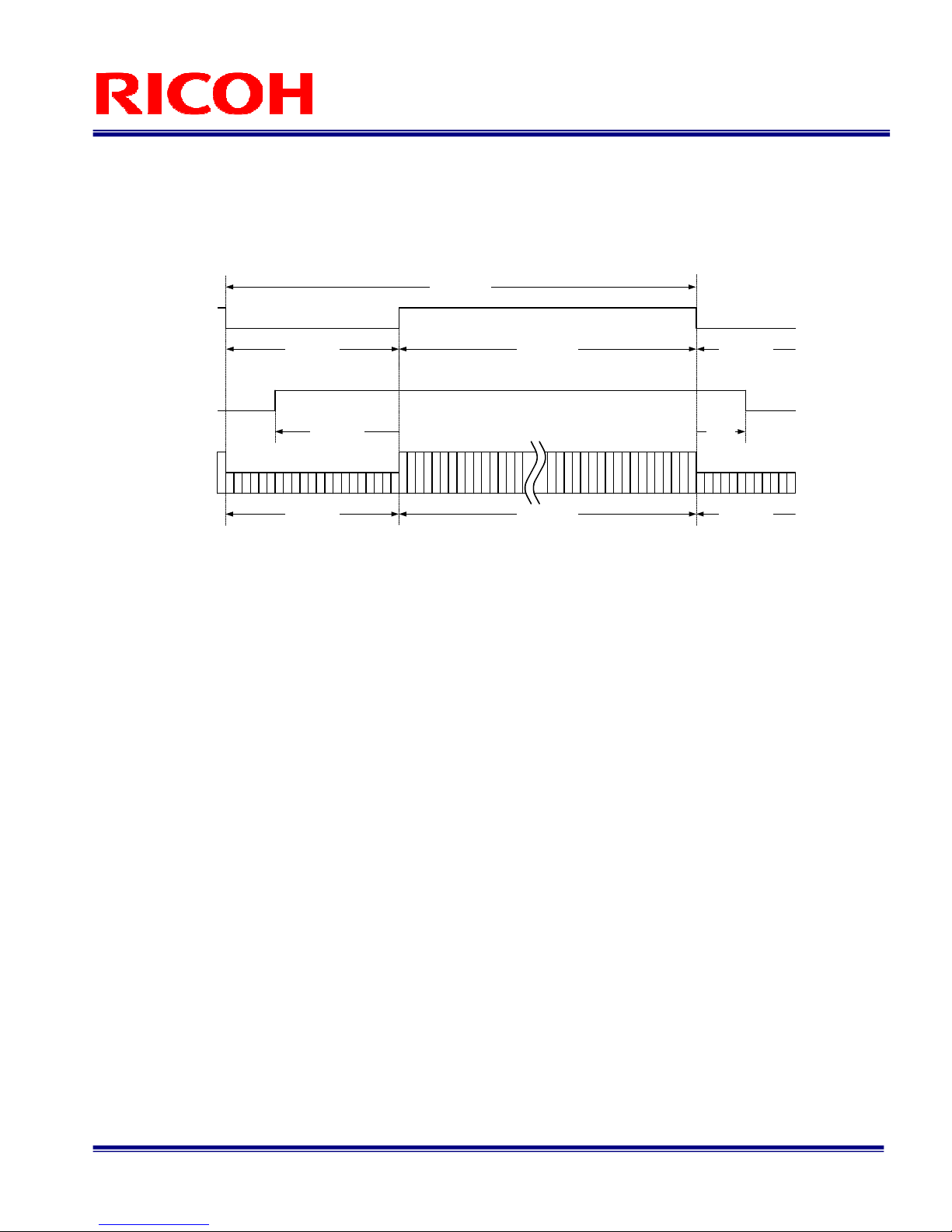
2.1.1 Horizontal iming
1 CLK = 15.625 ns
700 CLK1224 CLK
Video out
LVAL
DVAL
Horizontal blanking
1924 CLK One horizontal (1H)
1224 CLK700 CLK
700 CLK
Video output active term Horizontal
blanking
700 CLK
607 CLK 93
CLK
FVAL
7/31
FV-L500B1
User’s Guide Rev. 1.02
2.1.2 Vertical iming
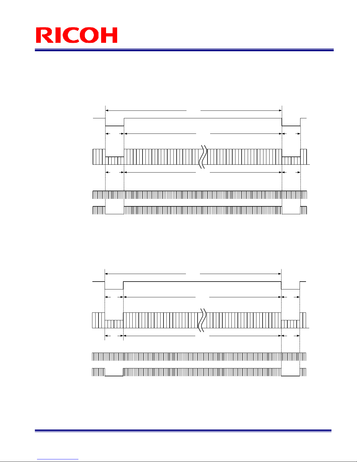
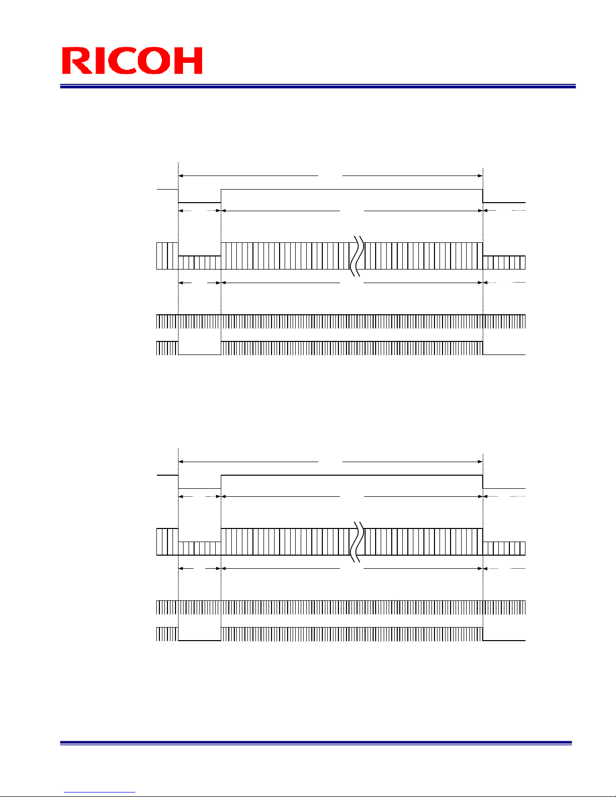
2.1.2.1 Normal Full Scanning (Setting 10H: 1XX00XXX, 11H: XXX0X000)
1 H = 30.063 μs, 16.000 Hz
2.1.2.2 Partial Full Scanning (Setting 10H: 1XX01XXX, 11H: XXX0X000)
1 H = 30.063 μs, 16.100 Hz
※ By transferring the blanking period pixels at a high rate, the frame rate of the partial full scanning can
be increased compared to that of the normal full scanning.
Video out
FVAL
2079H One vertical (1V)
2058H21H
2058H21H
Video output active term
1
2
2057
2058
21H
Vertical
blanking
Vertical
blanking
21H
LVAL
DVAL
Video out
FVAL
2066H One vertical (1V)
2058H8H
2058H8H
Video output active term
1
2
2057
2058
8H
Vertical
blanking
Vertical
blanking
8H
LVAL
DVAL

8/31
FV-L500B1
User’s Guide Rev. 1.02
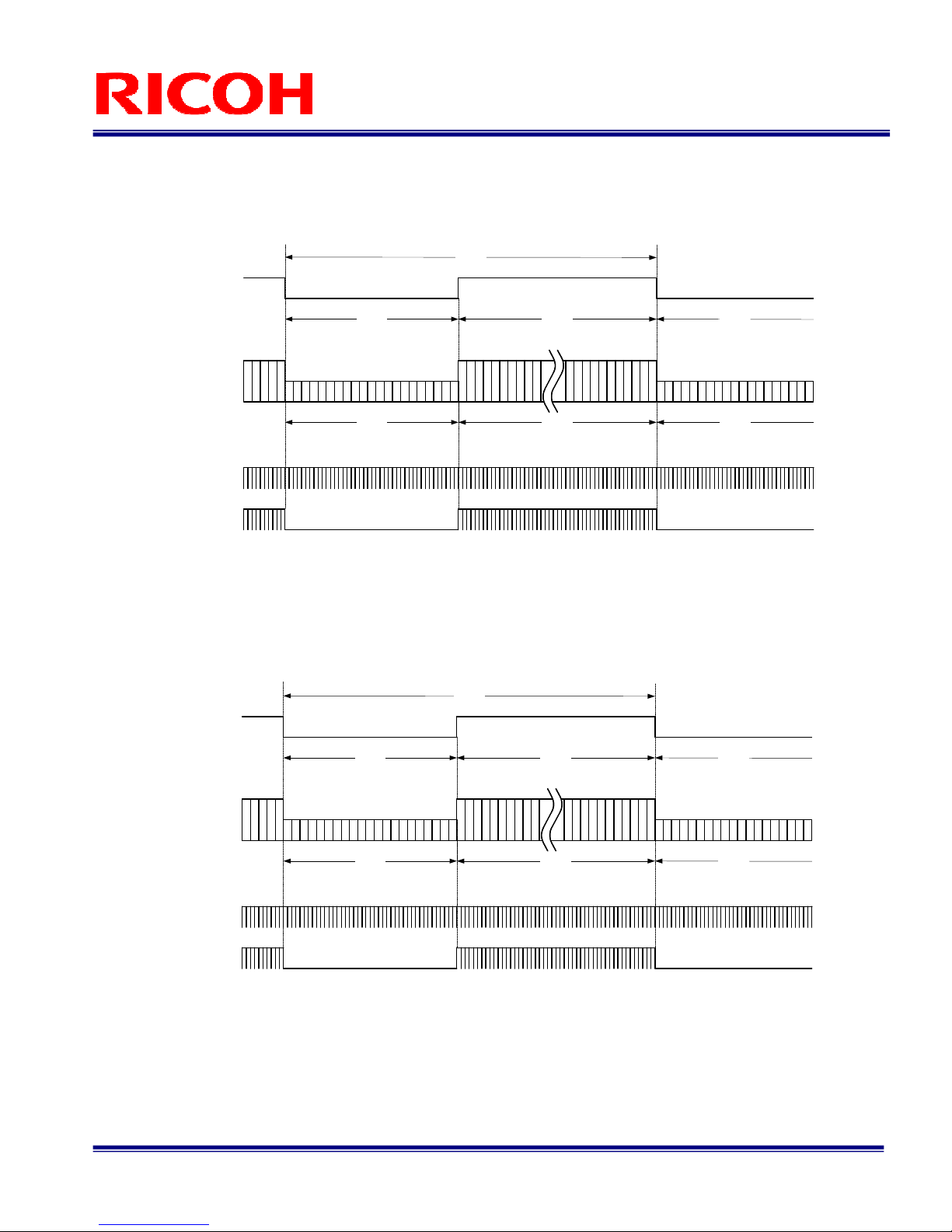
2.1.2.3 1/2 Partial Scanning (Setting 10H: 1XX01XXX, 11H: XXX0X001)
1 H = 30.063 μs, 32.015 Hz
2.1.2.4 1/4 Partial Scanning (Setting 10H: 1XX01XXX, 11H: XXX0X010)
1 H = 30.063 μs, 63.968 Hz
856H
Video out
Vertical blanking
1039H
One vertical (1V)
183H183H
Video output active term
1447
1448
593
594
FVAL
856H183H
Vertical blanking
183H
LVAL
DVAL
256H
Video out
Vertical blanking
520H
One vertical (1V)
256H
264H
264H
Video output active term
1143
1144
889
890
FVAL
264H
264H
Vertical blanking
LVAL
DVAL
9/31
FV-L500B1
User’s Guide Rev. 1.02
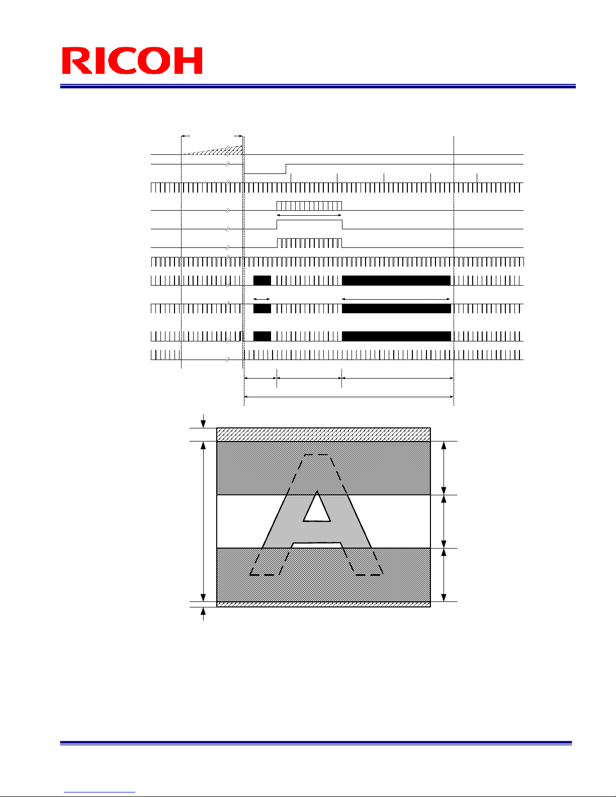
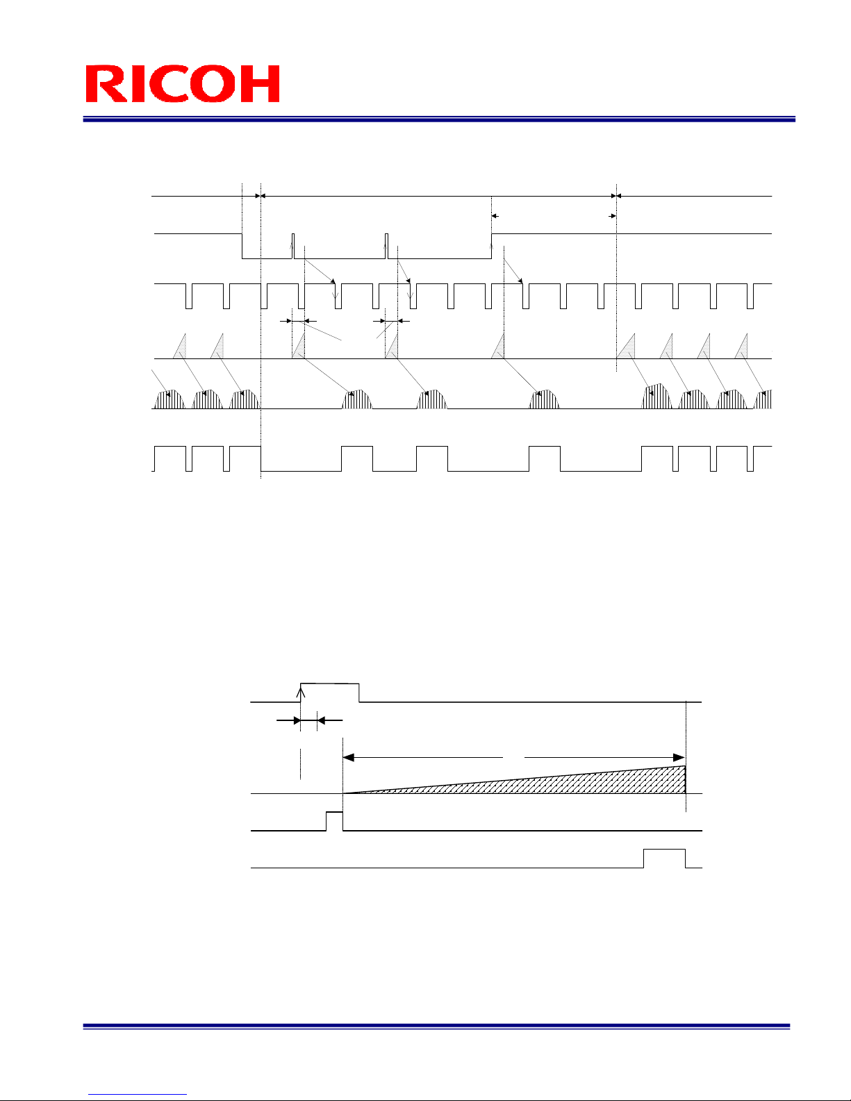
2.1.2.5 Variable Partial Scanning (Setting 10H: 1XX01XXX, 11H: XXX0X111)
Internal HD
Internal VD
Video out
EX _ RIG
FIX_ RIG (Common)
10 20 30 40 50
Exposure time
V1
V2
V3
SUB
FVAL
DVAL
LVAL
Number of the
effective lines [Y]
High speed
transfer [X+a]High speed transfer [f+g-X-Y]
Blanking (Front)
[BLK_F] Number of the effective lines [Y]
otal number of the line at 1 frame [ O AL_LINE]
Blanking (Back)
[BLK_B)
CCD effective
lines
Blanking
(Front)
Effective
lines
Optical black
+
Dummy bit
Blanking
(Back)
Optical black
10/31
FV-L500B1
User’s Guide Rev. 1.02
2.2 Binning Mode (Setting 10H: 1XX1XXXX)
2.2.1 Horizontal iming
1 CLK = 15.625 ns
700 CLK1224 CLK
Video out
LVAL
DVAL
Horizontal blanking
1924 CLK One horizontal (1H)
1224 CLK700 CLK
700 CLK
Video output active term Horizontal
blanking
700 CLK
607 CLK 93
CLK
FVAL
11/31
FV-L500B1
User’s Guide Rev. 1.02
2.2.2 Vertical iming
2.2.2.1 Binning Full Scanning (Setting 10H: 1XX10XXX, 11H: XXX0X000)
1 H = 30.063 μs, 32.015 Hz
2.2.2.2 Binning Partial Full Scanning (Setting 10H: 1XX11XXX, 11H: XXX0X000)
1 H = 30.063 μs, 32.077 Hz
Video out
1018H
Vertical
blanking
1039H One vertical (1V)
1018H
21H
Video output active term
2042+2043
2044+2045
10+11
12+13
21H
FVAL
21H
Vertical
blanking
21H
LVAL
DVAL
Video out
1029H
Vertical
blanking
1037H One vertical (1V)
1029H
8H
Video output active term
2055+2056
2057+2058
3+4
1+2
8H
FVAL
8H
Vertical
blanking
8H
LVAL
DVAL
12/31
FV-L500B1
User’s Guide Rev. 1.02
2.2.2.3 Binning 1/2 Partial Scanning (Setting 10H: 1XX11XXX, 11H: XXX0X001)
1 H = 30.063 μs, 54.890 Hz
2.2.2.4 Binning 1/4 Partial Scanning (Setting 10H: 1XX11XXX, 11H: XXX0X010)
1 H = 30.063 μs, 63.968 Hz
428H
Video out
Vertical blanking
606H
One vertical (1V)
178H178H
Video output active term
1445+1446
1447+1448
593+594
595+596
FVAL
428H178H
Vertical blanking
178H
LVAL
DVAL
128H
Video out
Vertical blanking
520H
One vertical (1V)
128H
392H
392H
Video output active term
1141+1142
1143+1144
889+890
891+892
FVAL
392H
392H
Vertical blanking
LVAL
DVAL
13/31
FV-L500B1
User’s Guide Rev. 1.02
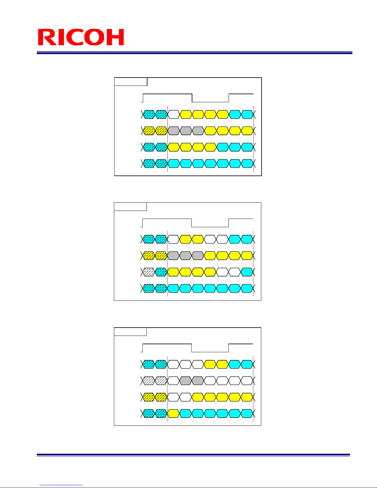
2.3 Data Order on the Camera Link Output
DA0 to DA11: 12bit data for one pixel from the first tap
DB0 to DB11: 12bit data for one pixel from the second tap
DA0 to DA9: 10bit data for one pixel from the first tap
DB0 to DB9: 10bit data for one pixel from the second tap
DA0 to DA7: 8bit data for one pixel from the first tap
DB0 to DB7: 8bit data for one pixel from the second tap
DA8 DA5 DA4 DA3 DA2 DA1 DA0
DA9DA10DA11DB8
DB10DB11
DB9DB0DB1
DB2DB3DB4DB5LVALFVALDVAL
SP DA6DA7DB6DB7
X0
X1
X2
X3
XCLK
DA1 DA0
DA9DA10
DB2DB3
DA6DA7
2TAP12bit
DA8 DA5 DA4 DA3 DA2 DA1 DA0
DA9DB8DB9DB0DB1 DB8DB9
DB2DB3DB4DB5LVALFVALDVAL
SP DA6DA7DB6DB7
X0
X1
X2
X3
XCLK
DA1 DA0
DA9
DB2DB3
DA6DA7
2TAP10bit
NC NC
NC NC
NC
DA5 DA4 DA3 DA2 DA1 DA0DB0
DB1DB2DB3DB4DB5
LVALFVALDVAL
SP DA6DA7DB6DB7
X0
X1
X2
X3
XCLK
DA1 DA0
DB1DB2
DA6DA7
2TAP8bit
NC
NC
NC NC
NC NC NC
NC
NCNC

14/31
FV-L500B1
User’s Guide Rev. 1.02
2.4 2 aps ransferring Image (2XE-1Y)
X
W
Y
H
X
W-1
Y
H
X
2
Y
H
X
1
Y
H
ap1
Sep X = 1
Sep Y = 1
X
1
Y
H-1
X
2
Y
H-1
X
W
Y
H-1
X
W-1
Y
H-1
X
1
Y
1
X
1
Y
2
X
2
Y
1
X
2
Y
2
X
W-1
Y
2
X
W
Y
2
X
W-1
Y
1
X
W
Y
1
ap2
X
W/2
Y
1
X
W/2
Y
2
X
W/2
Y
H-1
X
W/2
Y
H
X
W/2+1
Y
H
X
W/2+1
Y
H-1
X
W/2+1
Y
2
X
W/2+1
Y
1
Sep X = 1
2.5 Pixel ransferring Image
Pixeln of DataA: nth pixel being transferred from the AP1
Pixeln of DataB: nth pixel being transferred from the AP2
Pixel1 of
DataA
Pixel1 of
DataB
Pixel2 of
DataA
Pixel2 of
DataB

15/31
FV-L500B1
User’s Guide Rev. 1.02
Camera Operational Mode
3.1 Normal Mode
In this mode, the images are output continuously.
3.1.1 Frame Exposure
3.1.2 Electric Shutter
Exposur e t i me
I nt er nal VD
CCD
exposur e
Vi deo out
Ex p o s u r e
t i me
I nt er n a l VD
CCD
e x p o s u r e
Vi de o o u t

16/31
FV-L500B1
User’s Guide Rev. 1.02
3.2 Pulse Width rigger Mode
In this “pulse width trigger mode” with positive polarity, the camera exposure starts at the rising edge of the
trigger signal and stops at the falling edge of the trigger signal. herefore, in the case that the exposure positive
polarity is selected, the actual exposure occurs when the trigger signal is at high state.
3.2.1 Pulse Width rigger Mode(V-Reset)
Note 1: he camera does NO switch to normal mode when the long exposure mode is selected.
his timing chart shows when the long exposure mode selected.
Note 2: he internal VD signal is reset immediately after the exposure is finished as depicted, and the video output
original is sent out according to that reset VD timing.
Note 3: he exposure time is controlled by the pulse width of the trigger signal as depicted.
Exposure
time
Max. 1H
Sweep charges
Automatically switch to the normal
mode if the pulse width of the
trigger signal is more than
500 mseconds.
*Note. 1
Camera mode
Internal VD
CCD exposure
rigger signal
(Positive)
Video out
*Note. 2
*Note. 3
FVAL
Normal mode rigger mode Normal mode

17/31
FV-L500B1
User’s Guide Rev. 1.02
3.2.2 Pulse Width rigger Mode (Non-Reset)
Note 1: he camera does NO switch to normal mode when the long exposure mode is selected.
his timing chart shows with the long exposure mode selected.
Note 2: he internal VD signal does not reset by the trigger signal.
he video output signal is sent out at the next internal VD timing.
Note 3: he exposure time is controlled by the pulse width of the trigger signal as depicted.
Note 4: he FVAL signal does not output when the exposure by the trigger signal does not exists.
3.2.3 Exposure iming
Notes: he trigger signal equal to or shorter than 30 CLK is removed by the filtering system.
Input trigger signal has to be more than 31 CLK pulse width.
he exposure starts 198 CLK after the rising edge of the trigger signal.
Exposure
time
Sweep charges
Automatically switch to the normal
mode if the pulse width of the
trigger signal is more than
500 mseconds.
*Note. 1
Camera mode
Internal VD
CCD exposure
rigger signal
(Positive)
Video out
*Note. 3
FVAL
*Note. 4
Next VD
*Note. 2
Next VD
Normal mode Normal moderigger mode
1'
SUB
SG
(741 CLK)
rigger signal
Exposure time
Exposure time: 1' = 1 + 741 CLK
1
30 CLK
Filtering *Note.1

18/31
FV-L500B1
User’s Guide Rev. 1.02
3.3 Edge Preset rigger Mode
In this “edge preset trigger mode”, the camera exposure starts at the rising edge of the trigger signal like the
“pulse width trigger mode” in the previous sections. However, in this mode, the exposure duration time is based on the
preset value stored by the by the camera setting communication.
3.3.1 Edge Preset rigger Mode (V-Reset)
Note 1: he camera does NO switch to the normal mode when the long exposure mode is selected.
his timing chart shows when the long exposure mode is selected.
Note 2: he internal VD signal is reset immediately after the exposure is finished as depicted and the video output
signal is sent out according to the reset VD timing.
Note 3: he exposure time is preset by the camera setting communication as “shutter speed”.
Exposure
time
Max. 1H
Automatically switch to the normal
mode if the pulse width of the
trigger signal is more than
500 mseconds.
*Note. 1
Camera mode
Internal VD
CCD exposure
rigger signal
(Rising edge)
Video out
*Note. 2
*Note. 3
FVAL
Normal mode Normal moderigger mode
19/31
FV-L500B1
User’s Guide Rev. 1.02
3.3.2 Edge Preset rigger Mode (Non-Reset)
Note 1: he camera does NO switch to normal mode when the long exposure mode is selected.
his timing chart shows when the long exposure mode selected.
Note 2: he internal VD signal does not reset by the trigger signal.
he video output signal is sent out at the next internal VD timing.
Note 3: he exposure time is preset by the camera setting communication as “shutter speed”.
Note 4: he FVAL signal does not output when the exposure by the trigger signal does not exists.
3.3.3 Exposure iming
Notes: he trigger signal equal to or shorter than 30 CLK is removed by the filtering system.
Input trigger signal has to be more than 31 CLK pulse width.
he exposure starts198 CLK after the rising edge of the trigger signal.
Exposure
time
Automatically switch to the normal
mode if the pulse width of the
trigger signal is more than
500 mseconds.
*Note. 1
Camera mode
Internal VD
CCD exposure
rigger signal
(Rising edge)
Video out
*Note. 3
FVAL
*Note. 4
Next VD
*Note. 2
Next VD Next VD
Normal mode rigger mode Normal mode
rigger signal
Exposure time
1'
SUB
SG
Exposure time: 1' = Preset electronic shutter
Filtering *Note.1
30CLK
20/31
FV-L500B1
User’s Guide Rev. 1.02
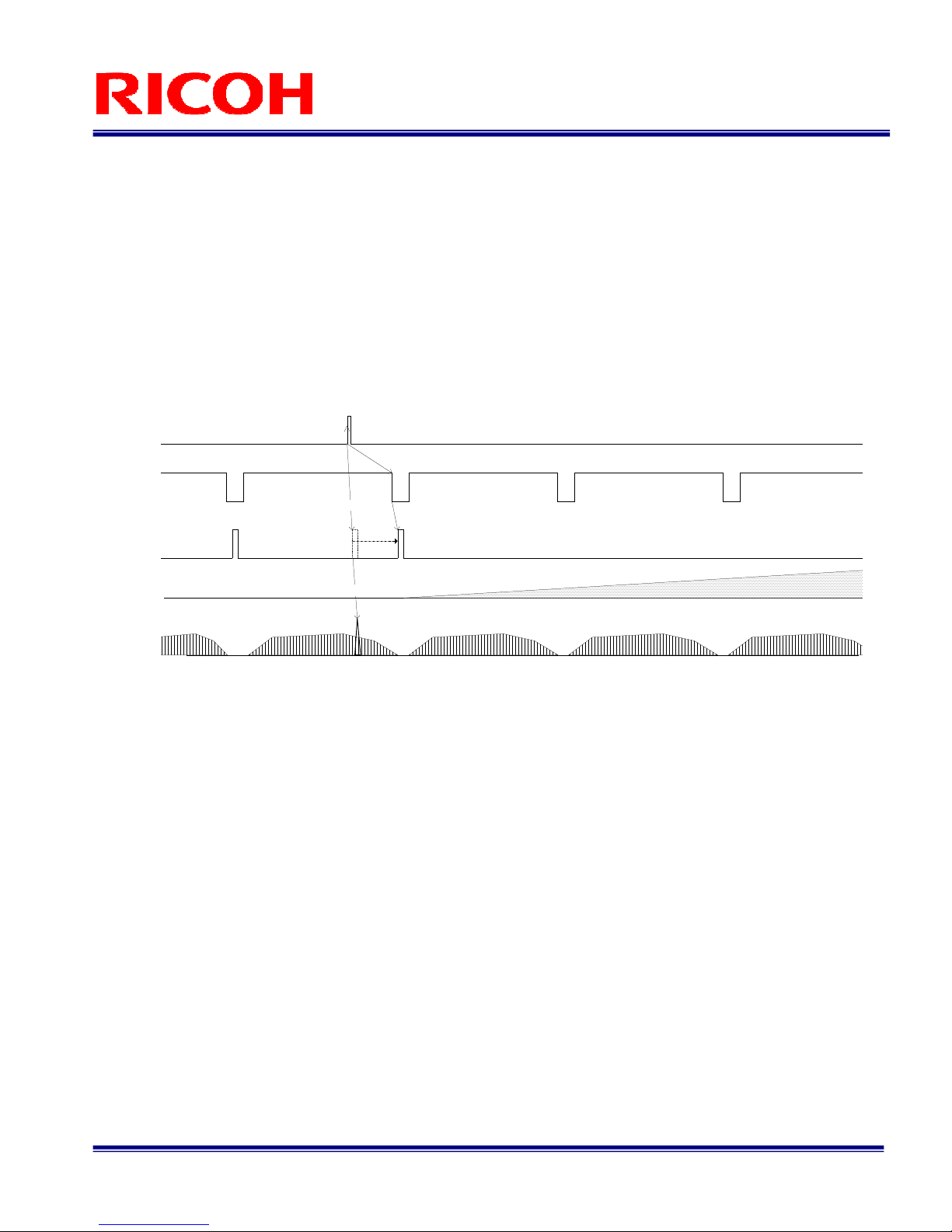
3.4 H Reset Mode
Normally, video noise appears when the beginning of trigger signal is applied before finishing the video read-out
of the previous frame. his noise is caused by the SUB pulse, which is activated to clear all residual charges on the
CCD prior to a new exposure. By selecting this “H. Reset Mode”, the camera automatically holds the actual activation of
trigger until the next horizontal blanking period. By doing this, the SUB pulse is activated during the horizontal blanking
period and the noise in image can be avoided.
Due to the principal of this operation, there can be maximum “1 H” of delay of actual trigger signal.
Next HD
Video out
SUB pulse
Internal HD
CCD exposure
rigger signal
(Rising edge)
Noise
NoiseNoise
Noise
Normal SUB pulse timing
Other manuals for FV-L500B1
1
Other Ricoh Security Camera manuals


Popular Security Camera manuals by other brands

Tiandy
Tiandy TY-CG6E-30WSL Operator's manual

Vivotek
Vivotek SD7151 Quick installation guide

Optiview
Optiview VR Series Wireless IP C-Mount Camera WIPCAM Specification sheet

Digital Watchdog
Digital Watchdog MEGAPIX DWC-MV94Wi36T quick start guide

Genie
Genie WIPX2LBVLPR user manual

Burg Wächter
Burg Wächter SNC-241CPRBIA Quick installation guide

Direct IP
Direct IP Idis DC-S6286HRXL-A Operation manual

Vitek
Vitek VT-SMKC1 - DATASHEET 2 datasheet

Swann
Swann Slimline SWIFI-SLMFLCW quick start guide

Direct IP
Direct IP IDIS DC-S6281FX quick guide

StarDot Technologies
StarDot Technologies NetCam SC user manual

Comtech EF Data
Comtech EF Data CT-C4002DM user manual


