Ridder RLD200 User manual

Product Manual
Ridder LogicDrive RLD200
265110EN - 2017.07 - V03
Ridder Drive Systems
Lorentzstraat 36-38 3846 AX Harderwijk
P.O. Box 360 3840 AJ Harderwijk
The Netherlands
T+31 (0)341 416 854 F+31 (0)341 416 611
Iwww.ridder.com Einfo@ridder.com

Ridder Drive Systems T+31 (0)341 416 854 F+31 (0)341 416 611 I www.ridder.com
2
This product manual contains important informaon for installers on how to connect and
commission a Ridder LogicDrive RLD200. All acvies in this respect should be carried out by
qualied and skilled mechanical and / or electrical installers in proper and safe condions.
Table of contents
1.1 LogicDrive RLD200 product manual
1.1 LogicDrive RLD200 product manual ............................................. 2
2.1 LogicDrive RLD200 descripon .................................................3
2.2 LogicDrive RLD200 applicaon .................................................3
2.3 LogicDrive RLD200 technical specicaons .......................................4
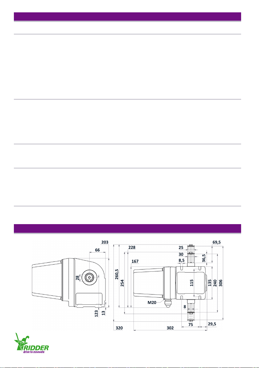
2.4 LogicDrive RLD200 dimensions..................................................4
2.5 LogicDrive RLD200 winch belt pull force for venlaon systems ...................... 5
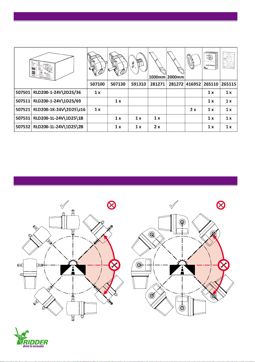
2.6 LogicDrive RLD200 packaging contents . . . . . . . . . . . . . . . . . . . . . . . . . . . . . . . . . . . . . . . . . . 6
3.1 LogicDrive RLD200 mounng posions .......................................... 6
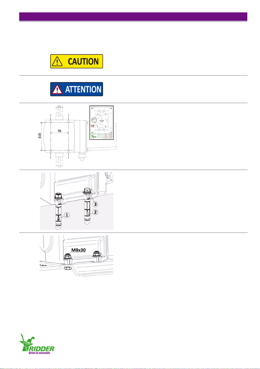
3.2 Mounng the LogicDrive RLD200 ...............................................7
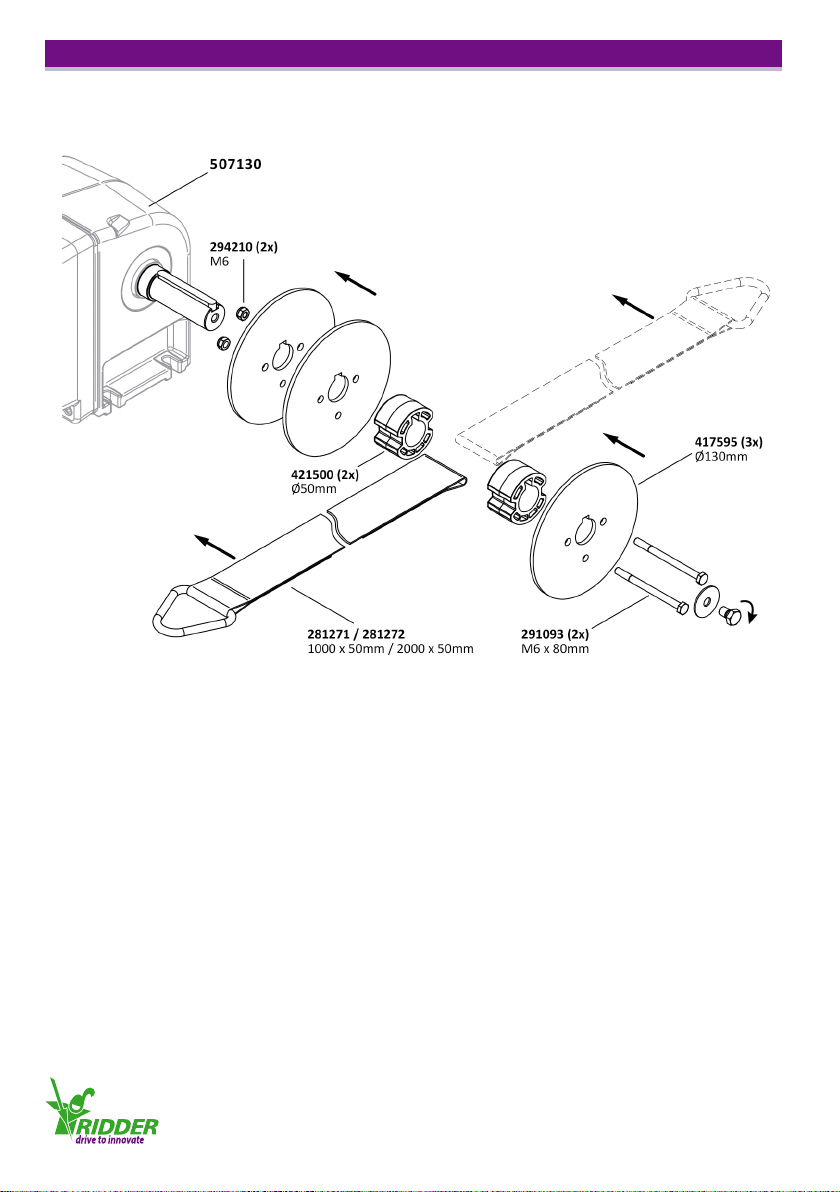
3.3 Mounng the belt drum and winch belt .........................................8
3.4 Pre-winding the winch belt onto the belt drum ....................................9
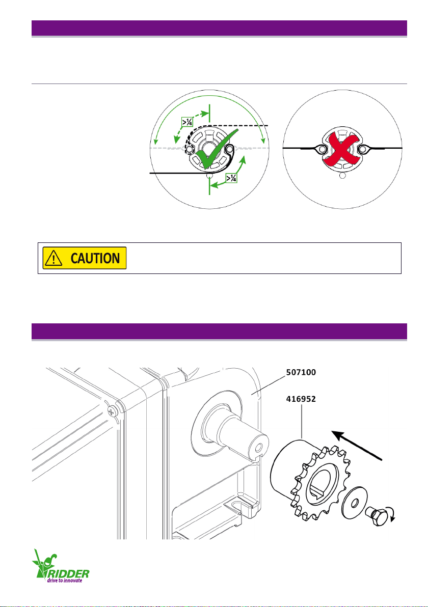
3.5 Mounng the sprocket ........................................................9
4.1 Connecon and operaon - abbreviaons ....................................... 10
4.2 Connecng the control components and switch materials, and cable lengths .......... 10
4.3 LogicDrive RLD200 wiring diagram and operang elements ........................11
4.4 LogicDrive RLD200 rotaonal direcon, and end and emergency posions ............12
5.1 Condions and criteria for teaching in the LogicDrive RLD200 . . . . . . . . . . . . . . . . . . . . . . . 13
5.2 Operang the LogicDrive RLD200 . . . . . . . . . . . . . . . . . . . . . . . . . . . . . . . . . . . . . . . . . . . . . . 13
5.3 LogicDrive RLD200 status LEDs ................................................15
5.4 Control signal of climate controller and emergency posion ........................15
6.1 Teaching in the LogicDrive RLD200 - Programming the end posions .................16
6.2 Teaching in the LogicDrive RLD200 - Programming an emergency posion ............18
6.3 Teaching in the LogicDrive RLD200 - Erasing an end posion ........................19
6.4 Teaching in the LogicDrive RLD200 - Erasing the emergency posion .................20
7.1 LogicDrive RLD200 alarm contact .............................................. 21
8.1 LogicDrive RLD200 blink codes of status LEDs .................................... 21
9.1 LogicDrive RLD200 maintenance ...............................................24
10.1 LogicDrive RLD200 troubleshoong ............................................24
10.2 Technical Support ...........................................................25
10.3 Environment ...............................................................25
11.1 LogicDrive RLD200 accessories ................................................ 26
12.1 Meaning of warnings in this product manual ..................................... 27

Ridder Drive Systems T+31 (0)341 416 854 F+31 (0)341 416 611 I www.ridder.com
3
The LogicDrive RLD200 is a maintenance-free drive unit for
accurately and awlessly opening and closing air inlet aps,
air valves and venlaon curtains in livestock houses.
The RLD200 features a sleek housing with a high protecon
class of IP65. This not only makes the RLD200 resistant
to water and dust, but also easy to clean.
The RLD200 is equipped with a self-locking worm wheel
transmission which ensures that the drive sha is braked when the drive unit stops moving. The
matching gear and worm wheel transmissions mean the drive unit runs very quietly. The RLD200
is available with a one-sided or two-sided drive sha for mounng one or more belt drums or
sprockets. The RLD200 is durable and has virtually no duty cycle restricon.
The RLD200 features a 24 V DC stepper motor with intelligent motor control. Using a 0-10 V control
signal, the RLD200 can be posioned extremely accurately. The revoluon range of the RLD200 drive
unit is electronically adjustable from 0.25 to 100 revoluons of the drive sha. The integrated motor
control unit of the RLD200 protects the drive unit against overloading and adjusts it to a taught-in
posion in the event that the control signal is lost (requires emergency power supply). The RLD200
is equipped with a contact to transmit alarm signals.
The RLD200 drive unit can be controlled and powered by the Ridder
LogicControl RLC100 control units (or equivalent) and Ridder
LogicPower RLP200 emergency power supply (or equivalent).
This allows the RLD200 to be adjusted to an emergency posion
should a power failure occur.
The standard RLD200 is nished with a graphite grey powder coang.
The LogicDrive RLD200 drive units are designed to adjust the posions of air inlet aps, air valves
and venlaon curtains in livestock houses and crop storage buildings.
Other applicaons require permission by Ridder Drive Systems.
In addion, the following condions apply when using the LogicDrive RLD200:
● The construcon of the RLD200 may not be modied or changed.
● The applicable regulaons and guidelines (e.g. CE) must be observed.
● The RLD200 may not be used to li or move people.
2.2 LogicDrive RLD200 applicaon
2.1 LogicDrive RLD200 descripon

Ridder Drive Systems T+31 (0)341 416 854 F+31 (0)341 416 611 I www.ridder.com
4
2.4 LogicDrive RLD200 dimensions
2.3 Technical specicaons LogicDrive RLD200
Mechanical
Torque 200 Nm
Speed 1 rpm
Winch belt speed 15-22 cm/min
Winch belt length 1 m | 2 m
Rotaonal range between end posions 0,25-100 rev
Drive unit Self-locking
Dimensions (WxHxD) 110 mm x 150 mm x 230 mm
Weight 20 - 23 kg
Electrical
Supply voltage 24 V DC (± 10 %)
Maximum current 4 A
Power 96 W
Alarm contact 24 V AC/DC, 1 A
Protecon Mechanical and thermal overload
Control
Control signal 0-10 V DC / 10-0 V DC
Control signal dierence (A - B) > 2 V DC
Emergency posion control
Lower value of control signal > 1 V DC
Acvaon signal < Lower value of control signal x 0.5 V DC
Emergency posion (C) Freely adjustable
between or to one of the end posions (A, B)
Environment
Protecon class IP65
Ambient temperature 0-40 °C (32-104 °F)

Ridder Drive Systems T+31 (0)341 416 854 F+31 (0)341 416 611 I www.ridder.com
5
2.5 LogicDrive RLD200 winch belt pull force for venlaon systems
Winch belt forces depend on:
● Type of LogicDrive RLD200 (one-or two-sided output drive sha, single or double winch strap).
● The required winding length of the winch belt.
Winding length limitaons:
● Pre-winding the winch belt around the drum (± 100 mm, see also §3.4).
● Winding capacity of drum (± 2000 mm).
Graph lines:
1. RLD200 winch belt pull force per winch belt: One winch drum with a single wing belt
(graph line ①).
2. RLD200 winch belt pull force per winch belt: One winch drum winch with a double winch belt
(graph line ②).
Belt forces only applicable for opening and closing air inlets and
valves! Forces not allowed for liing or hoisng objects or people!

Ridder Drive Systems T+31 (0)341 416 854 F+31 (0)341 416 611 I www.ridder.com
6
Please observe the following mounng posions when installing the LogicDrive RLD200.
3.1 LogicDrive RLD200 mounng posions
2.6 LogicDrive RLD200 packaging contents
Each LogicDrive RLD200 unit is packaged in a box together with its accessories. The following table
shows which items are supplied in each box.
315° < α < 45° 45° ≤ α ≤ 315°
45°
315°
90°
270°
180°
α=0°
315° < α < 45° 45° ≤ α ≤ 315°
45°
315°
90°
270°
180°
α=0°

Ridder Drive Systems T+31 (0)341 416 854 F+31 (0)341 416 611 I www.ridder.com
7
3.2 Mounng the LogicDrive RLD200
1
Please ensure that the RLD200 is mounted securely, so
that the building structure can suciently absorb the
forces applied.
2
When mounng the RLD200, ensure that the motor
cover remains accessible so you will have no problems
connecng and teaching in the RLD200.
3
To drill the mounng holes, a drilling template has been
included. Use the drilling template to mark the holes onto
the wall or structure.
If you do not wish to use the template, mark the holes as
shown opposite.
4a
Mounng the unit to a wall (blind holes).
● Drill holes for wedge bolts or sleeves.
● Secure the unit using the following fasteners:
① M8 x 75 wedge bolt (with washer, spring washer
and nut).
② M8 wedge sleeve (with ③).
③ M8 x 65 hexagon bolt (with washer and spring
washer).
4b
Mounng the unit to a steel structure (through holes).
● Drill ø 8.5 mm holes.
● M8 x 30 hexagon screw (4x).
● M8 self-locking nut M8 (4x).
● M8 body washer (8x).
Mount the LogicDrive RLD200 according to the following instrucons and in a mounng posion as
described in §3.1.

Ridder Drive Systems T+31 (0)341 416 854 F+31 (0)341 416 611 I www.ridder.com
8
Mount the belt drum and winch belt (or belts) for the RLD200 as follows:
3.3 Mounng the belt drum and winch belt

Ridder Drive Systems T+31 (0)341 416 854 F+31 (0)341 416 611 I www.ridder.com
9
3.4 Pre-winding the winch belt onto the belt drum
To safely use the belt drum and winch belt of the LogicDrive RLD200, it is necessary to rst pre-wind
the belt onto the drum:
Not pre-winding the winch belt may result
in injury at high belt or drum loads.
3.5 Mounng the sprocket
Mount the sprocket for the RLD200 as follows:
Belt drum
with a single belt:
●At least ¼ revoluon.
Belt drum
with a double belt:
●At least ¼ revoluon.

Ridder Drive Systems T+31 (0)341 416 854 F+31 (0)341 416 611 I www.ridder.com
10
4.1 Connecon and operaon - abbreviaons
The data in the table below allows you to determine the required conductor diameter, based on the
cable length and supply voltage.
4.2 Connecng the control components and switch materials, and cable lengths
Symbol Descripon
RLD200
AIN 0-10 V DC Control signal
C Emergency Posion
DIR A | DIR B Push buon for rotaonal direcon A | B
GND Ground (earth) terminal
LED A | LED B LED for rotaonal direcon A | B (Green, control board X1)
PROG Programming buon
RELAY Alarm contact terminal (control board X1)
RUN LED Status LED for motor board X2 (green)
S1 DIP Switch (control board X1)
X1 | X2 Control board | Motor board
M1 - RLC100
1 - Sgn 0-10 V DC control signal from climate controller
2 - Gnd Return wire of control signal from climate controller
3 - Scr Shield of control cable
4 - AL Alarm signal from LogicDrive
5 - AL Return wire of alarm signal from LogicDrive
6 - Sgn 0-10 V DC control signal to LogicDrive
7 - Gnd Return wire of control signal to LogicDrive
8 - Scr Shield of alarm and control signal cables
9 - 24 V 24 V DC LogicDrive power supply
10 - Gnd Return wire of LogicDrive power supply
Please use only suitable control components and switch materials.
Make sure you are using the correct equipment by consulng the
informaon of the control components and switch materials.
The LogicDrive requires a supply voltage of 24 VDC ± 10 %.
Cable Voltage Min. conductor diameter Max. cable length at 24 V DC
Power cable 24 VDC 1.5 mm² 30 m
2.5 mm² 50 m
Control cable 0-10 VDC 0.75 mm²
Note: If longer cable lengths are required, you can consider compensang for the voltage loss by
increasing the supply voltage of the LogicDrive RLD200. A conductor diameter of 1.5 mm² requires a
1 V DC increase per 10m of cable length and a diameter of 2.5 mm² requires a 1 V DC increase per
15 m of cable length (both in addion to the relevant value specied in the table).

Ridder Drive Systems T+31 (0)341 416 854 F+31 (0)341 416 611 I www.ridder.com
11
The diagram below shows how to wire the LogicDrive RLD200. It also shows where the operang
elements are located on the control board X1 and the motor board X2.
4.3
LogicDrive RLD200 wiring diagram and operang elements
Always use separate cables for the 24 VDC supply voltage
and 0-10 VDC control signal.
Connect the shield in the control box and NOT in the RLD200!

Ridder Drive Systems T+31 (0)341 416 854 F+31 (0)341 416 611 I www.ridder.com
12
4.4 LogicDrive RLD200 rotaonal direcon, and the end and emergency posions
The gure below shows the control buons DIR A and DIR B along with the corresponding rotaonal
direcon of A and B. The gure also shows where the end and emergency posions are located
relave to each other.

Ridder Drive Systems T+31 (0)341 416 854 F+31 (0)341 416 611 I www.ridder.com
13
5.1 Condions and criteria for teaching in the LogicDrive RLD200
The following condions and criteria apply to teaching in the LogicDrive RLD200:
Control signal
Always use the 0-10 V control signal of the climate
controller to teach in the RLD200.
The voltage dierence of the control signal must be at
least 2 V to teach in the RLD200.
Teach-in sequence
You can teach in the RLD200 from end posion A to
end posion B and vice versa.
The 0-10 V control signal may increase from A to B or
from B to A.
Minimum
movement
The minimum movement between end posions A and
B is 90° (¼ revoluon) of the drive sha.
Emergency posion
To use the emergency posion C, the minimum control
voltage must be higher than 1 V.
The emergency posion C must be programmed
between or to one of the end posions A or B.
5.2 Operang the LogicDrive RLD200
Chapter 6 describes how to teach in the LogicDrive RLD200. This secon describes the control op-
ons for teaching in the RLD200.
Teach-in
mode
The DIP switch on the control board X1 allows
you to acvate the teach-in mode of the RLD200.
To do so, adjust the DIP switch in the direcon of
the control buons.
Operang
mode
The DIP switch on the control board X1 allows
you to acvate the operang mode of the
RLD200. To do so, adjust the DIP switch in the
direcon of the terminal strip.

Ridder Drive Systems T+31 (0)341 416 854 F+31 (0)341 416 611 I www.ridder.com
14
Hold to run
Operaon
DIR A
To operate the unit in rotaonal direcon A in
teach-in mode, press and hold down push buon
‘DIR A’. If end posion A has been programmed,
the RLD200 will stop at this posion.
Hold to run
Operaon
DIR B
To operate the unit in rotaonal direcon B in
teach-in mode, press and hold down push buon
‘DIR B’. If end posion B has been programmed,
the RLD200 will stop at this posion.
Pulse
Operaon
DIR A
To acvate pulse operaon for rotaonal
direcon A, rst press and hold down control
buon ‘DIR A’, then press the programming
buon ‘PROG’, and then release both buons.
Pulse operaon can be stopped at any me
by pressing one of the control buons. If end
posion A has been programmed, the RLD200
will stop at this posion.
Pulse
Operaon
DIR B
To acvate pulse operaon for rotaonal
direcon B, rst press and hold down control
buon ‘DIR B’, then press the programming
buon ‘PROG’, and then release both buons.
Pulse operaon can be stopped at any me
by pressing one of the control buons. If end
posion B has been programmed, the RLD200
will stop at this posion.
Stop pulse
operaon
Pulse operaon can be stopped at any me by
pressing one of the control buons.
When operang the LogicDrive RLD200, do not exceed
the limit posions to avoid damage or injury!

Ridder Drive Systems T+31 (0)341 416 854 F+31 (0)341 416 611 I www.ridder.com
15
5.3 LogicDrive RLD200 status LEDs
While the unit is in teach-in or operang mode, you can determine the status of
the RLD200 by the LEDs intended for this purpose. These status LEDs are located
on the control board X1 (LED A and B) and on the motor board X2 (RUN LED).
For more informaon on the locaons of the LEDs, see §4.3. The LED codes are
discussed from §6.1 onwards and their meanings are explained in §8.1.
5.4 Control signal of climate controller and emergency posion
The table below provides an overview of common control signals of climate controllers. Please note
that you must also correctly set up the control unit used (such as the Ridder LogicControl RLC101).
To do so, see the manual of the control unit.
To teach in the RLD200, the dierence in control signal output of the climate controller (i.e.
between the open and close commands) must be at least 2 V. A larger dierence is recommended
to control the RLD200 more accurately.
To teach in an emergency posion, the minimum value of the control signal must be 1 V. If the
control signal is lost, the RLD200 will move to the taught-in emergency posion. This does, however,
require the RLD200 to be powered by a 24 V DC supply voltage (from the mains or an emergency
power supply).
Control
signal Descripon
Emergency
posion
0-10 V
● The RLD200 is controlled by a 0-10 V control signal.
● The end posions correspond to 0 V and 10 V.
● The RLD200 does not detect the loss of the control signal.
Not possible
1-10 V
● The RLD200 is controlled by a 1-10 V control signal.
● The end posions correspond to 1 V and 10 V.
● The RLD200 detects the loss of the control signal.
Possible
2-10 V
● The RLD200 is controlled by a 2-10 V control signal.
● The end posions correspond to 2 V and 10 V.
● The RLD200 detects the loss of the control signal.
Possible
To control the RLD200, the dierence in control signal output (i.e.
between the open and close commands) must be at least 2 VDC.
To teach-in an emergency posion, the minimum value
of the control signal range must be greater than 1 VDC.

Ridder Drive Systems T+31 (0)341 416 854 F+31 (0)341 416 611 I www.ridder.com
16
The following condions apply to programming the end posions:
● No end posion/posions may have been programmed (to erase end posions, see §6.3).
● The RLD200 must be taught in with the control signal of the climate controller!
● The dierence in control signal output for both end posions must be at least 2 V.
6.1 Teaching in the LogicDrive RLD200 - Programming the end posions
uDescripon Picture
1
Set the DIP switch S1 to ‘Teach-in mode’.
2Set the control unit of the RLD200, such as the Ridder
LogicControl RLC101, to ‘Auto’ mode.
3
From the climate controller, send the desired control
signal (0-10 V DC) for the end posion A to be
programmed.
4
Use buon ‘DIR A’ to set the desired end posion A.
If necessary, use buon ‘DIR B’ to adjust end posion A.
Pulse operaon is also possible (see §5.2). If you use pulse
operaon, ensure that the end posion is not exceeded!
5
To save the selected end posion A, rst press and hold
down the programming buon ‘PROG’ (①) and then
press the control buon ‘DIR A’ (②). Release both
buons once the corresponding ‘LED A’ starts blinking
slower (③).

Ridder Drive Systems T+31 (0)341 416 854 F+31 (0)341 416 611 I www.ridder.com
17
6
From the climate controller, send the desired control
signal (0-10 V DC) for the end posion B to be
programmed.
7Use buon ‘DIR B’ to set the desired end posion B.
If necessary, use buon ‘DIR A’ to adjust end posion B.
8
To save the selected end posion B, rst press and hold
down the programming buon ‘PROG’ (①) and then
press the control buon ‘DIR B’ (②). Release both
buons once the corresponding ‘LED B’ starts blinking
slower (③).
9
Set the DIP switch S1 to ‘Operang mode’.
10 End posions A and B have now been programmed.

Ridder Drive Systems T+31 (0)341 416 854 F+31 (0)341 416 611 I www.ridder.com
18
The following condions apply to programming an emergency posion:
● End posions A and B must have been programmed (see §6.1).
● The minimum value of the control signal must be greater than 1 V DC.
6.2 Teaching in the LogicDrive RLD200 - Programming an emergency posion
uDescripon Picture
1Set DIP switch S1 to ‘Teach-in mode’.
2
Use buon ‘DIR A’ or ‘DIR B’ to set the desired emergency
posion C.
Pulse operaon is also possible (see §5.2).
3
To save the emergency posion C, press the programming
buon ‘PROG’ (①). Release the buon once both LEDs
(i.e. ‘LED A’ and ‘LED B’) start blinking alternately in quick
succession (②).
4
Set the DIP switch S1 to ‘Operang mode’.
5The emergency posion has now been programmed.

Ridder Drive Systems T+31 (0)341 416 854 F+31 (0)341 416 611 I www.ridder.com
19
The following condions apply to erasing an end posion:
● The end posion to be erased (A or B) must have been programmed (see §6.1).
6.3 Teaching in the LogicDrive RLD200 - Erasing an end posion
uDescripon Picture
1
Set DIP switch S1 to ‘Teach-in mode’.
Depending on the situaon, ‘LED A’ and ‘LED B’ will blink
according to a certain blink code (see §8.1).
2-A
To erase end posion A, rst press and hold down the
programming buon ‘PROG’ (①) and then press the
control buon ‘DIR A’ (②). Release both buons once
the corresponding ‘LED A’ starts blinking faster (③).
Remarks:
● End posion A can be erased while in any posion!
● The blink code for ‘LED B’ may be dierent.
2-B
To erase end posion B, rst press and hold down the
programming buon ‘PROG’ (①) and then press the
control buon ‘DIR B’ (②). Release both buons once
the corresponding ‘LED B’ starts blinking faster (③).
Remarks:
● End posion B can be erased while in any posion!
● The blink code for ‘LED A’ may be dierent.
3The end posion/posions and the taught-in emergency posion have now been erased.
Re-program the end posion/posions and the emergency posion (see §6.1 and §6.2).
If an emergency posion has been programmed,
it will also be cleared when an end posion is erased!

Ridder Drive Systems T+31 (0)341 416 854 F+31 (0)341 416 611 I www.ridder.com
20
The following condions apply to erasing an emergency posion:
● Emergency posion C must have been programmed (see §6.2).
6.4 Teaching in the LogicDrive RLD200 - Erasing an emergency posion
uDescripon Picture
1
Set the DIP switch S1 to ‘Teach-in mode’.
Depending on the situaon, ‘LED A’ and ‘LED B’ will blink
according to a certain blink code (see §8.1).
2
To erase emergency posion C, press the programming
buon ‘PROG’ (①). Release the buon once both LEDs
(i.e. ‘LED A’ and ‘LED B’) turn o briey, one aer the
other (②).
Remarks:
● Emergency posion C can be erased while in any
posion!
3
The emergency posion has now been erased.
If desired, re-program the emergency posion (see §6.2, from point 2). If you do not wish to
program a new emergency posion, proceed with step 4.
4
Set the DIP switch S1 to ‘Operang mode’.
5The emergency posion has now been erased.
This manual suits for next models
10
Table of contents
Other Ridder DC Drive manuals
Popular DC Drive manuals by other brands

WEG
WEG CFW900 user manual

SIEB & MEYER
SIEB & MEYER SD2 Hardware description

Trane
Trane TR200 Series Preventive Maintenance Instructions

Danfoss
Danfoss VLT AQUA Drive FC 202 Design guide

SEW-Eurodrive
SEW-Eurodrive MOVIMOT MM D Series Compact operating instructions

TOPTEK
TOPTEK TOPVERT E1 Series quick start